Temperature-Dependent High-Speed Dynamics
of Terahertz Quantum Cascade Lasers
Gary Agnew, Member, IEEE, Andrew Grier, Thomas Taimre, Associate Member, IEEE,
Karl Bertling, Member, IEEE, Yah Leng Lim, Member, IEEE, Zoran Ikoni´c, Paul Dean, Alexander Valavanis,
Paul Harrison, Dragan Indjin, and Aleksandar D. Raki´c, Senior Member, IEEE
Abstract—Terahertz frequency quantum cascade lasers offer a potentially vast number of new applications. To better under-stand and apply these lasers, a device-specific modeling method was developed that realistically predicts optical output power un-der changing current drive and chip temperature. Model param-eters are deduced from the self-consistent solution of a full set of rate equations, obtained from energy-balance Schr¨odinger– Poisson scattering transport calculations. The model is, thus, derived from first principles, based on the device structure, and is, therefore, not a generic or phenomenological model that merely imitates the expected device behavior. By fitting polynomials to data arrays representing the rate equation parameters, we are able to significantly condense the model, improving memory usage and computational efficiency.
Index Terms—Quantum cascade laser, rate equation model, electro-optical dynamics, thermal roll-over, bandwidth, turn-on behavior, free space communication.
I. INTRODUCTION
T
HE terahertz (THz) band of frequencies [1] has become increasingly accessible in recent years via emerging tech-nologies for generating and detecting THz radiation. Amongst the many potential applications are broadband short-range com-munication [2]–[6], heterodyne detection of exogenous THz ra-diation, imaging, and material analysis [7]. The THz quantumManuscript received October 1, 2016; revised December 5, 2016; accepted December 8, 2016. This work was supported under the Australian Research Council’s Discovery Projects funding scheme (DP 160 103910) and the Queens-land Government’s Advance QueensQueens-land programme. This work was also sup-ported by the Engineering and Physical Sciences Research Council, U.K., under Grants EP/J017671/1 and EP/J002356/1 and DTG award, by the Royal Society under Wolfson Research Merit Awards WM110032 and WM150029, and by the European Cooperation in Science and Technology (Action BM1205).
G. Agnew, K. Bertling, Y. L. Lim, and A. D. Raki´c are with the School of Information Technology and Electrical Engineering, The University of Queens-land, Brisbane, QLD 4072, Australia (e-mail: [email protected]; [email protected]; [email protected]; [email protected]).
A. Grier was with the School of Electronic and Electrical Engineering, Uni-versity of Leeds, Leeds LS2 9JT, U.K. He is now with Seagate Technology, Dublin, Ireland (e-mail: [email protected]).
T. Taimre is with the School of Mathematics and Physics, The University of Queensland, Brisbane, QLD 4072, Australia (e-mail: [email protected]).
Z. Ikoni´c, P. Dean, A. Valavanis, and D. Indjin are with the School of Elec-tronic and Electrical Engineering, University of Leeds, Leeds LS2 9JT, U.K (e-mail: [email protected]; [email protected]; [email protected]; [email protected]).
P. Harrison is with the Materials and Engineering Research Institute, Sheffield Hallam University, Sheffield S1 1WB, U.K (e-mail: [email protected]).
Color versions of one or more of the figures in this paper are available online at http://ieeexplore.ieee.org.
Digital Object Identifier 10.1109/JSTQE.2016.2638539
cascade laser, first demonstrated in 2002 [8], is a compact yet powerful semiconductor source of coherent THz radiation. Cur-rent devices are able to operate at temperatures as high as 129 K in continuous wave (cw) [9] and 200 K in pulsed mode [10], and emitting peak pulsed optical powers of greater than 1 W [11].
Modeling the dynamic behavior of THz QCLs is vital for understanding the more complex behaviors of these devices and thus for the development of new applications—more so, con-sidering that laboratory investigation of such behavior can be prohibitively expensive and experimentally challenging due to the extraordinarily short timescales on which some phenomena occur. Further, a growing class of THz QCL applications relies on the self-mixing effect [12]–[14], in which emissions from the device are reflected from a target back into the laser cavity, yield-ing information about the target [15]. Such retro-injected light (optical feedback) alters the device state and behavior, introduc-ing a new dimension of complexity into device behavior [16]. In these applications, a realistic model is an indispensable research tool. It may be necessary to consider the effects of optical feed-back even where it is undesirable, as failure to do so can lead to unexpected outcomes in behavior [17], [18].
The exemplar laser modeled in this paper is a bound-to-continuum (BTC) type QCL, a device that is particularly chal-lenging to model and optimize due to the relatively large number of quantum-confined subbands in the active region (AR). Full rate equation (RE) models can be solved in order to extract dy-namical information relating to all the intersubband transitions. Since the intersubband scattering processes are both temperature and electric field strength (voltage) dependent, it is necessary to determine these dependencies via first principles in order to properly model a device. However, full RE modeling is compu-tationally intensive and therefore restricted to static solutions. Moreover, solving full REs self-consistently with optical and thermal models is computationally challenging.
Reduced rate equations (RREs), which employ a subset of pa-rameters derived from the full RE model, offer a simple and prac-tical means of predicting a device’s dynamic behavior without the need to repeatedly solve the full set of REs self-consistently. In principle, slight changes in a QCL’s electric field distribution due to dynamical behavior necessitate re-calculation of the full self-consistent RE solution. In practice, ignoring the effect of these slight changes in electric field distribution on RRE pa-rameters leads to a second-order error in the RRE solution that is commonly considered insignificant. This makes it possible
to use RREs for both dynamic and static modeling [19], and self-consistent computation of the emitted THz optical power.
However, a commonly made assumption in the use of the three-level RRE model for QCLs is that RRE parameters have constant values. All the RRE parameters are in fact both temperature- and voltage-dependent. Simulation results based on the assumption are therefore valid only over the narrow range of voltages and temperatures for which the RRE parameters were calculated.
Various approaches have been taken in dealing with this problem [19]–[22], usually by addressing either temperature-dependent or voltage-temperature-dependent device behavior in isolation. Our modeling approach, introduced in [23], overcomes this difficulty by accommodating the temperature- and voltage-dependence of all RRE parameters over the full operating range of the device. With the addition of an AR temperature model to our rate equations, we are able to predict lattice temperature under changing excitation and cold finger temperature, thereby accounting for the temperature-dependence of the RRE param-eters. The resulting model is able to correctly reproduce the ex-perimentally observed variations in emitted optical power, from the temperature-dependent threshold current, through roll-over to cut-off.
The aim of this paper is to both present our study of the dy-namic turn-on behavior of a BTC THz QCL, and to provide a condensed version of our model to enable further investiga-tion. In the following sections we define the model (Section II), setting out the complete generic model and providing device-specific data for a real (exemplar) QCL; discuss the results (Section III) of exemplar model applications to (A) static con-ditions, to simulate and explore its light–current (LI) charac-teristics and (B) turn-on behavior to characterize its high speed dynamics; and offer our concluding remarks.
II. MODELDEFINITION
A. Exemplar QCL
The QCL we chose to model is a single mode GaAs/AlGaAs BTC 2.59 THz device that has been processed into a surface-plasmon Fabry-P´erot ridge waveguide and operates up to temperatures of 50 K in cw. This device has been previously characterized and used in a variety of applications including material analysis [15], [24] and imaging [25]. The band struc-ture is shown in Fig. 1, with the radiative transition’s states labeled ULL and LLL. A complete specification of the active re-gion heterostructure [26] is required to calculate device-specific RRE parameters from first principles.
B. Rate Equation Model
Our set of RREs reads:
dS(t) dt = −
1 τp S(t) +
βsp
τsp(T, V)N3(t) + MG(T, V)(N3(t)−N2(t))
[image:2.594.334.524.68.190.2]1 +εS(t) S(t) (1)
Fig. 1. Band diagram of our exemplar 2.59 THz BTC QCL. The radiative inter-subband transition is ULL→LLL (color online).
dN3(t)
dt = −G(T, V)
(N3(t)−N2(t))
1 +εS(t) S(t)
− 1
τ3(T, V)N3(t) +
η3(T, V)
q I(t) (2) dN2(t)
dt = +G(T, V)
(N3(t)−N2(t))
1 +εS(t) S(t)
+ τ 1
32(T, V)N3(t) +
η2(T, V)
q I(t)
− τ 1
21(T, V)N2(t) (3)
dT(t) dt =
1 mcp
I(t)V(T(t), I(t))−(T(tRth)−T0)
(4)
The symbolS(t)represents photon population,τp the pho-ton lifetime in the cavity,N3(t)the ULL carrier number,N2(t) the LLL carrier number,I(t)the current forcing function,qthe electronic charge,βsp the spontaneous emission factor,τsp the spontaneous emission lifetime (or radiative spontaneous relax-ation time), andM is the number of periods in the structure, 90 in the case of our exemplar QCL. Theη3 term in Eq. (2) mod-els carrier injection efficiency into the ULL and theη2 term in Eq. (3) models carrier injection efficiency directly into the LLL. The carrier lifetime for non-radiative transitions from the ULL to LLL isτ32, the total lifetime due to non-radiative transitions for the ULL carrier population isτ3, and the lifetime for tran-sitions from the LLL to the continuum isτ21. The gain factor is represented byG, as defined in [19]. We make provision for gain compression by including the term inεin Eqs. (1)–(3).
Parameters that depend on temperature (T) and voltage (V) are expressed as functions ofVandT,(V, T)in the RREs. These include the gain factorG, injection efficienciesη3 andη2, and carrier lifetimesτ3,τ32,τ21, andz32, the dipole matrix element, which is used to calculateτsp. The voltageV and temperatureT are themselves time-dependent, but for the sake of readability are not written explicitly as functions of timetin Eqs. (1)–(3).
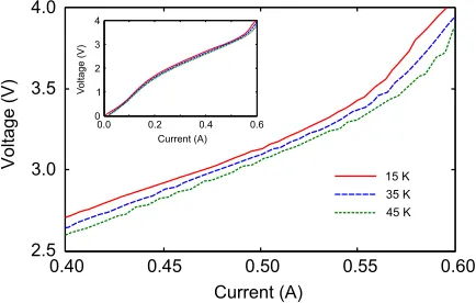
Fig. 2. Measured IV characteristics atT0 = 15, 35 and 45 K. Inset: IV charac-teristics including current ranges over which the QCL does not lase. Polynomial coefficients of Eq. (12) for use in Eq. (4) were derived from the measured IV data set.
self-heating in cw operation. Further, any changes in excitation such as steps or ramps create thermal transients [27]–[29] that disturb the thermal circuit’s equilibrium. Therefore in addition to three rate equations, a thermal model capable of predicting AR temperature must be included, and is represented by Eq. (4) in our equation set. This equation models the first order ther-mal behavior of the QCL and produces dynamic temperature response required to determine the temperature-sensitive RRE parameters at each step taken by the RRE solver. In Eq. (4), m represents the effective mass of the laser, cp the effective specific heat capacity of the laser material in J kg−1 K−1 and Rththe effective thermal resistance in K W−1 between the AR and submount, which in this model is assumed to be at the same temperature as the cryostat’s cold finger. The symbolT0 is the temperature, in kelvin, of the cold finger which is usually (but not necessarily) constant.
Although the RREs are expressed in terms of a current forcing function I(t), terminal voltage V(t) is also required by the equations for two reasons: (i) calculation of self heating within the AR, as expressed in Eq. (4) and (ii) calculation of each of the ever-changing voltage-dependent RRE parameters. With I(t) as the independent variable,V(t)may be calculated from the temperature-dependent current–voltage (IV) characteristics of the QCL, shown in Fig. 2. This can be done via a behavioral (or other) model ofV(t)expressed in terms ofI(t)andT(t). QCLs have IV characteristics somewhat different to, and more difficult to model theoretically, than those of diode lasers. For maximum accuracy we opted for a behavioral model based on measured temperature-dependent IV data, rather than use theoretically predicted IV characteristics.
Initial values for carrier and photon populations, the current forcing functionI(t), andT0, serve as independent inputs to the RREs (1)–(4). Given these inputs, the RREs may be solved for carrier and photon populations. The optical output powerP(t) can then be found from the photon population by [20]:
P(t) =η0ωS(t)/τp, (5)
whereη0is the power output coupling efficiency,is the reduced Planck constant, andωis the laser’s angular emission frequency.
The definition ofη0is [20]: η0 = (1−R1)
√
R2
(1−R1)√R2+ (1−R2)√R1
αm
αm+αw, (6)
whereR1 is the front facet mirror reflectivity,R2 the rear facet mirror reflectivity,αwthe waveguide loss andαmthe mirror loss defined as [21]:
αm =−ln(2RL1R2), (7)
where L is the length of the laser. We calculated the sponta-neous emission lifetimeτspfrom the dipole matrix elementz32 using [21]:
τsp=8π2εq02neffzλ3 2 32
, (8)
where λ is the wavelength of emission andneff the refractive index of the medium. The photon lifetimeτpis calculated from the modal loss via:
τp= c(αneff
w+αm) (9)
Values for the various constants appearing in Eqs. (1)–(7) are given in Table I. Device-specific constants pertaining to our exemplar QCL are indicated by daggers in the table, and would need to be re-calculated for any new laser structure.
C. RRE Parameter Modeling
To determine the temperature- and voltage-dependent RRE parameters, a thermally-balanced self-consistent Schr¨odinger Poisson (SP) RE scattering transport model [30]–[32] for all states in the device was applied in a grid of 13 temperatures and 38 electric field (voltage) values. From these calculations we extracted values for the RRE parameters gain factorG(T, V), ULL and LLL carrier lifetimesτ3(T, V)andτ21(T, V), injec-tion efficiencies into these levels η3(T, V) andη2(T, V), the scattering timeτ32(T, V)between them, and the dipole matrix elementz32(T, V)which is used in Eq. (8) for the calculation ofτsp(T, V). This yielded 494(T, V)grid point values for each of the seven RRE parameters, giving 3458 data values in total.
A well-understood limitation of RE models of QCLs is the prediction of hybridized wave functions extending between peri-ods of the QCL at certain biases [33], resulting in unrealistically large scattering rates being produced. All such non-physical parameters were identified and removed from the data set.
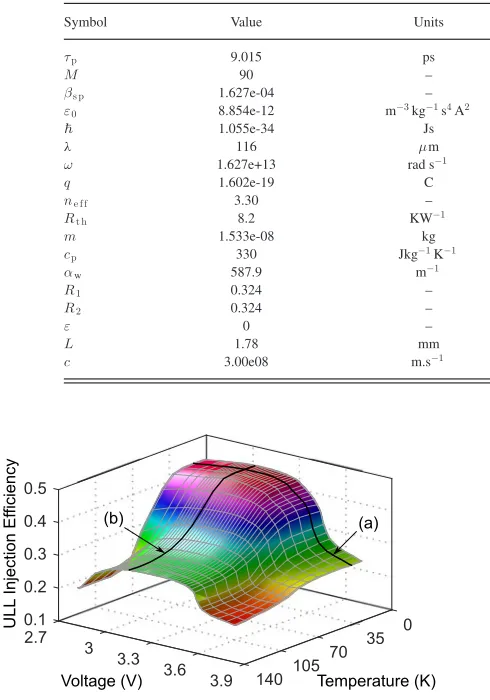
The plot of an example temperature- and voltage-dependent RRE parameter,η3, is shown in Fig. 3.
TABLE I
VALUE OFCONSTANTSUSED INEQS. (1)–(7)
Symbol Value Units Meaning (†indicates device-specific)
τp 9.015 ps †Photon lifetime in cavity
M 90 – †Number of periods in QCL structure
βs p 1.627e-04 – †Spontaneous emission factor
ε0 8.854e-12 m−3kg−1s4A2 Permittivity of free space
1.055e-34 Js Reduced Planck constant
λ 116 μm †Wavelength of emission
ω 1.627e+13 rad s−1 †Angular frequency of emission
q 1.602e-19 C Charge on the electron
ne f f 3.30 – †Effective refractive index of the medium
Rt h 8.2 KW−1 †Thermal resistance between active region and submount
m 1.533e-08 kg †Mass of laser chip
cp 330 Jkg−1K−1 †Effective specific heat capacity of laser chip
αw 587.9 m−1 †Waveguide loss
R1 0.324 – †Front facet mirror reflectivity
R2 0.324 – †Rear facet mirror reflectivity
ε 0 – †Gain compression factor
L 1.78 mm †Length of laser chip cavity
c 3.00e08 m.s−1 Speed of light in a vacuum
Fig. 3. Representation ofη3 as a surface, showing temperature and voltage dependence. Fall off inη3 with increasing drive current occurs much more rapidly with voltage [trace (a)] than temperature [trace (b)], making it the primary cause of roll-over in this QCL.
least-squares method to give simple and smooth RRE parameter functions.
The general form of a polynomial in two independent variables is:
Z(x, y) =
i,j
aijxiyj, (10)
where i andj are permuted subject to (i+j)≤k, and k is the order of the polynomial. The general third order polynomial expanded for variablesT andV (in lieu ofxandy) is:
Z(T, V) =a00+a10T+a01V +a11T V +a20T2+a02V2
+a21T2V +a12T V2+a30T3+a03V3 (11)
Table II lists coefficient values for each of the temperature-and voltage-dependent RRE parameters found in (11). Termi-nal voltageV(t)was modeled by fitting a third order polyno-mial of the following form to measured temperature-dependent
current–voltage data:
V(I, T) =a00+a10I+a01T +a11IT +a20I2+a02T2
+a21I2T+a12IT2+a30I3+a03T3 (12)
[image:4.594.58.303.93.443.2]Coefficient values for this V(t) model are also given in Table II.
D. Solution Process
The derivation of RRE parameters from full REs, fitting of polynomials to RRE data, and calculation of other structure-dependent items indicated in Table I, are a once-off process for each QCL structure. Once done, (1)–(4) may then be repeatedly solved for any chosen current excitation waveform and cold finger temperature. As with any ordinary differential equation (ODE) set, our equations, including the thermal model, have to be solved concurrently. While the solution is in progress,V(t)is continuously re-calculated using Eq. (12) at every step the solver takes. The result is then fed into Eq. (4) to produce the time-dependent AR temperatureT(t). During this processV(t)and T(t)are simultaneously fed into the polynomial coefficients of all seven temperature- and voltage-dependent RRE parameters to update them. We used a well-known commercial ODE solver, Matlab’s ode23s function, to produce the results following.
III. RESULTS ANDDISCUSSION
A. Static Behavior
TABLE II
POLYNOMIALCOEFFICIENTVALUES FORMODELINGVOLTAGE ANDTEMPERATUREDEPENDENTRRE PARAMETERS
Coefficient M G η3 η2 τ3 τ3 2 τ2 1 z3 2 V
a0 0 +2.5488e+04 +2.1969e-01 +6.7728e-03 +9.0220e-12 +1.9093e-10 +1.7446e-11 +6.0916e-09 −1.6880e-01
a1 0 −5.3919e+02 +2.5332e-03 −1.1661e-04 +2.1018e-14 +1.8410e-12 +9.7705e-14 +1.8713e-11 +1.4024e+01
a0 1 −4.1768e+04 −3.8617e+00 +1.9358e-02 +1.6585e-11 +4.7689e-10 −4.1352e-11 −8.4710e-09 −8.5203e-03
a1 1 +2.7624e+02 −3.3045e-03 +8.5813e-05 −1.3866e-14 −7.5783e-13 +6.3343e-14 −1.4355e-11 −1.2368e-03
a2 0 +5.6842e+00 −5.0512e-05 +1.2107e-06 −2.0161e-16 −3.9381e-14 −2.7574e-15 −3.4844e-13 −2.7018e+01
a0 2 +2.1376e+04 +2.6028e+00 −1.3166e-02 −9.2287e-12 −2.7523e-10 +2.3966e-11 +5.2504e-09 +1.6206e-04
a2 1 −1.8228e+00 +4.9878e-06 −6.7085e-07 +7.1827e-17 +5.6953e-15 −3.7009e-16 +5.7916e-14 +1.2415e-02
a1 2 −3.0596e+01 +8.7604e-04 −1.4093e-05 +2.5180e-15 +1.2665e-13 −1.4482e-14 +3.1195e-12 −1.2573e-04
a3 0 −1.4067e-02 +6.6497e-08 +1.8192e-08 −2.9601e-18 +4.2429e-17 +5.4384e-18 +3.4461e-16 +2.6099e+01
[image:5.594.56.262.153.506.2]a0 3 −2.8677e+03 −4.2682e-01 +2.1744e-03 +1.1832e-12 +3.7335e-11 −3.2744e-12 −7.8057e-10 −1.2635e-06
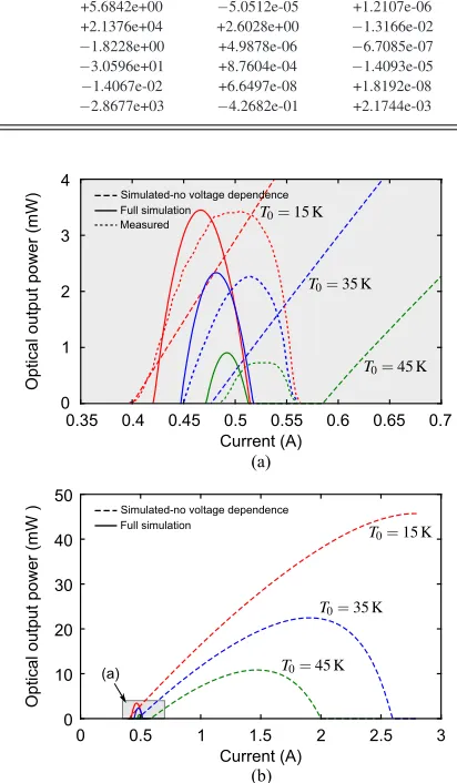
Fig. 4. Effect of RRE parameter voltage-dependence on LI characteristics. In part (a), solid lines are LI simulations with voltage dependent RRE parameters at
T0 =15 K, 35 K and 45 K. Dotted lines are measured characteristics of the QCL at some of the same temperatures, vertically scaled by a factor of approximately four to compensate for the poor efficiency of the collection equipment. Dashed lines in parts (a) and (b) show LI simulations at the same temperatures, but with voltage-dependence of RRE parameters suppressed (parameters values locked atV =2.80 V). Roll over observed in part (b) is thus thermal-only (i.e. due only to temperature-dependence of RRE parameters).
35 K, and 45 K, producing the results shown as solid curves in Fig. 4(a). Measured characteristics at some of the same cold finger temperatures, for comparison, are shown as dotted traces. The measured data were reduced in magnitude by a factor of approximately four due to the low collection efficiency of the detection optics. The data shown in Fig. 4(a) has been rescaled to match the simulated curves, for easy comparison. We are not aware of any other THz QCL model, to date, which is able to correctly predict roll-over behavior in QCLs.
As a demonstration of the part played by active region volt-age in roll-over behavior, we repeated the simulation using RRE
parameters that were temperature- but not voltage-dependent. This was done by assigning a constant value ofV =2.80 V in all RRE parameters, effectively making them voltage-independent. The results are shown as dashed lines in Fig. 4(a) and (b). Although threshold occurs at almost the same points as for the previous simulation, the LI curves are many times broader, with the resulting thermal-only roll-over occurring at far higher currents, demonstrating electric field effects to be the primary cause of roll-over in this type of device. Although the voltage-dependence of RRE parameters was suppressed in this sim-ulation, V(t)continued to be calculated via Eq. (12) for use in Eq. (4). We have previously reported the “full simulation” LI characteristics of this QCL [23], and reproduce them here for comparison with the hypothetical case of “non-voltage-dependent” RRE parameters.
The physical cause of voltage-related roll-over is a misalign-ment between the injector and ULL at higher voltages [34], that manifests as a rapid drop in injection efficiencyη3. Fig. 3 clearly shows that near roll-overη3drops far more rapidly due to voltage change (see trace (a) in Fig. 3) than due to temperature change [trace (b)].
B. Dynamic Behavior
Fig. 5. Effect of cold finger temperature on step response. Response of the QCL to a current step of 0.470 A for six cold finger temperatures (color online) is shown, with both temperature- voltage-dependence of RRE parameters invoked. Both turn-on delay and pulse rise times increase with increasing cold finger temperature.
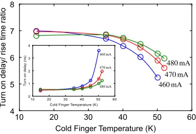
Fig. 6. Dependence of optical output power rise time on temperature for current step excitations of 460, 470, and 480 mA. Circles indicate data points, with curves to guide the eye.
Fig. 7. Relation of turn-on delay and rise time. Inset: turn-on delay as a function of temperature for three currents. Circles indicate data points, with curves to guide the eye.
[image:6.594.59.278.277.417.2]against temperature at pulse amplitudes of 460 mA and 480 mA (also shown in Fig. 6). In addition, turn-on delay was calculated for all simulations and is seen to correlate with rise time, as shown in Fig. 7. The sharp increase in both rise time (describing the speed of the system approaching saturation) and delay time (required for spontaneous emission to build up to a noticeable
Fig. 8. Effect of cold finger temperature on 0.47 A step current response when voltage-dependence of RRE parameters is suppressed (values fixed for
V =3.00 V)—shown as dashed lines. For reference, solid lines (identical to those of Fig. 5) are responses with voltage-dependence invoked. Temperature-and voltage-dependence of RRE parameters is thus seen to have a significant effect on both turn-on delay and pulse rise time.
value), displayed in Fig. 6 and inset of Fig. 7, comes from the fast decrease of small-signal gain as the temperature increases. Their ratio does change somewhat with temperature (Fig. 7), but by a much smaller factor than they do individually. With the initial turn-on gain much larger than the saturated (or threshold) gain, one can expect that higher-order, more lossy modes will also temporarily exist before the laser stabilizes in the single mode of operation in steady state. However, this effect was not included in the present model.
To assess the impact of RRE parameter voltage-dependence on the behaviors shown in Fig. 5, we then repeated the simulation with voltage-dependence suppressed. This was done by assign-ing a constant voltage valueV = 3.00V in Eq. (11), the RRE polynomials. In other equations, i.e. Eqs. (12) and (4), use of temperature- and current-dependent voltage was retained. Non-voltage-dependent results are shown in Fig. 8 as dashed lines and, for comparison, voltage-dependent results as solid lines. The results demonstrate a significant difference when voltage is not taken into account, and agree only near the temperature at which the terminal voltage is actually 3.00 V.
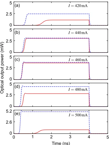
[image:6.594.72.264.477.609.2]Fig. 9. Effect of RRE parameter voltage dependence on pulse response for constant cold finger temperatureT0 =15 K and varying current drive. Parts (a)– (e) show QCL’s response to five rectangular current pulses of amplitude 420, 440, 460, 480, and 500 mA. Solid lines represent the response with voltage-dependence of RRE parameters invoked and broken lines the response for voltage-dependence suppressed (for constantV =3.00 V). Progressing from (a) to (e), peak optical power shown by the solid curves is seen to first rise and then fall, in accordance with the roll-over mechanism. For the broken curves it keeps rising due to the absence of the voltage-related roll-over mechanism.
figure), the times reduce to optimum values at about 460 mA and then lengthen again as injection efficiencyη3 rapidly falls off with increasing current. Optical power output follows the same trend, peaking at∼460 mA and falling off rapidly just before cut-off (part(e) of the figure). When voltage-dependence of the RRE parameters is suppressed in the same way as before, however, response times continue shortening and optical power continues growing (broken lines in Fig. 9). Reduction in optical output power then peaks well after the known cut-off current of the QCL (not shown in figure), due to thermal-only effects, and in accordance with the LI characteristics of Fig. 4(b).
IV. CONCLUSION
We have presented a complete, computationally simple, dy-namic model of an exemplar BTC THz QCL that behaves realistically over a wide range of voltages and temperatures. Our simulations reveal temperature- and bias-dependent turn-on characteristics that would be of interest in typically high speed free space communications and pulsed applications. They also demonstrate the importance of temperature- and voltage-dependence modeling, which has an impact on device behavior on timescales from pico-seconds to static. The novelty of our
approach is the use of RRE parameters that are functions of device voltage and lattice temperature, derived from first prin-ciples by SP solution of the full set of REs. Coupled with a time dependent thermal equation, we obtain an RRE model that is valid over a broad range of device temperatures and voltages, allowing exploration of a QCL’s characteristics over its full op-erating range of bias currents and temperatures. Although the RRE parameters presented here were derived for an exemplar BTC device, the approach is generic and may be applied to any QCL by extracting appropriate parameters from a full RE model.
REFERENCES
[1] B. S. Williams, “Terahertz quantum-cascade lasers,” Nature Photon., vol. 1, pp. 517–525, 2007.
[2] R. Martini et al., “Free-space optical transmission of multimedia satellite data streams using mid-infrared quantum cascade lasers,” Electron. Lett., vol. 38, no. 4, pp. 181–183, 2002.
[3] R. Martini and E. A. Whittaker, “Quantum cascade laser-based free space optical communications,” J. Opt. Fiber. Commun. Rep., vol. 2, no. 4, pp. 279–292, 2005.
[4] F. Capasso et al., “Quantum cascade lasers: Ultrahigh-speed opera-tion, optical wireless communicaopera-tion, narrow linewidth, and far-infrared emission,” IEEE J. Quantum Electron., vol. 38, no. 6, pp. 511–532, Jun. 2002.
[5] Z. Chen et al., “Wireless communication demonstration at 4.1 THz using quantum cascade laser and quantum well photodetector,” Electron. Lett., vol. 47, no. 17, pp. 1002–1004, 2011.
[6] S. Barbieri et al., “13 GHz direct modulation of terahertz quantum cascade lasers,” Appl. Phys. Lett., vol. 91, no. 14, 2007, Art. no. 143510. [7] M. Tonouchi, “Cutting-edge terahertz technology,” Nature Photon.,
vol. 1, no. 2, pp. 97–105, 2007.
[8] R. K¨ohler et al., “Terahertz semiconductor-heterostructure laser,” Nature, vol. 417, no. 6885, pp. 156–159, 2002.
[9] M. Wienold et al., “High-temperature, continuous-wave operation of ter-ahertz quantum-cascade lasers with metal-metal waveguides and third-order distributed feedback,” Opt. Express, vol. 22, no. 3, pp. 3334–3348, 2014.
[10] S. Fathololoumi et al., “Terahertz quantum cascade lasers operating up to 200 k with optimized oscillator strength and improved injection tunnel-ing,” Opt. Express, vol. 20, no. 4, pp. 3866–3876, 2012.
[11] L. Li et al., “Terahertz quantum cascade lasers with>1 W output powers,”
Electron. Lett., vol. 50, no. 4, pp. 309–311, 2014.
[12] G. Giuliani, M. Norgia, S. Donati, and T. Bosch, “Laser diode self-mixing technique for sensing applications,” J. Opt. A: Pure Appl. Opt., vol. 4, no. 6, pp. 283–294, 2002.
[13] S. Donati, “Responsivity and noise of self-mixing photodetection schemes,” IEEE J. Quantum. Electron., vol. 47, no. 11, pp. 1428–433, Nov. 2011.
[14] T. Taimre et al., “Laser feedback interferometry: A tutorial on the self-mixing effect for coherent sensing,” Adv. Opt. Photon., vol. 7, no. 3, pp. 570–631, 2015.
[15] A. D. Raki´c et al., “Swept-frequency feedback interferometry using ter-ahertz frequency QCLs: A method for imaging and materials analysis,”
Opt. Express, vol. 21, no. 19, pp. 22194–22205, 2013.
[16] G. Agnew et al., “Model for a pulsed terahertz quantum cascade laser under optical feedback,” Opt. Express, vol. 24, no. 18, pp. 20554–20570, 2016.
[17] S. Donati and M. T. Fathi, “Transition from short-to-long cavity and from self-mixing to chaos in a delayed optical feedback laser,” IEEE J. Quantum
Electron., vol. 48, no. 10, pp. 1352–1359, Oct. 2012.
[18] S. Donati and R. Horng, “The diagram of feedback regimes revisited,”
IEEE J. Sel. Topics Quantum Electron., vol. 19, no. 4, Jul./Aug. 2012, Art.
no. 1500309.
[19] Y. Petitjean, F. Destic, J. C. Mollier, and C. Sirtori, “Dynamic modeling of terahertz quantum cascade lasers,” IEEE J. Sel. Topics Quantum Electron., vol. 17, no. 1, pp. 22–29, Jan./Feb. 2011.
[20] A. Hamadou, J. L. Thobel, and S. Lamari, “Modelling of temperature effects on the characteristics of mid-infrared quantum cascade lasers,”
[21] A. Hamadou, S. Lamari, and J. L. Thobel, “Dynamic modeling of a mid-infrared quantum cascade laser,” J. Appl. Phys., vol. 105, no. 9, 2009, Art. no. 093116.
[22] K. S. C. Yong, M. K. Haldar, and J. F. Webb, “An equivalent circuit for quantum cascade lasers,” J. Infrared Millimeter Terahertz Waves, vol. 34, no. 10, pp. 586–597, 2013.
[23] G. Agnew et al., “Efficient prediction of terahertz quantum cascade laser dynamics from steady-state simulations,” Appl. Phys. Lett., vol. 106, no. 16, 2015, Art. no. 161105.
[24] S. Han et al., “Laser feedback interferometry as a tool for analysis of gran-ular materials at terahertz frequencies: Towards imaging and identification of plastic explosives,” Sensors, vol. 16, no. 352, pp. 1–9, 2016. [25] Y. L. Lim et al., “High-contrast coherent terahertz imaging of porcine
tis-sue via swept-frequency feedback interferometry,” Biomed. Opt. Express, vol. 5, no. 11, pp. 3981–3989, 2014.
[26] S. P. Khanna et al., “The growth and measurement of terahertz quantum cascade lasers,” Phys. E, vol. 40, no. 6, pp. 1859–1861, 2007.
[27] A. Valavanis et al., “Time-resolved measurement of pulse-to-pulse heating effects in a terahertz quantum cascade laser using an NbN superconducting detector,” Appl. Phys. Lett., vol. 103, no. 6, 2013, Art. no. 061120. [28] M. S. Vitiello, G. Scamarcio, and V. Spagnolo, “Time-resolved
measure-ment of the local lattice temperature in terahertz quantum cascade lasers,”
Appl. Phys. Lett., vol. 92, no. 10, 2008, Art. no. 101116.
[29] R. L. Tober, “Active region temperatures of quantum cascade lasers during pulsed excitation,” J. Appl. Phys., vol. 101, 2007, Art. no. 044507. [30] P. Harrison and A. Valavanis, Quantum Wells, Wires and Dots: Theoretical
and Computational Physics of Semiconductor Nanostructures, 4th ed.
New York, NY, USA: Wiley, 2016.
[31] D. Indjin, P. Harrison, R. W. Kelsall, and Z. Ikoni´c, “Self-consistent scat-tering theory of transport and output characteristics of quantum cascade lasers,” J. Appl. Phys., vol. 91, no. 11, pp. 9019–9026, 2002.
[32] V. D. Jovanovi´c et al., “Influence of doping density on electron dynamics in GaAs/AlGaAs quantum cascade lasers,” J. Appl. Phys., vol. 99, no. 10, 2006, Art. no. 103106.
[33] H. Callebaut and Q. Hu, “Importance of coherence for electron transport in terahertz quantum cascade lasers,” J. Appl. Phys., vol. 98, no. 10, 2005, Art. no. 104505.
[34] S. S. Howard, Z. Liu, and C. F. Gmachl, “Thermal and stark-effect roll-over of quantum-cascade lasers,” IEEE J. Quantum Electron., vol. 44, no. 4, pp. 319–323, Apr. 2008.
[35] K. Petermann, Laser Diode Modulation and Noise. Dordrecht, The Nether-lands: Kluwer, 1991.
Gary Agnew (M’93) received the B.Sc. and M.Sc. degrees in electrical engineering from the University of the Witwatersrand, Johannesburg, South Africa, in 1985 and 1990, respectively. He is currently working toward the Ph.D. degree at the University of Queens-land, Brisbane, Australia. He has held a number of research positions in the instrumentation industry, working on microwave, photonic, and nucleonic sen-sor technology. His research interests include model-ing terahertz quantum cascade lasers.
Andrew Grier was born in Belfast, U.K. He received the B.Sc. (Hons.) degree in physics from the University of St. Andrews, St. Andrews, U.K., in 2009, and the M.Sc. and Ph.D. degrees in electronic and electrical engineering from the University of Leeds, Leeds, U.K., in 2010 and 2015, respectively. He is currently a Senior Research and Development Engineer at Seagate Technology, Dublin, Ireland. His research interests include computational modeling of carrier transport in semiconductor quantum electronics, and stochastic micromagnetic modeling of advanced magnetic recording devices.
Thomas Taimre received the B.Sc. degree in math-ematics and statistics in 2003, the B.Sc. degree (with first honors) in statistics in 2004, and the Ph.D. de-gree in mathematics in 2009, all from the Univer-sity of Queensland, Brisbane, Australia. He is a Lec-turer of mathematics and statistics at the University of Queensland. He coauthored the book entitled
Hand-book of Monte Carlo Methods, which provides a
hands-on guide to the theory, algorithms, techniques, and applications of Monte Carlo methods. His current research interests include the interface of probability theory, computer simulation, and mathematical optimization with biological and other scientific, engineering, and finance disciplines, including within laser feedback interferometry.
Karl Bertling (S’06–M’12) received the B.E. de-gree in electrical engineering and the B.Sc. dede-gree in physics in 2003, the M.Phil. degree in electrical engineering in 2006, and the Ph.D. degree in elec-trical engineering in 2012, all from the University of Queensland, Brisbane, Australia. His current research interests include imaging and sensing via laser feed-back interferometry (utilizing the self-mixing effect). He has contributed to the body of knowledge for this technique, in visible, near-IR, mid-IR, and terahertz semiconductor lasers.
Yah Leng Lim received the B.Eng. and Ph.D. degrees in electrical engineer-ing from the University of Queensland, Brisbane, Australia, in 2001 and 2011, respectively. From 2002 to 2005, he was an R&D Engineer with the Philips Optical Storage (Singapore), where he worked on the integration of optical and sensor technologies in optical storage systems. He currently holds an Advance Queensland Research Fellowship funded by the Queensland Government, fo-cusing on the development of laser feedback interferometry imaging systems for the early detection of skin cancers.
Zoran Ikoni´c received the Ph.D. degree in electrical engineering from the University of Belgrade, Bel-grade, Serbia, in 1987. During 1981–1999, he was with the Faculty of Electrical Engineering, University of Belgrade. Since 1999, he has been with the School of Electronic and Electrical Engineering, University of Leeds, Leeds, U.K. His current research interests include electronic structure and optical and trans-port properties of semiconductor nanostructures and devices.
Alexander Valavanis received the M.Eng. (Hons.) degree in electronic engineering from the University of York, York, U.K., in 2004, and the Ph.D. degree in electronic and electrical engineering from the Uni-versity of Leeds, Leeds, U.K., in 2009. From 2004 to 2005, he was an Instrumentation Engineer with STFC Daresbury Laboratories, Warrington, U.K., and from 2009 to 2016, he was a Research Fellow at the Univer-sity of Leeds. He is currently a UniverUniver-sity Academic Fellow (tenure track) in terahertz instrumentation at the University of Leeds. His research interests include terahertz instrumentation, quantum cascade lasers, silicon photonics, and com-putational methods for quantum electronics. He is a member of the Institution of Engineering and Technology.
Paul Harrison is the Pro Vice-Chancellor for Re-search and Innovation at Sheffield Hallam Univer-sity, Sheffield, U.K., where he also a member of the Materials and Engineering Research Institute. His re-search interests include the theoretical and computa-tional physics of semiconductor nanostructures.
Dragan Indjin received the B.S., M.S., and Ph.D. degrees in electrical engineering from the University of Belgrade, Belgrade, Serbia.
He joined the Faculty of Electrical Engineering, University of Belgrade, in 1989, where he later be-came an Associate Professor. Since 2001, he has been with the Institute of Microwaves and Photon-ics, School of Electronic and Electrical Engineer-ing, University of Leeds, Leeds, U.K., where he is a Reader (Associate Professor) in optoelectronics and nanoscale electronics. His research interests include the electronic structures, optical and transport properties, optimization and de-sign of quantum wells, superlattices, quantum-cascade lasers, and quantum-well infrared photodetectors from near- to far-infrared and terahertz spectral ranges. He is currently focused on applications of quantum-cascade lasers and interband cascade lasers for sensing and imaging applications.
Dr. Indjin received the Prestigious Academic Fellowship from the Institute of Microwaves and Photonics, School of Electronic and Electrical Engineering, University of Leeds, in 2005. He is currently the coordinator of major interna-tional projects on infrared and terahertz imaging and sensing for medical and security application.