This is a repository copy of The combined effect of surface texturing and DLC coating on the functional properties of internal combustion engines.
White Rose Research Online URL for this paper: http://eprints.whiterose.ac.uk/133720/
Version: Accepted Version
Article:
Koszela, W, Pawlus, P, Reizer, R et al. (1 more author) (2018) The combined effect of surface texturing and DLC coating on the functional properties of internal combustion engines. Tribology International, 127. pp. 470-477. ISSN 0301-679X
https://doi.org/10.1016/j.triboint.2018.06.034
© 2018 Elsevier Ltd. This manuscript version is made available under the CC-BY-NC-ND 4.0 license http://creativecommons.org/licenses/by-nc-nd/4.0/.
[email protected] https://eprints.whiterose.ac.uk/ Reuse
This article is distributed under the terms of the Creative Commons Attribution-NonCommercial-NoDerivs (CC BY-NC-ND) licence. This licence only allows you to download this work and share it with others as long as you credit the authors, but you can’t change the article in any way or use it commercially. More
information and the full terms of the licence here: https://creativecommons.org/licenses/
Takedown
If you consider content in White Rose Research Online to be in breach of UK law, please notify us by
The combined effect of surface texturing and DLC coating on the functional properties of internal combustion engines
WaldemarKoszelaa, Pawel Pawlusa*, Rafal Reizerb, Tomasz Liskiewiczc
* corresponding author, tel. +48-178651183, fax +48-178651183, email: [email protected]
a Rzeszow University of Technology, 35-959 Rzeszow, Powstancow Warszawy 12, Poland
b University of Rzeszow, 35-959 Rzeszow, Tadeusza Rejtana 16 C, Poland
c University of Leeds, Leeds LS2 9JT, UK
Abstract
A reduction in frictional loss is an important aspect of efficiency in high-performance internal combustion engines. This can be achieved by the well-designed surface texturing of the cylinder bore, which can reduce friction at the ring/bore interface. In this work, dimples were created using plastic deformation on the cylinder surfaces of high-performance motorcycle engines. Prior to texturing, these cylinders had Nikasil coating. One cylinder was subjected to the deposition of DLC coating and then surface texturing. The results of the functional performance of internal combustion engines with textured cylinder surfaces were compared to untextured ones. The engine performance was analysed in terms of maximum power and maximum torque output. The results showed that cylinder surface texturing improved the functional properties of internal combustion engines. The maximum power increased by up to 5.8%. Best performance was achieved for internal combustion engines with textured cylinders and DLC coating. Such surface modification allows the powering of the motorbike with higher maximum speed and provides better vehicle dynamics at high speeds.
Keywords: cylinder, surface texturing, DLC coating, internal combustion engine
Nomenclature:
TDC – top dead centre BDC – bottom dead centre DLC – diamond-like carbon
PECVD – plasma enhanced chemical vapour deposition PVD – physical vapour deposition
HP – horse power
IC – internal combustion
Ra – arithmetic mean deviation of roughness profile, µm Spd – density of peaks, 1/mm2
Sq – root mean square height of surface, m Str – texture–aspect ratio
1. Introduction
The achievements of professional riders in motor sports depend primarily on their equipment.
For riders of similar skills, a minor change in the operating parameters of their internal
combustion engine (power and torque) can decide the outcome between winning and losing.
The subjection of high-performance engines to extreme loadings decreases their useful life;
therefore, the application of the best construction solutions, materials and machining methods
is necessary. Most solutions applied in motor sports are eventually introduced in mass
production.
A reduction in frictional loss is an important issue in order to meet the requirements of high
efficiency in internal combustion (IC) engines. The application of surface texturing and
advanced coatings is the main avenue towards minimising frictional losses in IC engines in
passenger cars [1]. The piston ring–cylinder pack contributes significantly to the sum of
frictional losses of the IC engine. Surface texturing can be used to reduce the friction between
sliding elements. Dimples act as additional reservoirs for oil and traps for wear particles;
therefore, their presence can improve the friction and wear resistance of tribological assemblies.
The surface texturing of cylinder liners can cause the reduction of friction of the piston ring –
cylinder assembly. Simulations have shown that cylinder liner texturing (contrary to piston ring
texturing) can lead to a steady positive effect on friction under starved lubrication [2]. Starved
lubrication occurs for the minimum supply of a lubricant to the contact zone, while under the
fluid lubrication regime an oil film completely separates sliding surfaces. Textured cylinder
liners can cause a decrease in fuel and oil consumption in IC engines. Zhou et al. [3] reported
on the basis of theoretical models that circular dimple patterns between the top dead centres of
the cylinder liner surface increased oil film thickness. The use of various laser surface texturing
patterns to different cylinder liner regions could improve the functional properties of IC
engines, like fuel and oil consumption [4]. An analytical model of the contact between a piston
ring and a textured cylinder liner was developed [5]. It was found that for a barrel-shaped ring,
the presence of dimples on the cylinder liner surface could generate additional load-carrying
capacity. Tang et al. [6] used a flat steel surface of increased hardness over a textured steel
surface under reciprocating sliding and reported a reduction in friction and wear due to the
application of dimples with a pit-area ratio (the area occupied by the dimples) of 5%. Yin et al.
[7] studied numerically the effect of cylinder liner texturing on lubrication in a diesel engine.
of 0.03–0.1. Usman and Park [8] developed a model of mixed lubrication in order to study the
influence of liner texturing on the contact performance of the piston ring pack under warm
engine conditions. Grooves normal to the sliding direction were found to improve the conditions
for hydrodynamic lubrication, while micro-dimples were found to support the lubrication at the
piston reversals. Vladescu et al. [9] investigated the effect of surface texturing on oil film
thickness and friction force under conditions resembling those in the piston ring–cylinder liner
pack. It was found that the presence of cavities led to an increase in the fluid film thickness and
a decrease in the friction force (up to 41%) under the mixed lubrication regime. It has been
shown that under full lubrication, the surface texture caused a reduction in film thickness and a
small increase in friction force [9]. Grabon et al. achieved a large friction reduction under the
fluid lubrication regime due to cylinder liner surface texturing; however, they showed that the
effect of the presence of dimples on the coefficient of friction under the starved lubrication
regime was negligible [10]. The numerical results indicated that the ring profile determined if
cylinder surface texturing was beneficial or not. For quasi-conformal contact, a friction
reduction of up to 70% is possible due to surface texturing. For non-conformal contact,
however, the presence of cavities on the cylinder surface is harmful [11].
Laser texturing is the most common method for the creation of dimples [4, 7, 9]. This method
is accessible, precise and easy. An increase in temperature observed in dimple areas is the
biggest disadvantage of this method and limits its applicability to coated sliding elements.
Following the laser texturing removal of burrs, further machining operation is required.
Different methods of texturing, like burnishing (embossing) [10, 12, 13, 14], mechanical
polishing, honing [15, 16, 14, 18], etching, abrasive jet machining [19, 20] or a combination
of these methods, are also possible [21]. It is not difficult to create dimples of comparatively
large dimensions, applied for example in the sleeves of slide bearings, contrary to the
micro-dimples formed on thin-walled or coated elements.
A type of physical vapour deposition (PVD) coatings, which was applied successfully in motor
vehicles, is called diamond-like carbon (DLC). DLC coating essentially consists of a mix of
diamond and graphite. Different types of DLC coatings can be used, such as pure DLC,
metal-doped and carbide-metal-doped. Non-metal-doped DLC coatings are divided into hydrogen-free and
hydrogenated. The properties of doped hydrogenated DLC coatings depend on the dope
material [22]. The introduction of DLC coatings opened additional possibilities in improving
friction, very good anti-wear properties, resistance to seizure, highly elastic modulus and
hardness, good corrosion resistance, and high thermal and chemical stability [22, 23].
It was found that Me-C:H PVD coatings on the piston ring performed better than other
solutions, particularly in regard to the wear rate of the cylinder liner [15]. Mobarak et al. [24]
studied experimentally the tribological behaviour of hydrogenated amorphous carbon (a-C: H)
DLC coating using a four-ball tribotester. It was found that wear and the coefficient friction
was reduced after the application of DLC coating compared to the use of uncoated stainless
steel.
The tribological performance of various coatings, including DLC coating, on nitrided and
chrome-plated stainless steel piston rings was studied by Tung et al. [15]. The experimental
results showed that DLC coating led to the lowest wear of the cast iron cylinder liner.
Boundary lubricated tribological tests were carried out under reciprocating sliding [26]. It was
found that W-containing DLC coatings substantially improved the tribological performance.
Tribological tests were conducted using a reciprocating tester [27]. A detail of the cylinder
block co-acted with a segment of the piston ring. Several coatings on the ring sample were
applied (TiN, Cr-ceramic and TiAlN, and DLC). The results showed that the DLC coating led
to the best tribological performance of the tested sliding pair.
The application of DLC coating for cylinder liners caused a reduction of the coefficient of
friction by 19% during reciprocating laboratory tests. In addition, a substantial decrease in wear
and a decrease in a the specific fuel consumption of an IC engine by 2.5% were found after
DLC coating of cylinder liners compared with uncoated ones [28].
Nikasil coating was used first by Mahle in 1967 [29]. Nickel is the main component filling and
binding the silicon carbide. This layer is characterised by considerably higher hardness and
wear resistance than the substrate.
In this work, dimples were created on cylinders of high-performance motorcycle engines using
the plastic deformation method. The combined effect of surface texturing and DLC coating on
the functional properties of internal combustion engines was investigated.
2. Experimental details
For the correct evaluation of the effect of texturing on operating parameters, the cylinders of a
speedway motorcycle engine with honed Nikasil coating were modified. In a speedway, the
track is composed of two straight sections connected by smooth oval curves. The starting region
is divided into four equal portions. The length of the track must be between 260 and 425 meters,
while the width should be not smaller than 10 meters. All heats, typically consisting of four
laps, are run anti-clockwise [30]. Speed on the straight fragments of the track can exceed 100
km/h. The bike does not have brakes, and its weight should not be less than 77 kilograms. The
motorcycle, fuelled by methanol, uses a four-stroke, single-cylinder engine of a capacity up to
500 cm3.
The test object was a single-cylinder, four-stroke, spark-ignition engine. The tested engine was
air-cooled, its capacity was 498 cm3 with four valves on the cylinder head and an overhead
camshaft. One complete engine with five different cylinders was used for this research in the
engine test cell. Different engines with textured or untextured cylinders were used in
motorcycles during races.
Three cylinders textured with different intensity 1, 2, 3, one cylinder following surface texturing
and then DLC coating 4, and one reference untextured cylinder 0 were tested. The standard
cylinder was denoted as 0, while the textured cylinders as 1, 2, 3 and 4 respectively.
2.2. Surface texturing
The creation of dimples on inner cylinder surfaces affects the co-action of the piston ring pack,
which is responsible for mechanical losses in internal combustion engines.
Additional cavities were formed on plateau-honed cylinder bore surfaces. Plateau honing is a
type of surface texturing. A cross-hatched surface texture created during plateau honing is a
two-process texture resembling that obtained after the running in of an IC engine. It ensures
good sliding properties of smooth surfaces with a great ability to maintain oil in valleys of the
surface.
During the creation of dimples on the inner surface of the cylinder bore, plastic deformation of
the machined surface was applied. The head for dimples creationwas fitted to work in a vertical
milling machine controlling the pressure of the forming roller and the change in the diameter
of the machined cylinders [31]. The same pressure should be maintained along the whole bore
surface should be maintained because any fluctuation may change cylinder bore diameters and
the correct texturing process. This setting should be precisely controlled. Ceramic balls are the
working element of the dimple formation. The design of the head allows for the creation of
micro-dimples, the size of which depends on the adjustable pressure and diameters of the
forming balls. The pattern of micro-dimples on the cylinder surface depends firstly on the
design of the forming tool and secondly on the feed of the head. As a result of the change of the
feed, which is the fundamental machining parameter, spacing between machining paths can be
changed. Forming balls should be mounted to the roller with accuracy and precision. The
method whereby dimples are burnished on the machined surface using the forming roller
transforms the shapes of the forming balls and their array on the machining path. The textured
surfaces were located in each cylinder bore between the top dead centre (TDC) and the bottom
dead centre (BDC) of a piston.
It is possible to encounter difficulties in creating dimples for coated surfaces. Hard Nikasil
coating on aluminum alloy surfaces causes changes in the concept of dimples creation in
relation to homogeneous materials. During initial tests, these methods which caused coating
damage or delamination were excluded. As a result, cavities were mechanically created on
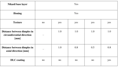
cylinders with Nikasil coating using forming elements of a spherical shape. Table 1 presents
the types of tested cylinders.
Table 1. Types of tested cylinders
Nikasil base layer Yes
Honing Yes
Texture no yes yes yes yes
Distance between dimples in circumferential direction
[mm]
–
1.0 1.0 1.0 1.0
Distance between dimples in
axial direction [mm] –
1.0 0.8 0.5 0.8
DLC coating no no no no yes
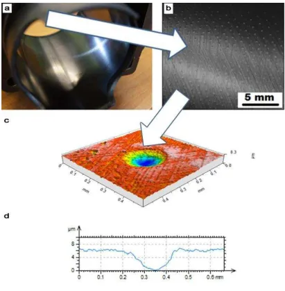
Figure 1 presents the machining effect of dimple creation. The surface topographies of the
cylinders were measured by white light interferometer Talysurf CCI Lite of 0.01 nm vertical
resolution and stylus profilometer Hommelwerke T8000. In optical measurement, the objective
5× was used, and the measuring area 3.29 × 3.29 mm contained 1024 × 1024 points. During
tactile measurement, the radius of the stylus tip was 2 µm, the measuring speed was 0.5 mm/s,
the sampling interval was 5 µm and the measuring area was 4 × 5 mm. In both kinds of
measurement, the form was removed using a polynomial of the 3rd degree. After optical
measurement, spikes were excluded by truncation.
As a result of machining, micro-dimples of 0.25–0.35 mm in diameter and 4–6 µm in depth
were obtained.
The obtained pits were mutually located at a distance of 1 mm in circumference and between
subsequent paths: 1 mm for cylinder 1, 0.8 mm for cylinders 2 and 4, and 0.5 mm for cylinder
3.
[image:8.595.72.529.67.325.2]Figure 1. Textured cylinder: a) view of the cylinder; b) surface morphology; c) 3D
representation of a single dimple; d) cross-section of a single dimple
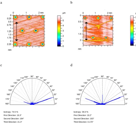
Figure 2 presents the contour plots and texture directions of cylinders 1 and 4 before tests. It is
evident from contour plots (Figures 2a and 2b) that the distance between dimples in the axial
direction is smaller for the cylinder from engine 4. The main surface directions, shown in
Figures 2c and 2d, resulted from honing. The honing angles were 32 and 36 degrees for
a b
[image:10.595.75.515.70.480.2]c d
Figure 2. Contour plots (a, b) and main surface directions (c, d) of cylinders 1 (a, c) and 4 (b,
d) prior to tests
The roughness height in the areas free of dimples was smaller in cylinders subjected to further
deposition of DLC coating, as determined by the Ra parameter of 0.12 µm, and on average was
smaller than 0.24 µm, as observed in the other cylinders. The honing angles on tested bores
were similar: between 30 and 36 degrees within the set of cylinders.
2.3. DLC coating deposition
The DLC coating used in this study was deposited using the Plasma Enhanced Physical Vapour
Deposition (PECVD) Flexicoat 850 system (Hauzer Techno Coating, the Netherlands). The
cylinder was fixed in the middle of the process chamber to the bias table, rotating at 1 rpm with
0° 10° 20° 30° 40° 50° 60° 70° 80° 90° 100° 110° 120° 130° 140° 150° 160° 170° 180°
Isotropy: 74.5 % First Direction: 16.3° Second Direction: 164° Third Direction: 21.3°
0° 10° 20° 30° 40° 50° 60° 70° 80° 90° 100° 110° 120° 130° 140° 150° 160° 170° 180°
the cylinder bore facing the sputter targets. The coating architecture
(Cr/Cr-WC/W:C-H/a:C-H) involved two interlayers below the top DLC coating layer: (i) chromium adhesion interlayer;
and (ii) chromium/tungsten carbide/carbon graded interlayer. The coating recipe was
automatically executed by the system software and the total coating process time was about 5
hours with the DLC coating top layer deposition step set to 150 min. The chromium interlayer
was deposited by means of magnetron sputtering of a Cr target, while the tungsten
carbide/carbon graded interlayer was deposited in one continuous deposition process using
magnetron sputtering of the WC target with subsequent addition of acetylene as a source of
carbon. A high pulsed bias voltage was set at 700 V during the DLC top layer deposition step.
The obtained DLC coating deposited on top of the dimpled Nikasil layer had a uniform
thickness of 1.5 µm.
2.4. Engine tests
Comparative measurements of engine parameters were carried out in a high-performance
engine test home with wide experience in preparing engines for motor sports (speedway) and
international riders. One engine was tested first with conventional and then with textured
cylinders. The prepared engine was mounted on a special engine test bench and the
measurement strategy carried out was typical for high-performance engines. The FRENELSA
eddy-current dynamometer was used for measuring the torque and the speed. Eddy current
dynamometers are currently the most common absorbers. A controlled acceleration test
procedure was used. A microcontroller-based feedback control system with a closed-loop speed
operation was useful towards the control of speed increase. The power was corrected using the
DIN 70020 standard. Prior to each test, the engine was heated to 900 C. Measurements of engine
characteristics were performed for the ignition system made by PVL for the following ignition
advance angles: 20°, 25° and 30°. Other settings and operating fluids (oil, fuel) remained
constant. The changes in engine characteristics with and without texturing were presented in
graphs of torque and power versus the variable rotational speeds of the engine from 6,000 to
12,000 rpm. Each test was repeated twice. The difference between values of the maximum
torque of the first and the second test with the same cylinder was smaller than 0.1 Nm. The
compression pressure for each cylinder was very similar.
In order to analyse the effect of cylinder bore surface texturing on the performance and life of
- comparative measurements of power and torque for the engine with conventional cylinder
0, and with textured cylinders 1, 2, 3 and 4,
- analysis of changes in the surface topographies of cylinders after the engines have been
operating in comparable conditions.
3. Results and discussion
[image:12.595.73.527.425.739.2]3.1. Engine tests
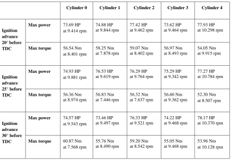
Table 2 presents the results of the investigation of internal combustion engines with all tested
cylinders for different values of ignition advance angles. Ignition timing, in a spark ignition
internal combustion engine, is the process of setting the ignition advance angle relative to the
piston position. The correct ignition advance angle is important for the performance of an IC
engine. This angle affects fuel economy and engine power.
Table 2. Maximum power and maximum torque for internal combustion engines with tested
cylinders
Cylinder 0 Cylinder 1 Cylinder 2 Cylinder 3 Cylinder 4
Ignition advance 20°before TDC
Max power 73.69 HP
at 9.414 rpm
74.88 HP at 9.844 rpm
77.42 HP at 9.462 rpm
73.62 HP at 9.464 rpm
77.93 HP at 10.298 rpm
Max torque 56.54 Nm
at 8.401 rpm
58.25 Nm at 7.878 rpm
59.07 Nm at 8.402 rpm
56.97 Nm at 8.493 rpm
54.05 Nm at 9.915 rpm
Ignition advance 25° before TDC
Max power 74.93 HP
at 9.881 rpm
76.53 HP at 9.619 rpm
76.29 HP at 9.764 rpm
75.29 HP at 9.342 rpm
77.27 HP at 10.784 rpm
Max torque 56.36 Nm
at 8.974 rpm
56.83 Nm at 7.446 rpm
56.32 Nm at 7.637 rpm
56.60 Nm at 9.362 rpm
52.30 Nm at 8.507 rpm
Ignition advance 30° before TDC
Max power 74.57 HP
at 9.543 rpm
73.46 HP at 9.497 rpm
76.33 HP at 9.521 rpm
74.22 HP at 9.468 rpm
78.17 HP at 10.370 rpm
Max torque 60.87 Nm
at 7.568 rpm
55.76 Nm at 8.490 rpm
59.20 Nm at 8.542 rpm
55.05 Nm at 9.468 rpm
[image:12.595.74.526.427.741.2]It was observed that the second variant (2) of surface texturing without DLC coating was
characterised by a high increase of power. For an ignition advance angle of 20°, this power
increased by 3.74 brake horse power (HP), which is 5.1% of the power of the engine with the
conventional cylinder. For the ignition advance angles of 25° and 30°, the relative increases
were 1.8 and 2.4% respectively. This is a substantial change for high-performance engines.
Textured cylinder 1 yielded smaller changes in engine characteristics. For the ignition advance
angles of 20° and 25°, increases in maximum power ranged between 1.6% and 2.1%
respectively. In the last measurement (ignition advance 30° before TDC) for this cylinder,
power decreased by 1.5%. When engine with cylinder 3 was tested, no substantial changes of
maximum power in relation to the conventional variant were observed, and a small decrease in
the maximum power occurred. In this case, however, a high decrease (up to 16%) in torque for
low rotational speeds was observed due to cylinder surface texturing for the middle and highest
ignition advance angles. During lubrication of the piston – piston ring–cylinder assembly – with
oil, an unprofitable situation may emerge when dimples are not completely filled with lubricant
and where the hydrodynamic lubrication effect is limited. For textured surfaces, it is necessary
to adjust the additional oil capacity to the amount of lubricant supplied by the lubrication system
to the friction zone [32]. A distinct decrease in torque in the engine with cylinder 3, which has
the highest density of dimples for low rotational speeds, is an example of the engine’s reaction
when a limited amount of lubricant is present.
The largest increase in maximum power was found in the engine using a DLC-coated textured
cylinder compared to the engine with cylinder 0. Similar to engines with other textured
cylinders, for the ignition advance angle of 20°, this increase was the highest: 4.24 HP (5.8%).
For the ignition advance angles of 25° and 30°, the relative increases of maximum power were
3.1 and 4.8% respectively. For this engine, the maximum power from all analysed engines was
obtained for the highest rotational speeds.
An increase of power as a result of cylinder surface texturing was related to changes in torque
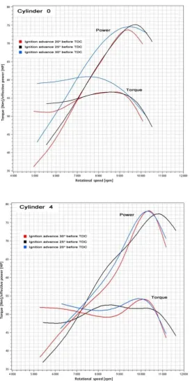
runs. The torque curves were flattened in a wide range of rotational speeds of the engine. Figure
Figure 3. Torque and power as a function of the rotational speed of the test engine when equipped with cylinders 0 and 4
One can see from the analysis of Figure 3 that the engine with cylinder 4 generated more power
at a distinctly higher rotational speed compared to the engine with untextured cylinder 0. The
[image:14.595.81.355.90.638.2]1,000 rpm. This allows the powering of the motorbike with higher maximum speed. The values
for torque rate were lowered smoothly, but the torque curves became more stable, especially
near the upper speed limits. This would provide better vehicle dynamics at high driving speeds.
Additionally, the engine with cylinder 4 showed that output parameters were less responsive to
engine-tuning imperfections in terms of ignition advance angle sets.
In this work, the combined effect of surface texturing and DLC coating on the functional
properties of high-performance engines used in speedway competition motorcycles has been
studied. The obtained findings can be used in other internal combustion engines, and in
particular competitions engines. For commercial applications, exhaust emissions should be
taken into consideration.
3.2. Post-engine test surface characterisation
Figure 4 presents the contour plots and texture directions of cylinders 1 and 4 after the operation
of internal combustion engines between 15–25 heats. As a result of wear, the surface
topography of the cylinders has changed. For untextured surfaces after honing, surface height
decreased with the creation of a new direction along the movement direction of the piston rings.
A similar situation occurred for the surface topographies of textured cylinders. Surface
amplitude decreased and a reduction in the depth of cavities occurred. A new direction, parallel
to the piston–ring movement, was formed. The creation of this direction is related with a
decrease in the texture–aspect ratio Str and an increase in the peak density Spd. Definitions of
surface topography parameters from the ISO standard 25178 are given in Reference [33]. The
Str parameter characterises the isotropy of the surface. If Str is close to 1, then the surface has
the same properties regardless of direction, which means it is isotropic. Anisotropic surfaces
with a dominant texture direction have Str parameters close to 0. The peak density is computed
by dividing the number of peaks by unit area. This can be used in applications where contact is
involved. Surface height was assessed by the Sq and Sz parameters. The Sq parameter is defined
as the root mean-square value of the surface deviations within the sampling area. The Sz
parameter is the sum of the largest peak height value and the largest valley depth value.
Surface change in cylinder 1 was smaller than that of cylinder 4. Since mileages were not the
same, the analysis of the change of surface topographies was only quantitative. Dimple depth
from cylinder 1 (Figure 2a and Figure 4a) changed from 5 µm to 3.5 µm on average. The root
0.56 µm and from 5.9–6.1 µm to 4.3–4.7 µm respectively. Due to wear, a new direction, parallel
to the direction of the piston ring movement (third direction – see Figure 4c), was created. As
a result, the texture–aspect ratio Str decreased from 0.7–0.75 to 0.61–0.54, and peak density
increased from 550–650 1/mm2 to 850–1,300 1/mm2.
a b
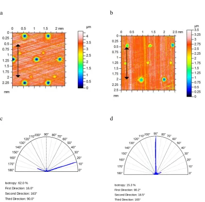
[image:16.595.76.499.201.615.2]c d
Figure 4. Contour plots (a, b) and main surface directions (c, d) of cylinders 1 (a, c) and 4 (b, d) after engine operation
The depth of dimples from cylinder 4 (Figure 2b and Figure 4b) decreased to 2–2.5 µm. Due to
wear, the Sq and Sz parameters changed from 0.48–0.55 µm to 0.32–0.36 µm, and
5.3-5.6 µm to 3.2–3.4 µm respectively. As the wear was severe (the shallow honing valleys
were erased), a new direction, which became the main direction, was formed (first direction –
see Figure 4d). Due to the creation of this direction, the Str parameter decreased from 0.4–0.5
0° 10° 20° 30° 40° 50° 60° 70° 80° 90° 100° 110° 120° 130° 140° 150° 160° 170° 180°
Isotropy: 62.0 % First Direction: 16.0° Second Direction: 163° Third Direction: 90.0°
0° 10° 20° 30° 40° 50° 60° 70° 80° 90° 100° 110° 120° 130° 140° 150° 160° 170° 180°
to 0.15–0.2, and the Spd parameter increased from 110–150 1/mm2 to 550–600 1/mm2. Cracks
were not formed on the cylinder surface with deposited DLC coating. A similar tendency of
parameter changes was also found to be the case for the other cylinders.
4. Conclusions
Dimples were successfully created on cylinder surfaces with Nikasil coating using the plastic
deformation. One cylinder was subjected to deposition of DLC coating and then surface
texturing. The results of the functional performance of high-performance internal combustion
engines with textured and untextured cylinder surfaces were compared. It was found that
cylinder texturing typically led to a decrease in resistance to sliding movement following an
increase in the amount of lubricants in dimples. A decrease in the coefficient of friction caused
an increase of power in a wide range of rotational speeds. It also led to a shift of engine
characteristics towards higher rotational speeds.
The increase of power was the largest for the textured cylinder with a deposition of DLC
coating. In this case, the increase of brake power values reached up to 4.8 HP (5.8%), while the
increase in the rotational speed was about 1000 rpm as compared to the untextured bore. This
allows powering the vehicle (motorbike) with a higher maximum speed, which would also
provide better vehicle dynamics at high driving speeds. Good operational properties were also
obtained for textured cylinders without DLC coating for the highest and medium dimples
density.
For textured cylinders after engine operation, surface height decreased and a reduction in the
depth of dimples was observed. A new direction, parallel to the piston ring movement was
formed. The creation of this new direction is related to a decrease in the texture–aspect ratio Str
and an increase of peak density Spd.
References
1. Holmberg K, Andersson P, Erdemir, A. Global energy consumption due to friction in passenger cars, Tribology International 47 (2012) 221-234
3. Zhou Y, Zhu H, Tang W, Ma C, Zhang W. Development of the theoretical model for the optimal design of surface texturing on cylinder liner, Tribology International 52 (2012) 1– 6,
4. Hua X, Sun J, Zhang P, Ge H, Fu Y, Ji J, Yin B. Research on discriminating partition laser surface micro-texturing technology of engine cylinder, Tribology International 98 (2016)190–196
5. Biboulet N, Lubrecht AA. Analytical solution for textured piston ring – cylinder liner contacts (1D analysis), Tribology International 96 (2016) 269–278
6. Tang W, Zhou Y, Zhu H, Yang H. The effect of surface texturing on reducing the friction and wear of steel under lubricated sliding contact, Applied Surface Science 273 (2013) 199–204
7. Yin B, Li X, Fu Y, Yun W. Effect of laser textured dimples on the lubrication performance of cylinder liner in diesel engine, Lubrication Science 24 (2012) 293–312
8. Usman A, Park CW. Optimizing the tribological performance of textured piston ring–liner contact for reduced frictional losses in SI engine: Warm operating conditions, Tribology International 99 (2016) 224–236
9. Vl descu S-C, Medina S, Olver AV, Pegg IG, Reddyhoff T. Lubricant film thickness and friction force measurements in a laser surface textured reciprocating line contact simulating the piston ring–liner pairing, Tribology International 98 (2016) 317–329
10. Grabon W, Koszela W, Pawlus P, Ochwat S. Improving tribological performance of piston ring – cylinder liner frictional pair by liner surface texturing, Tribology International 61 (2013)102-108
11. Checo HM, Ausas RF, Jai M, Cadalen J-P, Choukroun F, Buscaglia G-C. Moving textures: Simulation of a ring sliding on a textured liner, Tribology International 72 (2014) 131–142 12. Koszela W, Galda L, Dzierwa A, Pawlus P. The effect of surface texturing on seizure
resistance of a steel-bronze assembly, Tribology International 43 (2010) 1933-1942 13. Koszela W, Pawlus P, Rejwer E, Ochwat S. Possibilities of oil pockets creation by the
burnishing technique, Archives of Civil and Mechanical Engineering 13 (2013) 465-471 14. Koszela W, Dzierwa A, Galda L, Pawlus P. Experimental investigation of oil pockets effect
on abrasive wear resistance, Tribology International 46 (2012) 145-153
15. Johansson S, Nilsson PH, Ohlsson R, Anderberg C, Rosen B-G. New cylinder liner surfaces for low oil consumption, Tribology International 41 (2008) 854-859
16. Mezghani S, Demirci I, Yousfi M, El Mansori M. Mutual influence of crosshatch angle and superficial roughness of honed surfaces on friction in ring-pack tribo-system, Tribology International 66 (2013) 54–59
17. Tomanik E, El Mansori M, Souza R, Profito F. Effect of waviness and roughness on cylinder liner friction, Tribology International 120 (2018) 547-555
18. Dimkovski Z, Tomanik E, Profito F. Influence of measurement and filtering type on friction predictions between cylinder liner and oil control ring, Tribology International 100 (2016)7-17
19. Wos S, Koszela W, Pawlus P, Drabik J, Rogos E. Effects of surface texturing and kind of lubricant on the coefficient of friction at ambient and elevated temperatures, Tribology International 117 (2018) 174-179
20. Wos S, Koszela W, Pawlus P. The effect of both surfaces textured on improvement of tribological properties of sliding elements, Tribology International 113 (2017) 182-188 21. Gachot C,Rosenkranz A, Hsu SM, Costa HL. A critical assessment of surface texturing for
friction and wear improvement, Wear 372–373 (2017) 21–41
23. Podgornik B, Jacobson S, Hogmark S. DLC coating of boundary lubricated components— advantages of coating one of the contact surfaces rather than both or none, Tribology International 36 (2003) 843-849
24. Mobarak HM, Masjuki HH, Mohamad EN, Rahman SMA, Al Mahmud KAH, Habibullah M, Salauddin S. Effect of DLC coating on tribological behavior of cylinder liner piston ring material combination when lubricated with Jatropha oil, Procedia Engineering 90 (2014) 733 – 739
25. Tung SC, Gao H. Tribological characteristics and surface interaction between piston ring coatings and a blend of energy-conserving oils and ethanol fuels, Wear 255 (2003) 1276-1285
26. Podgornik B, Hren D, Viˇzintin J, Jacobson S, Stavlid N, Hogmark S. Combination of DLC coatings and EP additives for improved tribological behaviour of boundary lubricated surfaces Wear 261 (2006) 32–40
27. Cho D-H, Lee Y-Z, Evaluation of ring surfaces with several coatings for friction, wear and scuffing life, Transactions of the Nonferrous Metals Society of China 19 (2009) 992-996 28. Rejowski E, Mordente S, Pillis M, Casserly T. Application of DLC coating in cylinder
liners for friction reduction, SAE Technical Paper 2012-01-1329 (2012) 29. J, Goodman, Nikasil and Alusil. Engine Professional (2008) 18-22
30. Speedway FAQ: Main rules http://www.speedway-faq.org/mainrule.html last visited 1st May 2018
31. W, Koszela, Polish Patent No, 217855 (2014), Head for oil pockets creation on cylinder liner surface
32. Wos S, Koszela W, Pawlus P. Determination of oil demand for textured surfaces under conformal contact conditions. Tribology International 93 (2016) 602-613