Theses Thesis/Dissertation Collections
2010
Interactive natural user interfaces
Sean Patrick Janis
Follow this and additional works at:http://scholarworks.rit.edu/theses
This Thesis is brought to you for free and open access by the Thesis/Dissertation Collections at RIT Scholar Works. It has been accepted for inclusion in Theses by an authorized administrator of RIT Scholar Works. For more information, please [email protected].
Recommended Citation
by
Sean Patrick Janis
A Thesis Submitted in Partial Fulfillment of the Requirements for the Degree of Master of Science
in Computer Science
Supervised by
Assistant Professor Dr. Reynold Bailey Department of Computer Science
B. Thomas Golisano College of Information Science Rochester Institute of Technology
Rochester, New York May 2010
Approved by:
Dr. Reynold Bailey, Assistant Professor
Thesis Advisor, Department of Computer Science
Dr. Hans-Peter Bischof, Associate Professor
Committee Member, Department of Computer Science
Dr. Joseph Geigel, Associate Professor
Rochester Institute of Technology
B. Thomas Golisano College of Information Science
Title:
Interactive Natural User Interfaces
I, Sean Patrick Janis, hereby grant permission to the Wallace Memorial Library to re-produce my thesis in whole or part.
Sean Patrick Janis
Dedication
This thesis is dedicated to my mother and father for their persistent love and support
which continually enables me to follow my dreams.
”If you can dream it, you can do it.”
Acknowledgments
This Masters Thesis would have not been possible without the knowledge and support of
my various advisors and colleagues.
First and foremost, I would like to thank my Masters Thesis advisors for guiding me
through this incredible adventure. Thanks to Professor Bailey for allowing me to try
some-thing radically new and different; Professor Bischof for teaching me the art of giving a
great presentation and challenging me to continually improve my work; Professor Geigel
for making learning about Computer Animation, Computer Graphics and Virtual Reality
the most fun, interesting experience I have ever studied.
Next, I would like to thank my professional colleagues who have provided countless
support which lead to my project’s success. Thanks to Jeff Hanzlik for teaching me the
basics to soldering an infrared LED circuit; Kevin Peters, Mike Janis (my dad) and my Mike
Janis, Jr. (my brother) for helping build a prototype fog screen water tank. Barry Nobles
for helping develop concave mirror prototypes for my holographic display component; Joe
Presicci for giving me advice about infrared tracking problems; Mike Doser for being a
great mentor and inspiring me to explore various mad scientist projects; Adam Kent for
teaching me about basic circuit design and components; Dave Garrison, Bob Post, Dave
Garigen and Paul Voglewede for offering a lending ear for my various ideas.
Finally, in Winter 2007, I remember walking into RIT’s Computer Science office
look-ing to apply to graduate school. At the time, I was very excited to start the program and
advance my skill set. On that day, I remember a very wise graduate advisor giving me the
best academic advice I had received up to that point. ”Most students that work full-time
and attend graduate school part-time do very well taking one class per quarter. Take your
time and enjoy the graduate program.” Thank you again, Professor Bischof for the excellent
Abstract
For many years, science fiction entertainment has showcased holographic technology and
futuristic user interfaces that have stimulated the world’s imagination. Movies such asStar
WarsandMinority Reportportray characters interacting with free-floating 3D displays and
manipulating virtual objects as though they were tangible. While these futuristic concepts
are intriguing, its difficult to locate a commercial, interactive holographic video solution
in an everyday electronics store. As used in this work, it should be noted that the term
holography refers to artificially created, free-floating objects whereas the traditional term
refers to the recording and reconstruction of 3D image data from 2D mediums.
This research addresses the need for a feasible technological solution that allows users
to work with projected, interactive and touch-sensitive 3D virtual environments. This
re-search will aim to construct an interactive holographic user interface system by
consolidat-ing existconsolidat-ing commodity hardware and interaction algorithms. In addition, this work studies
the best design practices for human-centric factors related to 3D user interfaces.
The problem of 3D user interfaces has been well-researched. When portrayed in
sci-ence fiction, futuristic user interfaces usually consist of a holographic display, interaction
controls and feedback mechanisms. In reality, holographic displays are usually represented
by volumetric or multi-parallax technology. In this work, a novel holographic display is
presented which leverages a mini-projector to produce a free-floating image onto a fog-like
surface. The holographic user interface system will consist of a display component: to
project a free-floating image; a tracking component: to allow the user to interact with the
3D display via gestures; and a software component: which drives the complete hardware
system.
After examining this research, readers will be well-informed on how to build an
Contents
Dedication. . . iii
Acknowledgments . . . iv
Abstract . . . v
1 Introduction. . . 1
1.1 Problem Introduction . . . 1
1.1.1 Introduction . . . 1
1.1.2 Background and Definitions . . . 2
1.1.3 Description . . . 4
1.2 System Components . . . 4
1.2.1 Holographic Display . . . 6
1.2.2 User Tracking and Control . . . 6
1.2.3 Software Framework . . . 8
2 Related Work . . . 10
2.1 Musion Eyeliner Holographic Projection System . . . 10
2.2 Dreamoc 3D Holographic Display . . . 11
2.3 Provision 3D Media . . . 11
2.4 Heliodisplay . . . 12
2.5 FogScreen . . . 13
2.6 Volumetric Finger Tracking . . . 14
2.7 Wiimote Infrared Finger Tracking . . . 15
2.8 Ultrasound Radiation Technology . . . 16
3 Interactive 3D User Interfaces . . . 17
3.1 Need for 3D User Interfaces . . . 17
3.1.1 Technological Advancements . . . 17
3.1.2 Comparing Traditional Users Interfaces . . . 18
3.2 Human-Centered Design . . . 20
3.2.1 Basic Overview . . . 20
3.2.2 Application to our System . . . 22
3.3 Crafting a Good User Interface . . . 23
3.3.1 Choosing the Right Equipment . . . 23
3.3.2 Developing Appropriate Interactions . . . 24
3.3.3 Presentation . . . 25
3.4 Summary . . . 27
4 Holovee: A Social Networking Application . . . 29
4.1 System Design . . . 29
4.1.1 Basic Overview . . . 29
4.1.2 Design Diagrams . . . 31
4.2 Programming the Framework . . . 35
4.2.1 Choosing a Development Environment . . . 35
4.2.2 Working with the Facebook API . . . 37
4.2.3 Working with the Wiimote Tracking Library . . . 40
4.2.4 2D Visuals on 3D Controls . . . 40
4.3 Application Usage . . . 42
4.3.1 First-Time Use . . . 42
4.3.2 Tasks and Navigation via Speech Commands . . . 43
4.3.3 Manipulating 3D Controls . . . 47
4.4 Other Software Approaches . . . 49
4.4.1 XNA Game Framework . . . 49
4.5 Summary . . . 51
5 User Tracking and Input Devices . . . 53
5.1 Input Devices . . . 53
5.2 Tracking Mechanisms . . . 53
5.2.1 Infrared LED Tracking . . . 53
5.2.2 Markerless Tracking . . . 56
5.2.3 Voice Commands and Speech Tracking . . . 57
5.3 Gesture Recognition Formulas . . . 59
5.3.1 Basic Algorithms . . . 59
5.4 Tracking Design . . . 61
5.4.1 Infrared LED Circuit Design . . . 61
5.4.3 Wiimote Hardware and Interface . . . 64
5.4.4 Other Available Hardware Options . . . 65
5.5 Summary . . . 65
6 3D Displays . . . 67
6.1 Basic Optics . . . 67
6.1.1 Eye Perception . . . 67
6.1.2 Light Travel . . . 68
6.1.3 Visual Depth Cues . . . 69
6.2 3D Display Types . . . 70
6.2.1 Volumetric Displays . . . 70
6.2.2 Parallax Displays . . . 73
6.3 3D Stereoscopy . . . 75
6.3.1 Passive Red-Blue Anaglyphs . . . 75
6.3.2 Passive Polarization . . . 76
6.3.3 Active Shutter . . . 78
6.4 System Display . . . 79
6.4.1 Ultrasonic Water Fogger . . . 79
6.4.2 Slim Air Fan Flow . . . 80
6.4.3 Custom Water Tank . . . 81
6.4.4 Projector and Mirror Positioning . . . 83
6.4.5 Holovee’s Final Holographic Display . . . 85
6.5 Summary . . . 85
7 Results. . . 93
7.1 Results . . . 93
7.1.1 Hardware Availability . . . 93
7.1.2 Believability . . . 94
7.1.3 Practicality . . . 94
7.2 Future Work . . . 95
7.2.1 Haptic Feedback . . . 95
7.2.2 3D Stereoscopic Image Viewing . . . 96
7.2.3 Discrete Pixel 3D Holographic Display . . . 96
7.3 Conclusion and Lessons Learned . . . 97
List of Tables
3.1 Hardware Component Needs . . . 24
4.1 Software Class Diagram Definitions . . . 35
4.2 Available Speech Commands . . . 46
List of Figures
1.1 System Component Overview . . . 5
1.2 Transparent Fog Screen . . . 7
1.3 Tracking Gloves equipped with Infrared LED diodes . . . 8
1.4 Holovee - Social Networking Management Application . . . 9
3.1 IDEO’s Human-Center Designed Process viewed through a series lenses [20]. 21 3.2 Holovee Help Tutorial for Hand Gesture Interactions . . . 26
4.1 Holovee Main Screen . . . 30
4.2 Basic Application Structure . . . 31
4.3 User Photos Page Structure . . . 32
4.4 Friend Status Page Structure . . . 33
4.5 2D Image Visual mapped onto a 3D Object . . . 41
4.6 Facebook Friend Status Tile . . . 43
4.7 Facebook Photo Tile . . . 44
4.8 Adding Captions to Facebook Photo Tiles . . . 46
4.9 Adding Tags to Facebook Photo Tiles . . . 47
4.10 Simple 3D Tile Selection and Translation . . . 48
4.11 3D Tile Scaling . . . 49
4.12 3D Tile Rotation . . . 50
5.1 The Electromagnetic Spectrum - Infrared Light is invisble to the human eye [13] . . . 54
5.2 Wii Video Game Tracking System [39] . . . 55
5.3 Markerless Figure Representation [55] . . . 57
5.4 Speech Recognition Processing Engine [36] . . . 59
5.5 Infrared LED Circuit Design: A minimum 6.8 ohms resistor is required [2]. 63 5.6 The completed Infrared LED Circuit: Assembled with two Infrared LEDs, a 10 ohm resistor, a watch battery and a simple switch. . . 63
5.7 Infrared LEDs mounted on User Gloves . . . 64
6.2 3D Volumetric Display [24] . . . 71
6.3 Refraction Properties via Snell’s Law [56] . . . 72
6.4 Pepper’s Ghost effect using Traditional Optics effects [50] . . . 73
6.5 Futuristic Parallax Discrete Pixel Display [17] . . . 74
6.6 Traditional 3D Anaglyph . . . 76
6.7 Polarization Display filtering Unpolarized Light [8] . . . 77
6.8 12-Jet Ultrasonic Water Fogger . . . 80
6.9 Honeywell Tower Air Fan . . . 81
6.10 Initial Projection with Ultrasonic Fogger and Honeywell Tower Air Fan . . 82
6.11 Custom Water Tank Air Intake Opening . . . 83
6.12 Custom Water Tank Side Profile . . . 84
6.13 Custom Water Tank with Fan . . . 84
6.14 Custom Water Tank Design . . . 87
6.15 The 3M MPro120 Micro Projector aimed at the Mirror positioned behind our Fog Screen Display . . . 88
6.16 Complete System Setup . . . 89
6.17 Using an Acrylic Rear Projection Sheet to Position our Projector . . . 90
Chapter 1
Introduction
1.1
Problem Introduction
1.1.1 Introduction
Every year, our living rooms become invaded with more and more cutting edge technology
that facilitates our lives. Science fiction entertainment often portrays computing
technol-ogy light years ahead of its actual capabilities. This research addresses the need for a
feasible technological solution that allows users to work with projected, interactive and
touch-sensitive 3D virtual environments. More specifically, this work explores why
holo-graphic user interfaces systems are not often readily available. We aim to research, design
and build an interactive holographic user interface system that can be applicable to
numer-ous graphics arenas. The end system will be evaluated by the degree to which it satisfies
the below categories:
• Hardware Availability - The system shall make use of current state-of-the-art
holo-graphic displays, interaction tracking and touch feedback.
• Believability - The system shall take into account valuable human-computer
interac-tion factors and be ergonomically friendly.
• Practicality - The system shall be applicable to one or more of the following areas
including augmented reality, video games, advertisements, entertainment or futuristic
Holographic user interfaces provide a certain excitement to people. When first seeing
a free-floating, 3D image, people are mystified by this futuristic technology. Not only can
these futuristic interfaces astound people, but they also have very practical applications.
There are numerous arenas where interactive holographic user interface systems can be
applied such as augmented reality, video games, medical procedures and advertisements.
Providing medical students with a 3D volumetric view of patient’s brain can allow them
to better understand details hidden in flat 2D images. Interactive holographic surfaces
could allow video gamers to fight a projected 10-foot dragon in their living room without
the need for a television. Bringing 360-degree product views to households could better
educate online shoppers about merchandise features before final purchases. With futuristic
user interfaces, the components to create an interactive holographic display exist and can
be combined to develop an intuitive, eye-catching system.
This work’s main objective is to educate the reader about interactive holographic user
interfaces and also provide insight into how to build a feasible system from existing
com-modity hardware. We hope this work will excite readers about futuristic user interfaces and
allow them to realize that this once advanced technology is more realizable than expected.
1.1.2 Background and Definitions
At a basic level, we need to create a solution that simulates a realistic environment. The
realistic environment should exhibit native, intuitive sensory cues. As discussed by [17],
physical movement is the strongest cue for distinguishing object depth. Hence, seeing
an accurate projected image is critical to system believability. Moreover, intuitive hand
gestures adapted from science fiction entertainment and control object placement should
be considered. Most often, learning the user interface controls we observe in movies and
television feel more natural because they are engrained in our semantic or context-based
memory. Grasping or touching virtual system objects should provide similar reactionary,
feedback traits as exhibited in real life. As detailed by [19], presenting users with a
stim-ulator such as haptic feedback technology, depresses the user’s focus from the holographic
more consumed with the actual interface.
In this work, a holographic display is defined as a presentation surface that creates the
illusion of free-floating 3D images. That is to say, given a graphics software package that
renders perspective scenes, our holographic display will project a 3D scene representation
in free space. Similar to a 2D display model, the holographic display surface will
dynam-ically update as the graphics software data model changes. Previous authors such as [16]
and [24], used enclosed volumetric, rotating mirrors for their holographic projections. Our
holographic display will not contain any moving parts. These displays will be discussed in
upcoming sections.
Interaction components are defined as the set of controls that allow users to interface
with the holographic display. As the holographic display projects a free-floating image,
users will use interaction components such as infrared tracking gloves and hand gestures
to control objects within the the artificial 3D environment. Infrared tracking technology is
often used for determining a user’s location relative to the display. For example, Nintendo’s
Wii gaming system uses an infrared remote control and a reflective infrared light source to
track a user’s movement. Combining infrared tracking with custom gesture recognition,
our holographic user interface can offer intuitive interactions such as pinching and hand
sliding to manipulate system objects.
Feedback mechanisms are defined as visual, audio and touch sensation cues that are
applied to the user as a result of interface interactions. Visual cues are the most basic
resulting feedback mechanism and occur when the user augments an interface item. For
example, if the user pushes a ball, the ball will move similar to real life. For an audio cue,
the user may decide to bounce the ball with a simple hand gesture that causes an appropriate
sound to play. Moreover, haptic technology is an important feedback mechanism because
users need to believe the objects they touch are realistic. Haptic technology is defined as
taking advantage of a user’s sense of touch by applying forces, vibrations and motions upon
the user. For a holographic user interface, developing a haptic component is the toughest
system aspect as free-floating images are not tangible assets. In this work, we leave the
Finally, a software framework is defined as the application level source code which
drives our system’s hardware components. In our system, we will be creating a free-floating
image illusion with which the user can interact. We will need to create an intuitive user
interface which allows users to observe and evaluate the benefits of a holographic user
interface; hence, we present Holovee, a simple social networking management system.
Our social networking application will be based on Facebook’s Application Programming
Interface (API). Facebook is a popular online social networking website which connects
millions of worldwide users. In our application, users will be able to view and manipulate
their Facebook data with intuitive speech commands and hand gestures.
1.1.3 Description
With a basic description of system components, we can begin to visualize how our system
will be constructed. Again, we are looking to build a holographic system that satisfies
a growing need for more dynamic, visual user interfaces. As will be discussed, recent
researchers such as [24] and [18] have made significant advances in display, interaction
and feedback technology. This research will serve as a solid foundation for our work as
each component will contribute to the larger system.
While the concept of interactive holographic user interfaces is very intriguing, even a
highly futuristic system would be useless without any ergonomic considerations. There has
been a plethora of work related to human-computer interactions with 3D user interfaces.
Specifically, the authors in [6] have consolidated a rather extensive compilation of 3D user
interface theory and practices. A distinguishing factor between our work and past work
will be our emphasis and application of these best 3D user interface design practices into
our system.
1.2
System Components
As discussed, our holographic user interface system will consist of a holographic display,
how our system components interact to become operational. The following section briefly
details the hardware used for each system component. Future sections will discuss each
[image:18.612.108.513.160.593.2]hardware component’s technical specifications in more detail.
1.2.1 Holographic Display
Our holographic display will use simple effects to create the illusion of free-floating images.
These basic effects will be discussed in future sections, but are relatively easy to implement.
The holographic display’s hardware components include a 3M MPro120 micro projector,
an ultrasonic water fogger and a commercial slim air fan to direct the produced fog. For
our work, the fog-like mist will serve as a transparent display surface to project onto.
A projector is commonly used to project a digital signal from a personal computer or
video source onto a reflective screen. Our system leverages a projector to project our
com-puter’s video output onto a custom display surface. Most often, static holographic display
systems such as [48] and [53] use custom mirror arrangements to reflect and manipulate
light in desired directions. In addition, the creators of [53] use a high intensity LCD screen
to reflect into their lens system. We chose 3M’s MPro120 micro projector because of its
size and commercial availability. Instead of using an LCD screen and placing our system
computer directly into our lens system, using an external projector allows easy access to
the system computer and is flexible enough for larger scale setups. When operational, the
slim air fan will vacuum the fog and direct it vertically to produce a steady, transparent fog
screen.
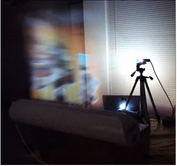
Because our system uses a transparent water fog screen as its projection surface, room
lighting and a water source are two important setup considerations. Our holographic
dis-play creates the illusion of a free-floating image without the need for complex lenses and
mirrors. As exhibited in [53], concave mirror holographic display setups often require users
to be at specific viewing locations. Because our system is not using a lens-mirror setup,
we can be less concerned with problematic user viewing angle issues. Figure 1.2 shows a
basic picture of our system’s design.
1.2.2 User Tracking and Control
Infrared cameras are often used to track infrared light emitting diodes. Invisible to the
hu-man eye, infrared light receivers are common in remote controls and home entertainment
Figure 1.2: Transparent Fog Screen
interact with our software interface. With this in mind, we use the Nintendo Wiimote as
our infrared tracking mechanism because of its widespread availability, low cost and
soft-ware development kit. The Nintendo Wiimote is a hardsoft-ware device that uses an integrated
infrared camera to track a stationary infrared emitting light sensor bar. The controller
de-vice pairs with Nintendo Wii video game consoles and allows players to interact with video
games.
Our system inverts the standard use for a Nintendo Wiimote. Instead of a moving
Wi-imote tracking a stationary sensor bar, we keep the controller stationary and track moving
infrared lights mounted to the user’s hands. This method is simpler and less bulky than
mounting a full-featured infrared camera onto our users’ hands. To give granular control
of our holographic interface, we present interactive, user wearable gloves equipped with
by university researcher Johnny Lee [29]. The infrared lights are mounted to the wearable
gloves and are powered by 3-volt watch batteries. When powered on, the diodes emit an
infrared light which is invisible to the human eye, yet recognizable by the Nintendo
Wi-imote. For better tracking performance, we cluster multiple infrared LEDs together. The
[image:21.612.202.418.198.470.2]infrared tracking gloves are pictured in Figure 1.3.
Figure 1.3: Tracking Gloves equipped with Infrared LED diodes
1.2.3 Software Framework
Our software framework is the driving force behind our system’s operation. The software
framework was written in the C# programming language and uses Windows Presentation
Foundation (WPF) as its graphical subsystem to interact with our computer’s rendering
hardware. We use Microsoft’s Visual Studio 2008 as our development and debugging
technologies and because they allow us to rapidly prototype high quality graphical
Win-dows applications. Moreover, the WPF application programming interface allows
develop-ers to easily manipulate graphical objects and has an abundance of good coding samples.
Having great programming resources allow developers to work both efficiently and reduce
[image:22.612.115.506.195.431.2]unnecessary code. Figure 1.4 shows a screenshot of our social networking application.
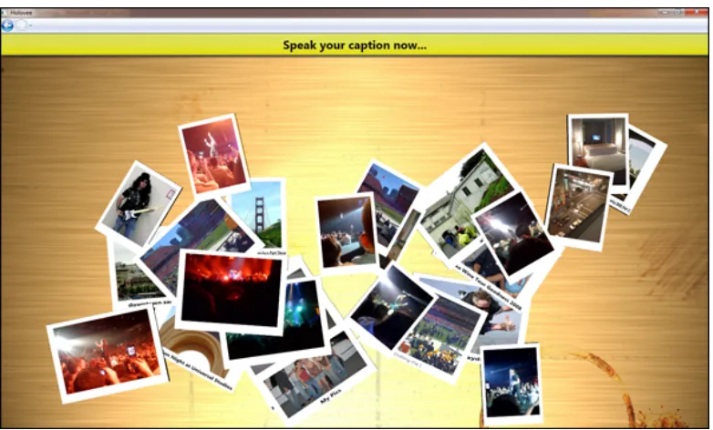
Figure 1.4: Holovee - Social Networking Management Application
As aforementioned, our system’s main graphical component will be Holovee, the social
networking management application. Holovee presents users with their uploaded Facebook
photos, friend information and status data. We present the user with speech commands to
easily manipulate their data. The software framework also encapsulates a tracking
com-ponent which manages the computer’s interactions with the Nintendo Wiimote. During
runtime, the software framework will read the Wiimote’s infrared tracking samples and
translate them to user interface actions. For example, if the tracking component detects
two points moving closer together, it may consider this a user selection or pinching
indi-cation. More detail will be provided in future sections about the available custom gestures
Chapter 2
Related Work
2.1
Musion Eyeliner Holographic Projection System
In the search for futuristic display technology, Dimensional Studios Ltd., a London-based
company, developed Musion Eyeliner, a commercially available 3D holographic video
pro-jection system [32]. At a basic level, the Musion Eyeliner system consists of an overhead
projector, a reflective screen and custom transparent foil. When running, the overhead
projector projects a high definition video feed onto the reflective display screen which is
positioned on the ground floor. The display screen then reflects the image onto a 45-degree
angled piece of transparent foil. From an audience’s perspective, the reflected image on
the transparent foil creates the illusion of artificial images being dynamically inserted into
a real world scene.
The Musion Eyeliner system’s artificial illusion is often known as Pepper’s Ghost effect.
In 1862, John Henry Pepper, a university lecturer, created an illusion which provided
audi-ences with phantomly appearing and disappearing images [17]. Since the 19th century was
not plentiful with electronic projectors and reflective screens, Pepper used an angled sheet
of glass to reflect a hidden stage. Images were made visible by lighting the hidden stage,
thereby reflecting the hidden stage object through the glass and producing a free-floating
image illusion.
We experimented with the Pepper’s Ghost phenomenon and felt it wasn’t practical for
our application. Because the Musion Eyeliner system and Pepper’s Ghost effect are not
addition, Musion Eyeliner’s system works very well because audiences are usually
posi-tioned farther from the display unit. Hence, the effect is more believable and the user is not
concerned with interacting with the display.
2.2
Dreamoc 3D Holographic Display
Similar to the Musion Eyeliner Holographic Projection System, RealFiction, a
Copenhagen-based company, has developed Dreamoc, a 180-degree virtual projection system [48].
Al-though unpublished, the system appears to use a top-down version of Pepper’s Ghost effect
to project images onto a transparent surface which creates a free-floating illusion. Whereas
the Musion Eyeliner Holographic Display system’s reflected image is projected upward,
the Dreamoc system’s reflected image is projected downward; hence, creating a reverse
volumetric pyramid sensation. When the Dreamoc system creates a free-floating image,
users are able to place real objects into the system’s projection space to simulate visually
stunning, complementary effects. The Dreamoc holographic display’s base dimensions are
45-inches wide by 24-inches high.
The Dreamoc’s semi-enclosed surface design lends itself well to our application. By
creating an enclosure which has a top cover and back surface, we can better integrate our
micro projector and infrared tracking mechanism and obstruct them from the user’s view.
By doing so, the user will feel more engrained into the system’s experience. However,
because the Dreamoc system uses an enclosed surface, our projection space is now limited
to the structure’s volume. Therefore, we will experiment with both enclosed and
non-enclosed holographic display designs to determine which proves most beneficial.
2.3
Provision 3D Media
Provision Interactive Technologies, Inc., an interactive display company, offers many
va-rieties of 3D holographic displays which provide the illusion of free-floating images [53].
Targeted more towards in-store media and advertisements, Provision provides next-generation
few details as to their 3D displays inner workings. A further search for their display’s
technical specifications can lead to Provision’s 3D 2009 patent award. Provision’s 3D
tech-nology consists of a high intensity LCD screen, a concave mirror and an angled sheet of
transparent material inside an enclosed display unit. When operational, the LCD screen
reflects into the concave mirror and then back into the angled sheet of transparent material
to produce a free-floating image 12-inches from the display.
Provision’s 3D display technology uses a very simplistic design to produce an amazing
3D illusion effect. Moreover, Provision’s 3D display technology has been used previously
for interactive systems. In 2009, the authors in [19] used Provision’s 3D display to create
an interactive system integrated with an infrared tracking component and haptic feedback
mechanism. Overall, Provision’s enclosed display proved sufficient and provided the
nec-essary free-floating simulation to the researchers’ needs. Applicable to our system,
Provi-sion’s display design appears semi-viable for creating an off-the-shelf holographic display
while producing favorable results. However, obtaining a perfectly shaped, commodity
con-cave mirror to produce a holographic effect was too difficult for our project application.
2.4
Heliodisplay
Invented by Chad Dyner in his apartment, Heliodisplay uses standard commercial
projec-tors to display into a steady, compressed air stream that acts as a transparent projection
screen [22]. Because it uses a rear projection design, Heliodisplay users often stand at
off-center angles relative to the display to avoid being blinded by the projector. In addition,
a main benefit of Heliodisplay is its portability and setup time. The system is capable of
producing between 55-inch to 92-inch diagonal images and does not require any additional
mirrors or angled sheets of transparent material.
While highly desirable, commercial versions of Heliodisplay are very expensive and
range from $18,000 to $65,000. Most often, Heliodisplay display units require darker lit
room settings to show higher contrast images. This dark lit constraint not only exists within
Heliodisplay, but also, within other systems and is a limitation of most projector-based
hardware size, we sacrifice brightness as most pocket projects lack the intensity exhibited
in standard-sized classroom setups.
For our work, we found the aforementioned angled transparent material illusions are
not tailored towards interactive user interfaces. They often require specific viewpoints and
a solid understanding of optics systems. Moreover, similar to Heliodisplay, we chose to
engineer a low-cost mist generator to serve as our system’s transparent projection surface.
Using commodity components and a do-it-yourself attitude, we can achieve a similar
trans-parent fog screen without the need for an expensive futuristic display.
2.5
FogScreen
Similar to the Heliodisplay, Finnish-based company FogScreen, Inc. has developed a
trans-parent water-driven fog screen which can be used in various application arenas [15]. The
patented FogScreen technology is usually ceiling-mounted and delivers a steady, vertical
fog stream downward to create a transparent projection screen. A rear-projector light source
is positioned behind the fog screen and projects an image onto the surface. To casual
ob-servers, FogScreens can be walked through and easily touched. Since the system creates a
very granular water fog, it does not create a smoke-filled room as exhibited in traditional
Halloween fogger machines. In general, water vapor evaporates very quickly and makes its
FogScreen application very appealing. FogScreen, Inc. offers several projection variations
which range from 3 to 8 foot display screen width.
Moreover, the authors in [45], [46] and [47] have used FogScreen technology to create
highly exciting and interactive environments. The researchers in [47] found that designing
suitable content for the FogScreen is a very important concept. Developers must engage
their audience with useful content to allow them to see the full benefits of a futuristic
display. In particular, they created virtual brick walls and fire screen advertisements for
users to walk through. Doing so, users would be left with memorable experiences and
become more engaged with the advertised products.
Our work is heavily based on FogScreen’s transparent surface technology. Although
incorporates an ultrasonic water fogger because the system is water-based. Ultrasonic water
foggers use high energy vibrations to turn water into consistently-sized vapor particles [9].
We aim to produce a quickly evaporating water vapor which can be directed into a vertical
air flow. We use a single, commercially available slim fan which directs the generated
fog stream into mid-air. Our holographic display’s size is limited to the slim air fan’s
output vent which is 20.5 inches wide. In addition, our display is easily portable because
of its small size and light weight. Again, we are striving to create the illusion of
free-floating images via this transparent fog screen. True holographic displays may someday
work without the need for fog screens, but we use a reasonable alternative to create a
similar futuristic effect.
2.6
Volumetric Finger Tracking
In 2004, the authors in [16] described their design and implementation of an interactive
user interface for controlling a 3D volumetric display. The system consists of an enclosed
holographic volumetric display, infrared finger tracking system and software to run an
inter-active application. The holographic display, developed by Actuality Systems, uses a swept
volume to spin a 2D time-varying image about an axis to produce a perceived volumetric
3D image [16]. Since this display was volumetric, movement around the display allows
users to see the projected image from multiple perspectives. An infrared camera system
surrounding the display then tracks the user’s fingers which are equipped with reflective
infrared markers. As the user interacts with the display, objects transform in real-time
rel-ative to their interactions. Finally, the authors’ software provided users with an intuitive,
gestural-based interface to simulate a realistic environment.
To supplement their system, the authors created a geometric building application which
allowed users to construct complex shapes from simple objects. While experimenting with
interaction techniques, the authors found various best practices for building a multi-finger
gestural interaction system. Via touch interactions and hand gestures, users can then
ma-nipulate system objects by various transformations. The authors intuitive interaction
object can be applicable to our system. Providing caption bubbles and object highlighting
are also subtle yet effective techniques the authors used in their solution to make their user
interface more understandable.
Unlike their system’s holography display, our system will use a non-moving, novel
approach to generate a free-floating image. Since our system will not feature moving parts,
our users will be able to more granularly interact with the holographic image. Moreover,
the authors’ system uses external infrared tracking cameras, developed by Vicon, to track
user hand gestures. While this tracking system proved sufficient and provided little latency,
it was rather costly and must be aligned around the display surface every time the display
is moved. In our work, we aim to provide a more integrated infrared tracking system that
is built into the display surface. Overall, this system provides an excellent foundation for
research into the best 3D holographic user interface techniques.
2.7
Wiimote Infrared Finger Tracking
In 2008, Johnny Lee, a Carnegie Mellon University computer scientist, produced a
learn-ing website dedicated to developlearn-ing intuitive projects for the Nintendo Wii Remote [29].
The Nintendo Wiimote, is the main controller for the Nintendo Wii video gaming system.
Operationally, the Wiimote contains a built-in infrared camera which is only sensitive to
infrared light. While playing Wii video games, the Wiimote’s infrared camera tracks an
infrared light emitting sensor bar to compute the user’s controller position and movement.
In addition, the Wiimote encompasses a 3-axis accelerometer to track controller orientation
and real-time rotations.
Focusing on the Wiimote’s infrared tracking capability, Lee created a project which
shows how we can track a user’s fingers via a simple mechanism. For his demo, Lee aims a
Wiimote and infrared light array at the user who wears reflective tape on their fingers. When
operational, the infrared light array emits infrared light, bounces off the user’s reflective
tape-equipped fingers and is tracked by the Wiimote. From Lee’s video documentation, the
Wiimote tracks the user’s fingers rather well and has minimal setup time.
finger tracking to interact with our holographic display. Moreover, our system employs
a user-worn glove, complete with infrared lights attached to each glove’s index finger for
consistent tracking by the Wiimote controller. For example, when a user wishes to select
a holographic menu item or interact with a free floating object, they will make a finger
movement which is tracked by the Wiimote, then is transformed against the selected scene
element. Overall, our system’s tracking is a superset of Lee’s initial project and aims to
provide the user with more control over interface objects.
2.8
Ultrasound Radiation Technology
The authors in [23] detail a new tactile device that uses airborne ultrasound transducers to
produce vibration feedback. Presented at SIGGRAPPH 2008, the ultrasound device was
considered a breakthrough in haptic feedback technology. Unlike past approaches which
attached tactile devices to users’ fingers, the authors’ creation allows users to feel acoustic
pressure without wearing additional equipment. The device works by aligning ultrasound
transducers in a square arrangement and having them render a pressure pattern in free space.
As users interact with the system, they break the transducers’ pressure field which causes
users to feel feedback on their fingers.
While highly attractive, the authors’ airborne ultrasound feedback system is not
com-mercially available and requires expensive transducer equipment [23]. Hence, building a
complete transducer array for our system is not practical. However, since our system users
will be wearing infrared tracking gloves, we could embed haptic vibration sensors near their
fingers. These haptic finger sensors could activate when users near virtual system objects
and produce vibration feedback for effective touch simulations. Again, haptic feedback
Chapter 3
Interactive 3D User Interfaces
3.1
Need for 3D User Interfaces
3.1.1 Technological Advancements
Before further moving into the system’s design, it’s useful to understand this problem’s
im-portance and have a solid foundation to plan our holographic user interface. Today, there
are various traditional 2D user interface techniques related to productivity which satisfy
a plethora of our everyday computing needs. With this in mind, some may question the
practical need for an interactive holographic user interface. Similarly, we can explore the
question of what defines a user interface and why they are useful. We develop user
in-terfaces because people need a medium to interact naturally with computers. These user
interface components translate our input feedback into binary instructions which the
com-puter can recognize.
Early virtual reality systems such as [40] only offered users simple options to navigate
menus and select actions. While this 2D paradigm allowed users to complete virtual reality
tasks, it was not the most natural mechanism for interacting with a 3D environment. Rather
than relying on traditional techniques, these early virtual reality systems could have been
improved by focusing on real world interaction paradigms. Nowadays, we are seeing more
virtual reality systems developed with composite interaction techniques such as grasping
objects and intuitive hand gestures [51].
As computing hardware continues to improve, it is the software developer’s
computer interface comparable to natural real world interactions; hence, it’s important to
continue innovating and going beyond what is feasible. As IDEO general manager Tom
Kelley discusses in [25], if Henry Ford would have given customers what they wanted,
they would have said a faster horse. If we only translate traditional 2D interface techniques
to 3D spaces, we will have missed the opportunity to take full advantage of the technology.
We need to strive to throughly analyze a 3D application’s end goals and only then will
realize the appropriate user interface.
3.1.2 Comparing Traditional Users Interfaces
Working in an engineering environment, developers can sit at their computers for endless
hours. Not because of an impromptu patience, but because their interactions are minimal
and not overly exerting. Although Window, Icon, Mouse, Pointing Device (WIMP)
inter-faces seem outdated, they are successful because people can work fluidly without realizing
they’re using an input device. Their input device is an extension of their natural movements.
Most modern software applications use some WIMP interface variation to allow users
to increase productivity and organize their data. While WIMP interfaces are effective,
they limit user degrees of freedom (DOF). An interface’s DOF is defined by the number
of independent displacements such as rotations or translations a user is able to make with
respect to the system. On standard computers, most users are only concerned with 2-DOF
as that’s all they need. Interactive 3D user interfaces often provide users with 6-DOF to
rotate, translate and select objects in three-dimensional space.
Defining human-computer interaction tasks for a 3D user interface is a complex process.
Surely, we can apply everything we have learned from 2D human-computer interaction
studies to the 3D realm, but, greater thought needs to go into developing 3D environments.
In a traditional 2D space, tasks such as selection and dragging are simplified as users
navi-gate their mouse to precise screen coordinates. Conversely, 3D tasks go beyond traditional
input hardware and control. Not so much to overburden the user, but to provide them with
more tools to better navigate their virtual world. Thinking about a previous example, it’s
only a 2D mouse. The volumetric image can be better dissected with 3D controls which
can help the user accomplish more complex tasks.
3.1.3 Practicality
Holographic user interfaces are only as good as the applications where they are applied.
Even the most eye-catching holographic user interface could be deemed useless if it does
not serve any practical purpose. To be practical, a holographic system must do more than
simply allowing users to accomplish user interface tasks; it must also enrich the user’s
ex-perience beyond what is imaginable. Before system architects decide whether to integrate a
holographic user interface into their design, we present the following questions to consider:
• User Experience- Will the user’s end experience be significantly enhanced by
inte-grating a holographic user interface into the system?
• Task Completion - Will the holographic user interface allow users to complete tasks
that cannot be completed by a traditional 2D user interface?
• Viewing Constraints - Does the holographic display require users to wear special
glasses or be at a specific viewing angle? In addition, does the end system require
certain lighting conditions which may restrict the use of a holographic display?
• Tracking Granularity- Will the user require granular controls of user interface
com-ponents? For example, a building sculpting application may require finer controls
than a building layout application.
• Ergonomics- Will the holographic system’s input component be more ergonomically
friendly and easy-to-use than a traditional keyboard and mouse?
When working with 2D displays, users are often limited to single n-inch-sized
dis-plays. In his 2006 time management lecture, computer scientist Randy Pausch
character-ized working on one monitor to that of working on airplane tray. Pausch stressed the need
for double and triple display setups to maximize productivity. Most video games and
are projected onto 2D displays, thereby losing their true volumetric representation.
Envi-sion a futuristic holographic display that is able to project data into midair at an arbitrary
size rather than be constrained to a fixed-sized monitor. Users would not have to sacrifice
physical space for screen real estate. But rather, users could dynamically adjust their
holo-graphic display system to project larger or smaller images. This knowledge brings the topic
of practicality to fruition.
3.2
Human-Centered Design
3.2.1 Basic Overview
As mentioned in the Introduction, our research not only aims to build a holographic user
interface system, but to educate the reader about good user interface design practices. Even
if our end system cannot apply all discussed design practices, it should serve as a fruitful
survey for readers. Human-Centered Design (HCD) is a term coined by IDEO, a
world-leading design and innovation firm. More recently, IDEO employees authored [20], which
is a multi-applicable toolkit for creating new world solutions to challenging problems on
a limited budget. The HCD toolkit focuses on human behavior and understanding how to
maximize innovation.
At a basic level, each HCD phase involves viewing projects through a series of lenses
as seen in Figure 3.1. Desirability, the first lens, strives to listen and learn to what is
important to users. As stated by the IDEO authors, the first HCD phase is most important
and aims to inspire developers about their users’ needs. Feasibility, the second HCD lens,
determines how much of the users’ needs can be successfully obtained. Most often, users
may dream beyond what is imaginable and envision their system to be light years ahead of
current technology. Finally, viability, the third IDEO design lens, ensure system designers
think about their financial constraints. These three design lens are far from serial and can
continually be consulted as the design process develops.
With these lens in mind, we suggest allowing users to continue imagining above and
Figure 3.1: IDEO’s Human-Center Designed Process viewed through a series lenses [20].
produce out-of-the-box thinking and new business models as proved in [10]. However, if
the futuristic technology isn’t available to fully satisfy user needs, we suggest developing
holographic user interfaces from science fiction movies like Avatar and Serenity may be
years away, but we can still present theillusionof free-floating images using projector and
fog technology.
Like most development processes, the IDEO process is highly iterative. At each
itera-tion, the system becomes more and more refined with higher quality prototypes and better
overall functionality. In our experience, an iterative design process proves very successful
for systems that have fuzzy design requirements and are better suited to be clarified via
solid software cycles.
3.2.2 Application to our System
Because our interface is not being designed inline with users, we must make assumptions
about which best design practices best fit our end system. While interesting, a lot of HCD
material related to innovative development can be overlooked as we are not working in
large team environment. We began to examine the problem space and determine which
features were important. Moreover, thinking about the HCD toolkit, we spoke with
who-ever would listen and gathered various opinions about our holographic system. Then, we
began experimenting with the plethora of ideas and determined workable methods. For
example, it would have been premature to simply assume Johnny Lee’s work in [29]
func-tioned perfectly. When designing an infrared tracking system, we even experimented with
infrared illuminators reflecting off user worn retro-reflective tape to see if it could be a
viable solution.
As mentioned, we plan to use IDEO’s iterative approach for delivering project
com-ponents. First, we choose to architect the complete social networking management
appli-cation. Knowing which user interface elements comprise our application will allow us to
design around it. It’s more viable to actually see the software onto which we will be creating
a futuristic interface. Our second and concurrent iteration will focus on the infrared
track-ing component. Since this component adds functionality to the software framework and
is independent of the holography display, it can be tested on a standard computer screen.
auxiliary display mechanism.
Different from IDEO’s methods, our interviews with potential users were very
infor-mal. We spoke with as many people as possible and shared our ideas to gain feedback.
Casual conversations about our holographic display surface or effective mechanisms for
wiring circuits helped our development process. When designing a new system with many
unknowns, the takeaway lesson is to try many things early and try many things often. These
brainstorming sessions are not meant for others to assume devil’s advocate roles, but in our
situation, rather contribute tenfold to our system’s success.
3.3
Crafting a Good User Interface
3.3.1 Choosing the Right Equipment
As aforementioned, the authors in [6] provide a comprehensive collaboration of 3D user
in-terface design and speech components. The authors make a compelling argument as to the
evolution of 3D user interfaces. In their opinion, it is the futuristic advances in 3D-related
hardware that continually drives the software industry to develop better user interfaces. An
interesting paradigm about current 3D user interface research is it’s unstructured nature.
Most often, 3D system developers creatively architect solutions that best suit specific
inter-active applications and are not constrained by rigid guidelines. Giving users increased user
interface freedom allows them to tailor the interface to their liking and not vice versa.
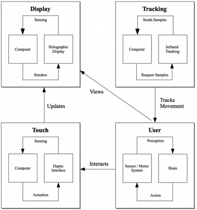
For a starting point, system designers need to consider the four main components of
a holographic user interface system. As seen in Figure 1.1, a standard system consists
of display, tracking, touch and human components. When operational, these user
inter-face components interact to produce a consolidated system which complement one another.
Moreover, the authors in [6] provide a detailed pros and cons list for each hardware choice.
From this list, we present a quick-start guide for our system design needs as seen in
Ta-ble 3.1. This list should serve as a starting point for aspiring system developers who aim to
Component Needs
Holographic Display Small field-of-view (FOV), Inexpensive to build,
Re-quires minimal physical space, No need for
per-spective viewing support, Relatively bright, Easily
portable, No need for special glasses
Tracking Lightweight, Inexpensive to build, Large
field-of-view infrared LEDs to maximize tracking, Easily
mountable to gloves
Haptic Feedback (Future Work) Lightweight, Inexpensive to build, Easily integrates
[image:37.612.91.527.100.313.2]with tracking gloves, Simple API for issuing feedback
Table 3.1: Hardware Component Needs
3.3.2 Developing Appropriate Interactions
Defining appropriate user interactions rely heavily on how users need to operate the system.
For example, try envisioning a physical task where a person picks up and throws a ball.
Now, try envisioning how this physical task can be translated to a keyboard and a mouse.
The user may hover over the virtual ball object and click the mouse to select the ball. After
the ball is selected, the user may give a swift mouse movement to trigger a ball throw.
In addition, the user may alter their ball’s trajectory by pressing a keystroke combination.
Limited to only their current controls, the user may quickly learn the ball grasping and
throwing procedure. However, this procedure forces users to learn a complex chain of
actions to accomplish a simple task; hence, it lacks intuition, a common human-centered
design practice.
For our system, consider a keyboard-less, mouse-less environment where the user must
be able to quickly learn interaction skills. Because we have access to user’s hands for
instead of using a mouse to select the ball, we can allow users to pinch two fingers to grasp
an object. Then, similar to a real-life movement, the user can flick their hand and throw
the ball. While the flicking motion relates to the traditional 2D mouse method, it is more
intuitive because the users’ hands are now their direct input device.
With these examples in mind, let’s think about general mechanisms for developing
ap-propriate interactions for a holographic user interface. Rather than focusing on how the
user should accomplish a task, we should focus on what the user wants to do. If successful,
a holographic user will allow users to focus on their tasks rather than their performed
ac-tions. We will discuss the precise user interface interactions in the upcoming section about
infrared tracking.
3.3.3 Presentation
When designing a futuristic user interface, presentation is the final component to consider.
Presentation defines the key traits which define our user interface and make it easy to use.
For example, button placement with respect to a text box is a part of the overall system
presentation. First, we must consider first-time system users. With any software user
inter-face, regardless of simplicity, a user must learn how to use it. At first, a new system can
be daunting and overwhelming. Nowadays, it is common for most video games to provide
walk throughs and basic task challenges to assimilate users into the interface’s controls.
Such online games as Zynga’sFarmville andCafe World immediately present tutorials to
first-time users. These tutorials engage users with simple tasks that allow them to gain
game knowledge without the burden of traditional ad hoc system learning. For our
sys-tem, we present first-time users a simple help tutorial which teaches them how to use the
infrared tracking gloves. By practicing user interface interactions such as pinching and
moving objects, future interface interactions will be more fluid and easy to accomplish.
Second, because our users will be positioned several feet farther away than traditional
computer users, it is necessary to present them with a low-clutter, large button graphical
user interface. At Microsoft Tech-Ed 2008’s developer conference, Mark Miller gave a
Figure 3.2: Holovee Help Tutorial for Hand Gesture Interactions
analyzed various Windows user interfaces and criticized Microsoft’s mechanism of user
interface design. Miller suggested such things as keystroke shortcuts and cluttered menus
caused more user complexity than intended. Moreover, noise or excessive word verbiage
leads to user confusion. To present the user with a clean user interface, we should
em-phasize relevant information with higher contrast colors and larger font size. In addition,
whereas traditional user interfaces worry about minimizing mouse travel distance, our user
interface should focus on minimizing excessive hand movement between user interface
controls to prevent user fatigue. While these design suggestions seem simple, so many user
interfaces do not take them into consideration.
Finally, we must present users with a fun, exciting experience. When interacting with a
futuristic user interface, users should feel energized and entertained by its unique behavior.
For example, Spore, developed by Electronic Arts, is a creature evolution game which
cre-ated an unrivaled enjoyment for users. Surely, the game’s concept of playing god alone was
very intriguing. However, the game’s real entertainment factor was its creature generator.
According to [38], in under a year, over 100 million creatures were created by users and
generator’s amazing entertainment factor which allowed users to create endless body part
combinations. With Spore in mind, we offer techniques to present users with a fun user
interface:
• Offer Full Control- If developing a builder application, allow users full creative
con-trol to shape their creations. Doing so, users will feel empowered and be excited to
unleash their imagination.
• Reduce Thinking - The less time a user has to think about remembering interface
interactions, the more time they can spend being consumed in their tasks.
• Animate User Interface Elements- In [28], John Lasseter, a Disney animator, states
that procedural concepts such as Squash, Stretch and Exaggeration should be applied
to create a unique character and story personality which entertains the audience. If
we apply those same animation principles, we can produce very exciting interface
controls.
• Inside Humor - Insert subtle jokes or comical character movements into the user
interface. The Sims, Electronic Art’s top-selling PC game, became popular because
of its quirky humor and taboo jokes.
3.4
Summary
In this section, we learned that human-computer interaction factors are deeply engrained
into futuristic user interfaces.
• Understanding the needs for a futuristic, holographic user interface are very
impor-tant. When developing a futuristic interface, system designers should consider
var-ious questions related to user experience, task completion and ergonomics for more
successful results. Moreover, while traditional 2D user interfaces are efficient for
ev-eryday computing, they often do not translate well when trying to complex complex
• Even if a proposed system’s technology is highly futuristic, it does not mean that a
solution is out of reach. We can think of imaginative solutions to create the illusion
of a futuristic design.
• When planning our system, we can use several Human-Center Design approaches to
distinguish between user interfaces ideas that are desirable, feasible and viable. Most
often, iterative software approaches which present pieces of functionality every
re-lease cycle, are successful for systems with fuzzy requirements and early unknowns.
• Choosing the right system equipment and futuristic user interface interactions heavily
rely on what the user needs to accomplish. Natural hand interactions such as grasping,
rotating and translation are much easier to achieve with futuristic controls. In
addi-tion, these techniques are much more fluid than traditional interaction techniques.
• A futuristic user interface’s overall presentation is the most important factor for
en-gaging potential users. The interface should go beyond initial user expectations and
create a fun, entertaining environment for them to see the true benefits of a futuristic
Chapter 4
Holovee: A Social Networking Application
4.1
System Design
4.1.1 Basic Overview
With a solid understanding of some best user interface design practices, we begin to
visu-alize how they can be applied to our social networking software application. We will be
presenting users with Holovee, a software application which allows them to manage and
manipulate their Facebook social networking data. The software application will be tightly
integrated with our infrared tracking and holographic display components. Before
defin-ing infrared trackdefin-ing interactions and other components, our software framework should be
well-designed and usable from a traditional 2D mouse-keyboard interface. We provide a
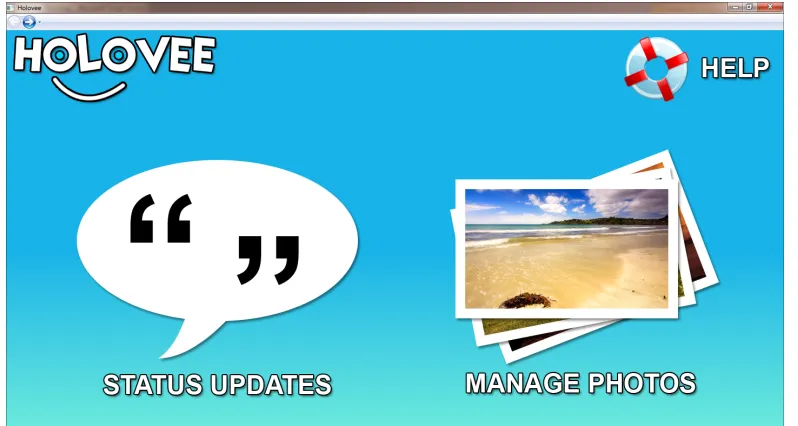
screenshot of the social networking software application in Figure 4.1.
Knowing our user interface needs, we can discuss how user interface controls were
positioned. When designing our user interface, we focus on providing users with less
clutter and simple interactions. Upon startup, the software application presents users with
two options: a button to manage their status updates and a button to manage their photo
albums. In addition, we make use of high contrast colors for the currently selected user
interface controls. High contrast colors will help users distinguish important user interface
items. As the user selects items, the interface items will dynamically update.
Again, this work’s end goal is to provide users with a fun, easy-to-use social networking
application. We do not desire to design a user interface which dictates how a user should
Figure 4.1: Holovee Main Screen
creatively. From our human-computer interaction study, we need to define tasks which the
user need accomplish with our interface:
• Manage and Manipulate Photo Albums - The user shall be able to rotate, scale and
manipulate their uploaded Facebook photo albums. Users will be able to add captions
and tag friends in specific photos.
• Easily Update their Facebook Status - The user shall be able to dictate their current
status and publish their information to the Facebook website.
• Search Friends - The user shall be able to search their friends list and view profile
updates.
These tasks will be a basis for our software application and serve as loose guidelines for
our user’s needs. Envisioning our rough software requirements, we can begin to formulate
4.1.2 Design Diagrams
From Figure 1.1, we showed a basic system component overview and each component’s
complementary interactions. For this section, we are only concerned with classes related
to our user interface design and functionality. In Figure 4.2, we illustrate our software
application’s class architecture. We break down our user interface into specific software
components which provide core functionality to our system. In upcoming sections, we will
discuss additional class diagrams that relate to our infrared tracking and speech tracking
components.
Figure 4.2: Basic Application Structure
Figure 4.2 shows the high level application classes which comprise our social
network-ing software application. From Figure 4.2, we can derive new functionality for our User
Photos and Friend Status pages as shown in Figures 4.3 and 4.4. For example, in 4.3, we can
visualize how our base Tile3DManager can be tailored towards displaying our user’s
Face-book photos. We have built various class helper methods into the PhotoTile3DManager
in photos. In addition, we created a FacebookPhotoLoader class to asynchronously load
photo objects into PhotoTile3D object classes. As seen in Figure 4.4, we create the same
type of subclass behavior for our friend status page class. We tailor our friend status
ob-jects instances toward interacting with Tile3D instances. Table 4.1 provides a description
of each application level class. These class descriptions are only a high level representation
of our software framework’s most important classes. They do not represent an exhaustive
definition of every software application class structure.
Application Class Purpose
FacebookManager Responsible for managing all interactions with the
Facebook Application Programming Interface (API).
Given a Facebook developer key and user login, the
FacebookManager can allow us to access all
pro-file, photo and friend information about the currently
logged-in user.
WiimoteManager Encapsulates the necessary components for
establish-ing a Bluetooth connection between the software
ap-plication and the Wiimote hardware device. Also, the
WiimoteManager allows various application
compo-nents to subscribe to Wiimote infrared tracking
up-dates.
SpeechManager Sets up the Microsoft Speech Recognition engine
which allows Holovee to recognize spoken
com-mands and dictation. The Microsoft Speech
Recog-nition allows developers to build grammars which the
application can distinctly infer to be application
com-mands.
Tile3D Allows Windows Presentation Foundation (WPF) 2D
Visuals to mapped to 3D cube objects. Tile3D
en-capsulates a 3D cube model representation and also
handles all animation responses to user interactions.
New 3D Holovee controls can derive from this class
to get basic interactivity controls.
Tile3DManager Controls all Tile3D objects which are added to its
in-ternal list. Includes basic functionality methods for
FacebookPhotoLoader Threaded background photo loader which handles
loading photos into the user interface. The
Face-bookPhotoLoader uses the FacebookManager to
in-voke the Facebook management API and
asyn-chronously load photo content.
FacebookFriendStatusLoader Threaded background status loader which handles
loading the current user’s friend status updates into
the user interface. The FacebookFriendStatusLoader
uses the FacebookManager to invoke the Facebook
management API and asynchronously load status
[image:48.612.99.517.99.334.2]content.
Table 4.1: Software Class Diagram Definitions
4.2
Programming the Framework
4.2.1 Choosing a Development Environment
For our development environment, we were looking for a development environment and
programming language which best fit our software application. As aforementioned, we
chose Microsoft Visual Studio 2008, Windows Presentation Foundation (WPF) and C#
be-cause of our familiarity with the technologies. In particular, there are plentiful resources
for quickly building WPF applications and creating dynamic graphical environments.
Win-dows Presentation Foundation is a graphical system which is based on DirectX and allows
developers to focus on building application components rather than programming for
application programming interface (API) for interacting with a computer’s graphics
hard-ware. However, again, we are looking for a programming technology which has an
abun-dance of resources. OpenGL has great tutorials and source code examples, but did not seem
fitting for quickly prototyping our application.
Because of Visual Studio’s great functionality, debugging applications is rather simple
and facilitates tracking software bugs. Another great thing about C# application
frame-works is that they can easily be reused in different applications. A standard DirectX
ap-plication consists of several main methods which are called during execution time. During
initialization, our application will present users with a main menu to manage their social
networking data. Users will use both speech commands and their infrared tracking gloves
to navigate the Holovee user interface.
As in any UI-based software application, there is a main message processing loop which
handles updating and drawing the user interface. Unlike a traditional DirectX game loop,
we do not have to define these update methods, but rather can subscribe to messages and
be notified via events. For example, if the user issues an Add Caption speech command,
this command will be applied to our user interface, allow a user to add a caption to their
currently selected photo. Again, we do not have to continually check for t
![Figure 3.1: IDEO’s Human-Center Designed Process viewed through a series lenses [20].](https://thumb-us.123doks.com/thumbv2/123dok_us/115226.11028/34.612.163.464.113.512/figure-human-center-designed-process-viewed-series-lenses.webp)


![Figure 5.1: The Electromagnetic Spectrum - Infrared Light is invisble to the human eye [13]](https://thumb-us.123doks.com/thumbv2/123dok_us/115226.11028/67.612.101.524.92.356/figure-electromagnetic-spectrum-infrared-light-invisble-human-eye.webp)
