Feng, Yue and Ren, Jinchang and Jiang, Jianmin and Halvey, Martin and
Jose, Joemon M. (2012) Effective venue image retrieval using robust
feature extraction and model constrained matching for mobile robot
localization. Machine Vision and Applications, 23 (5). pp. 1011-1027. ISSN
0932-8092 , http://dx.doi.org/10.1007/s00138-011-0350-z
This version is available at https://strathprints.strath.ac.uk/48402/
Strathprints is designed to allow users to access the research output of the University of Strathclyde. Unless otherwise explicitly stated on the manuscript, Copyright © and Moral Rights for the papers on this site are retained by the individual authors and/or other copyright owners. Please check the manuscript for details of any other licences that may have been applied. You may not engage in further distribution of the material for any profitmaking activities or any commercial gain. You may freely distribute both the url (https://strathprints.strath.ac.uk/) and the content of this paper for research or private study, educational, or not-for-profit purposes without prior permission or charge.
Any correspondence concerning this service should be sent to the Strathprints administrator: [email protected]
The Strathprints institutional repository (https://strathprints.strath.ac.uk) is a digital archive of University of Strathclyde research outputs. It has been developed to disseminate open access research outputs, expose data about those outputs, and enable the
Effective Venue Image Retrieval using Robust Feature Extraction and
Model Constrained Matching for Mobile Robot Localization
Yue Feng
1, Jinchang Ren
2*, Jianmin Jiang
3, Martin Halvey
4and Joemon M. Jose
51
Department of Forensic and Neurodevelopmental Science, Institute of Psychiatry, King‟s College London, London, UK
2
Centre for excellence in Signal and Image Processing, EEE Dept., University of Strathclyde, Glasgow, UK
3
Digital Imaging and Systems Research Institute, University of Bradford, Bradford, UK
4
Interactive System Group, University of Glasgow, Glasgow, UK
5
Multimedia Information Retrieval Group, University of Glasgow, Glasgow, UK
[email protected], [email protected], [email protected] and {halvey, jj}@dcs.gla.ac.uk
Abstract— This paper describes a novel system for mobile robot localization in an indoor environment, using concepts like homography and matching borrowed from the context of stereo and content-based image retrieval techniques (CBIR). To deal with
variations with respect to viewpoint and camera positions, a group of points of interest (POI) is extracted to represent the image for
robust matching. To cope with illumination changes, we propose to produce a contrast image for each video frame by using the root
mean square strategy, thus all the POIs are extracted from the corresponding contrast images to provide perceptually consistent
measurement of image content. To achieve effective image matching, modeling of robot behavior for model constrained matching is
proposed, where normalized cross correlation is employed for local matching to determine corresponding POI pairs followed by
homography based global optimization using RANSAC. Meanwhile, application of specific constraints also helps to exclude irrelevant
frames in the training set to further improve the efficiency and robustness. The proposed approach has been successfully applied to the
Robot Vision task for the ImageCLEF workshop, and the experimental results have fully demonstrated the high-quality performance
of our approaches in terms of both precision and robustness. The system and approach outlined in this paper was ranked the second
best in the optional task group in ImageCLEF 2009. In addition to demonstrating the merits of our approach in isolation, we also
illustrate the benefits of our proposed approach in comparison with other submissions.
Index Terms: content-based image retrieval, robot localization, computer vision, model constrained matching
*Corresponding Author:
Dr. Jinchang Ren
Centre of excellence in Signal and Image Processing Department of Electronic and Electrical Engineering University of Strathclyde
204 George Street Glasgow, G1 1XW United Kingdom
Tel. +44-141-5482384
I. INTRODUCTION
Robot vision has a wide range of applications in both science and industries such as aerospace, security, and military. For
example, in aerospace, the UAV (Unmanned Aerial Vehicles) airplane relies on a global positioning system (GPS) and visual
sequence captured during flying to navigate a route. This process requires the system to detect landmarks in order to determine
the position of the aircraft. Another example is in military services, robots are often used to explore an area that is too dangerous
for soldiers, i.e. in an effort to reduce casualties. These types of operations require the military robot to annotate its environment
so that it can be located. Thus, the requirement for constant and precise knowledge of the location and motion of the mobile
robot is extremely critical.
One of the key objectives in mobile robotics is to provide an autonomous mobile robot with the ability to take a role in
various tasks under different environments. To achieve this, the robot needs to be able to recognize its location; this can be
achieved through some sort of localization methodology and has led to an important topic and area of research, namely mobile
robot localization. Mobile robot localization has been a topic of interest for many years [16] [17], which aims to determine a
robot‟s position in a map or in a learned map. Given the initial robot position, local tracking is the problem of keeping track of that position over time. Global localization provides mobile robots with the capabilities to deal with initialization and recovery
from occlusion [18]. Visual based localization using natural landmarks is highly desirable in comparison with sensor based
localization. Sensors such as sonar sensors and range finders can suffer from problems due to reflections; this problem can be
eliminated when using only visual information for localization.
This paper describes our recent research on vision based mobile robot localization, which formed the basis of our submission
for the ImageCLEF 2009 Robot Vision task [1]. The goal of this task is to address the problem of topological localization of a
mobile robot using visual information. Given a test sequence, a system/algorithm must be able to provide information about the
location of the robot, where part of the relevant location information is available in the training set. Since the determined location
of the robot can be regarded as a kind of annotation, the corresponding task is considered as an extension of image annotatio n
and retrieval. Details of the task are discussed in Section II (B).
In order to provide a solution for the task outlined, we are proposing the following solution which attempts to address and
overcome many of the difficulties involved. The primary novelty of this paper is a methodology for obtaining robust feature
extraction for image representation together with model constrained matching scheme where the moving behavior of the robot is
modeled to guide the whole process, based on the concepts like homography and matching borrowed from the context of stereo.
First, a contrast image is produced for each video frame, which can provide a perceptually consistent measurement of image
content in spite of illumination changes. Secondly, a group of POIs is extracted from the corresponding contrast image for
behavior for model constrained matching of POIs is employed for both efficiency and robustness, where normalized cross
correlation and RANSAC are respectively applied to determine corresponding POI pairs and to determine a homography
between two sets of POI pairs. It is worth noting that the model specific constraints can help improve the matching performance
in terms of efficiency, accuracy and robustness by excluding irrelevant samples in the training set.
The remainder of this paper is organized as follows. In Section II, we describe previous state of the art in the area of robot
vision and outline the objectives of robot vision task in ImageCLEF 2009. In Section III, the basic POI detector and its improved
version using our derived contrast image are presented. In Section IV, modeling of robot behavior for model-constrained
matching is presented. Experimental results from ImageCLEF 2009 and discussions are presented in Section V, and finally some
concluding remarks are drawn in Section VI.
II. RELATED WORK
In this section we describe the state of the art in the area of mobile robot localization, including general solutions for this field
and specific requirements from ImageCLEF 2009. Since this is the first time a mobile robot vision task has been introduced in
the ImageCLEF workshop for benchmarking, the corresponding details for the task and workshop are also presented.
A. Previous Work in General Mobile Robot Localization
Castellanos et al. [20] propose a method for landmark-based map acquisition and robot localization where the use of external
mechanisms, such as a Charge-Coupled Device (CCD) camera and a 2-D laser rangefinder, are implemented. In the cases
addressed in this work, the robot followed a predefined trajectory and stopped at regular intervals to obtain information.
Complementary information was taken, by hand, which provided real locations of the robot with respect to a base reference. A
mapping algorithm with continuous localization has been proposed by Yamauchi et al. [21]. Sonar‟s, as well as laser rangefinders, were used with a greater confidence for the laser range data. The mapping was based on a certain exploration
method, called Frontier-Based exploration. The algorithms outlined are based on sensor models and configuration, and on how
detectable the selected features are. In the numerous cases where the sensor system can be unreliable, due to for example the
ultrasonic transducers or because of effects like specular reflections or cross-talk, these modeling methods have additional
problems. Moreover, these procedures are highly task dependent, so their parameters need to be re-adjusted to the conditions of
the specific environment under exploration.
Recently, more attention has been focused on vision based methodologies for robot localization, which has mostly been
adopted in robot navigation [2] and location recognition [3]. The main difficulty for vision based localization of robots is how to
learn and determine the views of an environment with respect to viewpoint changes, which can result in different illuminations
these factors are extremely critical for an effective system.
The most popular vision based methods can be categorized into landmark recognition, geometric recognition, object
recognition and probabilistic approaches. A great deal of previous work in this area relates to landmark-based methods, these
methods use local features to detect vertical lines or specific signs for controlling robot motion [7]. The types of systems that use
this approach usually require an a priori map of the environment. For example, Sim and Dudeck [22] use regions of the scene
and images with a high number of edges as natural landmarks. The main advantage of landmark-based methods is that they have
a bounded cumulative error. Although these features are easy to extract, they are not always available in image sequences.
Geometric methods mostly rely on sparse features such as POI and straight edges to describe a given scene, followed by an
image matching algorithm, in order to match visual features of query images with images in the database. For example, Althaus
et al. [8] use line features like detected edges to determine corridors and doorways. In Ohya et al. [6], an expectation image is
first rendered from training images as a model, and then the current location of the robot is determined by matching edges
extracted from the model image and a query image, respectively. However, their results are sensitive to the number of landmarks
in the image, plus it also relies on information from an ultrasonic sensor, thus it is not purely visual.
Localization by using object recognition techniques have proved to be a promising approach, as these methods utilize natural
features. Se et al. [23] use scale-invariant visual marks to deal with mobile robot localization based on the local feature detector
and the SIFT descriptor proposed by Lowe [24]. Wang et al. propose a strategy based on the Harris-Laplace interest point
detector and the SIFT descriptor [25]. In this system, each location is represented by a set of interest points instead of using all
pixels. The system then compares one frame to all frames in the database using a nearest neighbor search. Katsura et al. [26]
developed a system for detecting location in an outdoor local setting; the system can obtain the location by matching areas of
trees, sky, and buildings. However, the matching in their approach is severely affected by occlusions.
A probabilistic approach normally uses machine learning methods to learn the properties of different locations, and then
classify the query image into one of the classes based on the distance or probability between this image and every image class.
Torralba et al. [4] use global gist features [5] to train a Gaussian mixture model (GMM) representation for a set of locations.
Pronobis et al. [9] propose a method for visual place recognition by measuring the confidence level of the classification output
from a support vector machine (SVM), based on the distance between a query image and the average distance of training vectors
from each location. Since training classes usually need some prior knowledge of the training examples, they may produce
unsatisfactory results if there is a lack of training examples, such as the samples of unknown rooms. Moreover, this approach is
expensive in terms of computation. For example, for one single run it could take up to 2.5 days to finish, as reported in [9]. In
addition, the number of training classes will increase greatly due to the possible combinations of different rooms and different
Thus far we have highlighted various approaches to solve the difficult challenges associated with robot vision. In the
following subsection, we describe the difficulties, challenges and the details of the new robot vision task from ImageCLEF 2009.
B. Robot Vision Task in ImageCLEF Workshop
According to the official webpage, ImageCLEF is the cross-language image retrieval track run as part of the Cross Language
Evaluation Forum (CLEF) campaign starting from 2003 [19]. In ImageCLEF 2009, a robot vision task for mobile robot
localization was introduced, with the aim of retrieving robot images using visual information. Accordingly, a task of high
priority is defined and participants are asked to provide information about the location of the robot separately for each test image
when only some of the images from the test sequences are available or the sequences are scrambled. This corresponds to the
problem of global topological localization, where continuity of temporal information is not required. Meanwhile, an optional task
is also defined for robot localization, in which exploiting continuity of the sequences and relying on the test images acquired
before the classified image is allowed. It should be noted that for the workshop that an algorithm would be considered invalid if
future frame information is used to classify current ones. Since temporal information has been employed in our approach for
refined matching, our work is in the optional task group.
The robot vision task at ImageCLEF 2009 provided users with a common dataset and test bed on which state of the art
techniques on robot localization techniques can be evaluated and ranked. For all the participants, a group of training data
consisting of image sequences recorded in an indoor environment at a given time is provided, which includes a five-room
subsection (kitchen, printer area, one-person office, two-person office and corridor) under three different illumination conditions
(sunny, cloudy and night). The challenge for the participants in the robot vision task is to build a system able to answer the
question 'where am I?' (I'm in the kitchen, in the corridor, etc), i.e. to assign each test image to one of the five venues or to
indicate that the image comes from an unknown room. Moreover, the systems were allowed to refrain from making a decision
(e.g. in the case of lack of confidence). As the moving speed of the robot is assumed to be limited, this allows the image
matching function to work on a predictable range of possible matches.
The floor plan of the environment and samples of different rooms under different illumination conditions are shown in Fig.1
and Fig.2, respectively. As shown in Fig. 1, the five locales have quite different layout and settings. Though they can easily
identified by humans, provided the whole „image‟ of the venue is seen. However, as shown in Fig. 2, this becomes very difficult when only a very small part of the venue can be observed by the robot, additional difficulties for the task include variations in
illumination conditions and camera view point. Since the test images are acquired 6-20 months after the training sequence, such
variations are unavoidable and also may introduce more difficulties as discussed below.
One additional difficulty is introduced due to the unpredicted content changes in the captured images, which include adding,
decorators and small objects on the table, etc. Consequently, matching of images for robot localization needs to be insensitive to
such changes.
Fig 1. Map of an office environment.
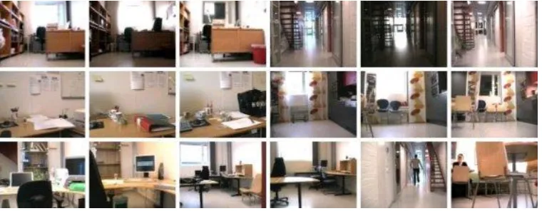
Fig 2. Sample frames in the training sequences. From top left to bottom right, the first 15 form 5 groups of images under 3 illumination conditions, which are
captured from five venues including single-person office, corridor, printer area, kitchen, and person office, respectively. The last three images are
two-person office, corridor and kitchen, and they are used to show the content changes in comparison with other sample images within the same venue.
In addition, rooms which are excluded from training but used for testing also make the whole task more challenging. Since
the office venues share common environmental and building conditions, as shown in Fig. 2, their images appear of quite similar
background and comparable furniture settings. As a result, to locate an unknown room becomes an extremely hard problem for
[image:7.612.213.409.117.366.2] [image:7.612.118.498.403.551.2]To overcome these difficulties, we have proposed robust point based feature extraction and model constrained matching
towards automatic robot localization in the robot vision task in ImageCLEF 2009. The system is mainly designed for use in
autonomous navigation, where limited knowledge of the environment is available. The main assumption here is that the content
information extracted from the scene provides enough features for matching. It is worth noting that this is achieved using vision
based methods rather than external sensors, and the relevant details are discussed in the next two sections.
III. ACCURATE AND ROBUST DETECTION OF POIS
A key requirement for real-time robot location detection system is its fast performance on image matching. The matching
problem that we have to solve, in order to find the images in the database that are most similar to the ones taken by the mobile
robot, is one of so-called intensity-based image matching via full search [25]. This method captures the similarity between the
intensity profiles of the two images. Given an intensity value at one pixel from one image, it searches looping through all the
pixels on the other image to find the best match. This creates a problem of system efficiency, as for example pixels in the
homogeneous texture domain contain high redundancy. Therefore, in our approach special attention is paid to selecting regions
with higher information content instead of using all pixels.
Detection of POIs has recently received increasingly attention in the computer vision domain. An interest point is a point in
the image that is rich in terms of local information content. In addition, an interest point is stable under local and global
perturbations in the image domain, including deformations such as those arising from perspective transforms as well as
illumination variations, such that the interest points can be reliably computed with high degree of reproducibility. Considering
these characters, image matching via POI can be a good solution for our task for finding relevant images in image search,
especially given its performance in illumination variations. In our approach, we have chosen corner features as POI since corners
are discrete and partially invariant to scale and rotational changes.
A. Original Harris Detector
One of the most commonly used POI detection methods in computer vision applications is the Harris corner detector [10],
which is used in our system as it is invariant to rotation, scale, illumination variation and image noise [38]. The Harris corner
detector is based on Harris and Stephens improved upon Moravec's corner detector [11], by considering the differential of the
2 2 ) , ( 2 ) , ( 2 ) , ( 2 ) , ( 2)
,
(
)
,
(
)
,
(
)
,
(
)
,
(
y y x y x x w y x w y x w y x w y xI
I
I
I
I
I
y
y
x
I
y
x
y
x
I
y
x
y
x
I
x
y
x
I
w
I
A
(1)where an image is given by I;
w
represents an image patch over the area; (x,y) is a set of pixels around; and the angle bracketsdenote an averaging process.
The “cornerness” response function of the Harris corner detector is based on the determinant and trace of the autocorrelation
matrix, where
k
[
0
.
04
,
0
.
15
]
as suggested in the literature [11].2
))
(
(
)
det(
A
k
trace
A
M
ha rris
(2)B. Dealing with Illumination Changes
Although the conventional interest point detectors (IPD) can successfully locate corner points in images, generally they will
fail or show lack of robustness when there are large illumination changes. To cope with the illumination changes in images, we
detect points of interest from a normalized image, rather than the original image. Let
be a normalization function, theimproved detector
M
propis defined in Eq. (3) below, whereB
is the autocorrelation matrix of the normalized image and)
(
ˆ
I
I
is the image of normalized contrast.2
))
(
(
)
det(
B
k
trace
B
M
prop
(3)
2 2ˆ
ˆ
ˆ
ˆ
ˆ
ˆ
)
,
ˆ
(
)
,
,
(
y y x y x xI
I
I
I
I
I
w
I
A
w
I
B
(4)As seen, the normalization function
is the key to the solution above, where several typical options can be summarizedas follows. In [12], Gevrekci et al. reported an approach called illumination robust feature extraction transform (IRFET). The
idea is to stretch the image contrast as a function of intensity, in order to span the space of possible photometric transformations
and to help to simulate a particular illumination condition. The contrast function introduced in that paper is given by
, ) (
1
1
))
,
(
(
Ixy cIRFET
e
y
x
I
(5)parameter to determine the slope of the sigmoid function. Since
IRFET is obtained forc
[
0
,
1
]
with a step size of 0.05, theoverall results are very sensitive to the selection of
c
from its 200 candidate values. Unfortunately, for a given image the methodto select a suitable
c
is undetermined. As a result, for an image pair it may be required to match200
200
times to achieve thebest result in dealing with illumination changes.
To overcome this drawback, we have adopted a different strategy for dealing with illumination changes. According to the
characteristics of human visual perception, the details that we can observe from an image depend on a local contrast ratio rather
than the intensity and this can be applied in our system to yield normalized image of refined contrast. We have considered three
typical contrast functions including Weber, Michelson, and Root Mean Square as will be discussed below.
Weber contrast function [12] focuses on the luminance of the pixel and the background luminance.
b b weber
I
I
y
x
I
y
x
I
(
,
))
(
,
)
(
(6)where
I
(
x
,
y
)
andI
brepresents the luminance of the pixel and the background luminance, respectively. This function iscommonly used in cases where small features are present on a large uniform background, i.e. the average luminance is
approximately equal to the background luminance. However, this seems unsuitable for our task, as we intend to enhance the
contrast of the background for effective extraction of POIs, rather than enhance the contrast of the foreground objects.
Michelson contrast [13] is another commonly used method to deal with luminance adjusting, which is defined as:
min max min max
))
,
(
(
I
I
I
I
y
x
I
Michelson
(7)where
I
max andI
min refer to the maximum and the minimum intensity in an image region or a whole image. Due to the nativeof the definition, this function is sensitive to noise, especially when there are isolated bright and/or dark pixels.
Root Mean Square (RMS) contrast is defined as the standard deviation of the pixel intensities below [30],
1 0 1 0 2)
)
,
(
(
1
))
,
(
(
N x M yRMS
I
x
y
I
MN
y
x
I
(8)where
I
x
,
y
is the intensity value of an image region sized M*N,I
is the corresponding average intensity which has beennormalized to 1. As can be seen, RMS is insensitive to isolated noisy pixels and also helps to enhance the contrast of background
pixels, as the standard deviation used can naturally smooth such noise and reflect the level of intensity changes in a local
neighborhood. Consequently, the resulting image can keep fine details and enable effective extraction of POIs for matching.
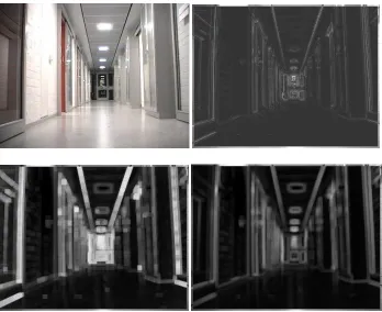
For a given image, the contrast images obtained using the three functions above are shown in Fig. 3, where a
5
5
localintensities differ significantly from neighboring ones, such as the ceiling lights, though it generates less noise. On the contrary,
the result of Michelson contains a great deal of noise as a result of abrupt contrast changes. Finally but not surprisingly, the result
from RMS appears to be the best among this group of results. This is due to two main reasons: The first is normalized average
intensity to overcome the effect of illumination changes, and the second is the root-mean-square processing used to help
constrain noise [30]. Consequently, RMS has been employed in our system to generate a normalized contrast image in dealing
with illumination changes.
Fig 3. One original image (top left) and three contrast images obtained using functions of Weber (top right),
Michelson (bottom left) and RMS (bottom right), respectively.
[image:11.612.133.481.197.481.2] [image:11.612.121.490.537.680.2]Based on the original image in Fig. 3, Fig. 4 shows results of extracted POIs using Harris detector (implemented in OpenCV),
where the left and the right images are those extracted from the original image and the RMS contrast image, respectively. Unlike
POIs extracted from the original image, POIs extracted from the RMS contrast image can reject those unreliable points on
homogeneous regions like the floor whilst keeping useful points. Although RMS helps to reduce false corner points, it has
detected much more corner points near the right boundary of the image and also one the door in the central area of the image. In
other words, it helps to re-balance the distribution of the corner points in comparison to those detected from the original image.
As a result, noise is suppressed towards more robust image matching in the next stage.
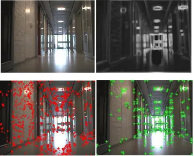
To provide further validation for our proposed strategy, we present another example of group of results of extracted POIs in
Fig. 5, where the input image is under different illumination conditions. Again, most of unreliable POIs have been reduced whilst
keeping useful points. These examples demonstrate the effectiveness of our introduced strategy in dealing with illumination
changes. In the following section we outline our approach for introducing constraints on the model that we apply for robot
localization.
Fig 5. Another group of results under different illumination conditions: the top left one is the original image, and the top right one is its RMS contrast image. The
[image:12.612.119.497.350.655.2]IV. MODEL-CONSTRAINED MATCHING FOR ROBOT LOCALIZATION
Given the extracted POI in both training and test sequences, the next step is to compute the similarity between each test frame
and all the frames in the training sequence to find the best match, so that the test frame will be annotated as the venue associated
with the matched frame of the training set. To improve both efficiency and accuracy, application specific constraints are applied
for matching the POIs. This strategy for feature matching and the relevant details for model-constrained frame annotation are
outlined in the following subsections.
A. Application Specific Modeling of Robot Behaviors
By studying the environmental settings and the training sequences released as part of the Robot Vision task in ImageCLEF 2009,
we find that the robot does not move „randomly‟ and that the robot‟s behavior is somewhat constrained by environment settings. These constraints can be summarized into three rules as follows.
Rule 1: Time length. The period of time that the robot stays in one venue is always more than 3 seconds, i.e. 15 continuously
frames at 5fps. Accordingly, the robot will not stay in one place for a period less than
N
0 frames, whereN
0 is determined asbeing 20 as a result of statistically analyzing the training sequences.
Rule 2: Jumping room. The robot has to cross the corridor before it enters other venues such as kitchen, offices and printer
area. In other words, the robot cannot bypass the corridor to go from one venue to another, i.e. jumping room is not allowed.
Rule 3: Unknown rooms. Since the test sequence contains additional rooms that are not included in the training sequences,
no corresponding frames in the training set could be used to annotate these rooms. In addition, due to the nature of the image
matching algorithm, that one test frame will be annotated with the most similar frame in the training set, a false annotation seems
unavoidable. In our system, however, it was found that the consistency between the unknown frame and the training frames is
very limited. This forms another rule for identifying unknown rooms, i.e. any test frame whose consistency below a given
threshold will be annotated as an unknown room, details on how to define this consistency are outlined in Section IV(C).
The rules described above have been generated by observing the data set and the behavior of the robot; it could be said that
they are very specific for the robot vision task from ImageCLEF 2009. However, this type of methodology can be adapted and
applied to other data sets for robot vision and localization, as in general the motion behavior of a robot is always constrained in a
given closed environment. As the focus of this paper is on the application of the methodologies outlined above, we reserve the
exploration of a more general solution for future work.
B. Model-constrained Matching
In order to facilitate the application of the three rules for robot localization outlined above, a model-constrained feature matching
exhaustive matching with all of the frames in the training set is required. Accordingly, the test frame will be classified into one of
the 6 possible venues including printer area, corridor, two-person office, one-person office, kitchen or unknown room (applying
Rule 3). Following on from this, the remaining two rules are applied as part of the matching process as follows.
If the robot is found within a venue for less than
N
0 frames, full search is once again applied. Otherwise, the localization istreated as stable (applying Rule-1) and the localization process will move to the next step (applying Rule 2).
Suppose the robot is determined to be stably in a specific venue rather than the corridor, in the next frame the robot can only
appear in two venues, i.e. either remaining in the same venue or entering the corridor. As a result, the next test frame is only
matched against the training frames from the same venue and the corridor, i.e. a much smaller subset in comparison with the
entire training set. This will not only improve the efficiency but also improve both the accuracy and robustness of our approach
for robot localization.
If the robot is found stably in the corridor, it will remain in the corridor or move into a new venue. Accordingly, the next
frame can be matched with all training frames with the exception of those within previous localized venues. In order to achieve
this, the path history of the robot is recorded, and only the last non-corridor venue is excluded in matching for flexibility, i.e. to
allow the robot indirectly revisiting a venue.
Considering that both the training and test sequences are captured using the same camera in the same geographic condition,
we assume that frames taken in the same location will contain similar contents and consistent geometric information. Thus, our
matching process needs to consider this similarity and consistency. The process of matching frames using extracted POIs is
discussed in full in the next subsection.
C. Strategy for Feature Matching
Inspired by stereo image matching which computes the disparity map of a sequence by estimating the similarity between the left
and right channel of image, we consider the training and test sequences as a stereo image sequence in our experiment. Thus, we
applied a similar procedure to compute the similarity.
Suppose the matching can be represented by the homography between POIs of an image pair, then POIs mapped from one
image to the another image would coincide exactly with their correspondences. Generally, the homography is only an
approximation of the mapping, thus mapped POIs cannot coincide exactly, i.e. containing false matches. The acceptance of a
putative matching is then to be considered in more detail, this will be discussed in two steps as follows.
1) Local matching to find corresponding POI pairs
For a given POI in a reference image
I
1, its corresponding POI in imageI
2 is determined via local image matching usingfrom
I
1 andI
2, respectively. For eachx
i inI
1, its best correspondencey
j* inI
2 is determined using NCC as))
,
(
(
max
arg
*
] , 1 [ 2 k i N ky
x
NCC
j
(9)
W W j i I y I I x I I y I I x I y x NCC 2 2 2 2 1 1 2 2 1 1 ) ~ ( ) ~ ( ) ~ ( ) ~ ( ) ,( (10)
where
x
~
belongs toW
(
x
i)
, a local window inI
1 centered atx
i andI
1 is its mean intensity. Similarly,~
y
W
(
y
j)
, a localwindow in
I
2centered aty
j andI
2 is its mean intensity.If there is another correspondence
(
i
'
,
j
*)
determined before, choosei
*
as the matched point forj
*
by*))
,
(
(
max
arg
*
} ' , {j
m
NCC
i
i i m
(11)In addition, if the associated NCC value is less than a given threshold
t
ncc, the determined point correspondence is treated asinvalid. In our system,
t
ncc is set as 60% of the maximum NCC value among all POI correspondences.2) Global matching using RANSAC
Once an initial set of POI correspondences are obtained using NCC, the next step is to verify these local correspondences
using a global constraint, where homography among these matched pairs of POI is determined to achieve affine-invariant
matching of images. The idea behind is based on the fact that images captured from one particular scene in testing and training
sets can be regarded as stereo pairs. This is because these images are captured by the same robot under various viewpoints along
with possible change of lighting conditions. As a result, these images should share common contents with limited difference that
can be tolerated during our homography-based matching. On the other hand, a failed matching may indicate that the test image
does not belong to the venue associated to the training one.
To determine the homography between two sets of POI obtained for the test image and the training image, the RANSAC
algorithm [14] is used to select an optimized subset of their matched POI correspondences. When the homography is determined,
the number of matched POI pairs from the RANSAC algorithm is then denoted as a degree of consistency measurement between
the images. Meanwhile, POIs which are excluded in the matching are treated as outliers and disregarded for robustness.
According to the POIs extracted from the images in Fig. 5, examples of matched points from two images with different
illumination conditions are shown in Fig. 6, where a pair of corresponding POIs is represented by „green *‟ and „red +‟. As can
be seen in the example, the approach that we have adopted has successfully filtered inconsistent POIs towards reliable matching
of images. It is also noteworthy that there are mis-matched points in Fig. 6, and these are mainly due to the fact that the images
tolerance in the algorithm for robustness. As a result, global matching can still generate satisfactory results despite of these errors
[image:16.612.96.522.112.275.2]in matching.
Fig 6. The matching map, the points linked with lines refer to a pair of matched POIs.
When a test image is compared with all frames in the training set, each homography-constrained matching determined by
RANSAC generates a measurement of consistency. Rather than specifying the test image into the venue class of the frame who
has the highest consistency measurement among all images in the training set, for robustness the first
N
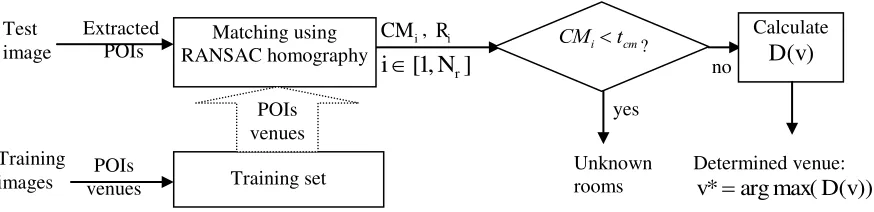
r best matched frames ofhighest consistency measurement are obtained to make the final decision. In addition, a diagram of our global matching scheme
is presented in Fig. 7 to further explain how it works, and details of which is described below.
Fig. 7. Block diagram of our global matching scheme.
Let
CM
i andR
i respectively refer to the value of consistency measurement and associated venue of thei
th best match fromRANSAC, where
CM
i
CM
j ifi
j
fori
,
j
[
1
,
N
r]
, i.e.CM
1 is the match of highest consistency measurement. If1
CM
is less than a given thresholdt
cm, the matching is considered unreliable, which means that the test image has no satisfiedmatches in the training set. In other words, it is most likely that the test image comes from a venue excluded from the training Matching using
RANSAC homography Test
image
Extracted POIs
Training set POIs venues
i
CM
,R
i]
,
1
[
N
ri
Training
images venues POIs
CMitcm
?
yes
Unknown rooms
no
Calculate
)
(v
D
Determined venue:
))
(
max(
arg
*
D
v
[image:16.612.89.526.460.566.2]set, i.e. an unknown room. As a result, Rule 3 in Section IV(A) is applied to identify such cases, where
t
cm is empirically set as15. Otherwise, the test frame will be associated with one of the five known venues as follows.
Let
v
be one of the five given venues in the training set, for each of them a matched degreeD
(.)
is determined as)
,
(
)
(
v
CM
Tag
i
v
D
i i
(12)
otherwise
v
R
if
v
i
Tag
i0
,
1
)
,
(
(13)Then, the test frame is annotated of the venue of maximum matched degree, i.e.
v
*
arg
max(
D
(
v
))
. This is consistent withour assumption that the location can be retrieved by finding the most similar frame in the training sequence to the test sequence.
As a result, the most similar frame should contain the most number of POIs to match with the test frame.
V. RESULTSANDEVALUATION
The proposed approach which has been outlined above was applied for mobile robot localization task in the ImageCLEF
workshop in 2009, and the results are summarized and analyzed in this section.
A. Data Set and Evaluation Criteria
In the robot vision task of ImageCLEF 2009, a subset of KHL-IDOL2 database [27] is used for both training and testing. For
each of the three illumination conditions, i.e. cloudy, sunny and night, there are four training sequences which are captured by a
camera mounted on a mobile robot. Data from two robots are provided, which form 24 sequences in total. During the testing
stage, a single sequence of unknown illumination condition is utilized, which contains new venues which are excluded from the
training sequences.
To enable quantitative evaluations, annotated results are introduced in the captured sequences to denote the position of the
robot. Such information is available in the training sequences as ground truth maps, and a score is used to measure the accuracy
of annotated results in comparison with the ground truth. Actually, the score here attempts to reward systems for correctly
annotating frames and also penalizing systems for incorrectly annotating frames, thus giving an overall indication of
performance. The following rules are used when calculating the score for a single test sequence: +1.0 points for each correctly annotated frame.
Correct detection of an unknown room is treated the same way as correct annotation.
-0.5 points for each incorrectly annotated frame.
In fact, a script is also provided by the ImageCLEF organisers to enable participants to evaluate the performance of their
algorithms/systems as this script will generate a score for each annotated sequence by comparing it with the ground truth.
According to the obtained scores, all the systems were then ranked and systems of higher scores are considered to be better than
those of lower scores.
B. Preliminary Evaluation using Training Sequences
To measure the performance of our proposed approach over training sequences, two groups of experiments are implemented. In
the first group, sequences under the same illumination conditions are used for training and testing. In the second group, on the
contrary, sequences of different illumination conditions are mixed together during the training and testing process. Certainly, the
first group will generate better results than the second group, but the second group is more practical and indeed a more robust
evaluation matching the requirements of ImageCLEF.
In each group of experiments, results of three solutions are compared. The first solution uses only conventional method for
detecting POIs, followed by a coarse point matching, and this can be regarded as baseline. The second solution adopts
illumination normalized scheme in the extraction of POIs, where the matching scheme remains the same. The third solution is
achieved by introducing model-constrained matching into the second solution, thus it can be considered as a much improved
[image:18.612.52.297.449.608.2]version of the baseline system.
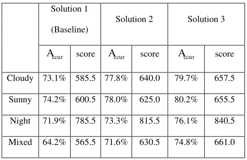
Table 1. Performance of three solutions using cross validation
Solution 1
(Baseline)
Solution 2 Solution 3
ccur
A
scoreA
ccur scoreA
ccur scoreCloudy 73.1% 585.5 77.8% 640.0 79.7% 657.5
Sunny 74.2% 600.5 78.0% 625.0 80.2% 655.5
Night 71.9% 785.5 73.3% 815.5 76.1% 840.5
Mixed 64.2% 565.5 71.6% 630.5 74.8% 661.0
Herein, cross validation is employed for performance evaluation, where 75% of the training sequences are used for training
and the remaining 25% for testing. The average accuracy
A
ccur and score obtained are reported in Table 1. As can be seen, theproposed contrast-based illumination normalization and model-constrained matching indeed can improve the accuracy of the
annotation results. In addition it can be seen that such improvements become significant when data of mixed illumination
Also, it should be noted that a high score may be obtained even the annotation accuracy is low; this can be seen particularly
in the results in the third row, i.e. from night conditions. This is brought about because the score and the accuracy are defined in
an inconsistent manner. As mentioned above, the score is defined as an accumulated reward or penalty, and the accuracy is an
average percentage of correctly annotated frames. Since the reward of 1.0 is higher than 0.5 for penalty, a longer sequence will
certainly produce a higher score provided that an average accuracy of more than 50% is achieved. In fact, the sequences from
night conditions are the longest in the whole group, and this explains the results in Table 1. Nevertheless, under a given test
sequence such inconsistency can be disregarded, thus the final evaluation achieved is still consistent.
To further analyze the annotated results, a confusion matrix is generated and shown in Table 2. This table provides an
indication of how accurate the localization is in terms of the five venues including printer area, corridor, two-person office,
one-person office and kitchen (see for details in Fig. 1 in Section II). Based on the results in Table 2, several observations can be
made and summarized as follows. Firstly, due to the similarity between corridor and printer area, about 7.1% printer area and
11.8% of corridor frames are mis-annotated as the other. Secondly, the accuracy in annotating two-person office is the highest at
nearly 87% due to its significant difference from other venues. Thirdly, due to two reasons the accuracy for annotating
one-person office is the lowest at about 75%. One is its narrow layout which makes it appear like the corridor. The other is the
rectangle-shaped tables, which are very similar to the settings in the kitchen. As a result, 8.1% and 8.7% of one-person office
frames are mis-annotated as either corridor or kitchen respectively. However, only 3.4% of corridor frames are mis-annotated as
kitchen. Fourthly, about 10.3% of kitchen frames are annotated as one-person office, this again is due to the similar contents
inside these frames. Finally, the average accuracy achieved is around 80.3% for the five venues, and this shows the effectiveness
[image:19.612.74.321.539.665.2]of our proposed approach.
Table 2. Confusion matrix for the annotation results of five venues including printer area,
corridor, two-person office, one-person office and kitchen.
Printer area Corridor Two-person One-person Kitchen
Printer area 82.2% 7.1% 2.9% 3.3% 4.5%
Corridor 11.8% 80.0% 2.7% 2.1% 3.4%
Two-person 2.8% 4.5% 86.9% 2.5% 3.3%
One-person 6.1% 8.1% 1.9% 75.2% 8.7%
Kitchen 4.8% 2.6% 4.2% 10.3% 78.1%
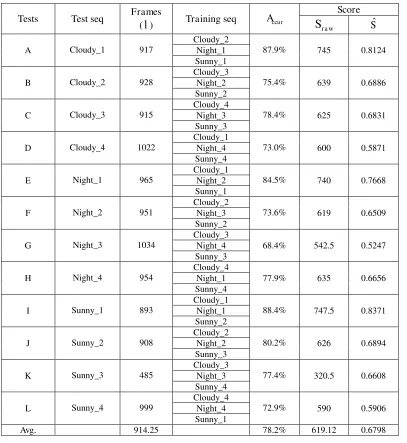
To further evaluate the performance of our proposed method, cross validation using 12 sequences provided by ImageCLEF
Different combinations of these sequences form 12 tests and the results are report in Table 3. As can be seen, an average score of
619.12 is obtained, which corresponds to an average accuracy of 78.2%. Also please note that under same accuracy, the scores
can be significantly different, see for example for the tests in groups H and K. To overcome such inconsistency in evaluation, we
introduce a normalized score
S
ˆ
defined asS
ˆ
S
ra w/
l
, whereS
r a wis the raw score obtained using previous evaluations andl
refers to the number of frames in the test sequence. Accordingly, normalized score for each test is calculated and also compared
in Table 3. As seen, for test groups H and K, their normalized scores are quite similar to each other, thus the proposed
[image:20.612.81.488.251.694.2]normalized score
S
ˆ
provides a more consistent measurement of performance with the obtained accuracy.Table 3. Results of cross validation to further validate the effectiveness of proposed method.
Tests Test seq Frames
(
l
) Training seqA
ccurScore r a w
S
S
ˆ
A Cloudy_1 917
Cloudy_2
87.9% 745 0.8124
Night_1 Sunny_1
B Cloudy_2 928
Cloudy_3
75.4% 639 0.6886
Night_2 Sunny_2
C Cloudy_3 915
Cloudy_4
78.4% 625 0.6831
Night_3 Sunny_3
D Cloudy_4 1022
Cloudy_1
73.0% 600 0.5871
Night_4 Sunny_4
E Night_1 965
Cloudy_1
84.5% 740 0.7668
Night_2 Sunny_1
F Night_2 951
Cloudy_2
73.6% 619 0.6509
Night_3 Sunny_2
G Night_3 1034
Cloudy_3
68.4% 542.5 0.5247
Night_4 Sunny_3
H Night_4 954
Cloudy_4
77.9% 635 0.6656
Night_1 Sunny_4
I Sunny_1 893
Cloudy_1
88.4% 747.5 0.8371
Night_1 Sunny_2
J Sunny_2 908
Cloudy_2
80.2% 626 0.6894
Night_2 Sunny_3
K Sunny_3 485
Cloudy_3
77.4% 320.5 0.6608
Night_3 Sunny_4
L Sunny_4 999
Cloudy_4
72.9% 590 0.5906
Night_4 Sunny_1
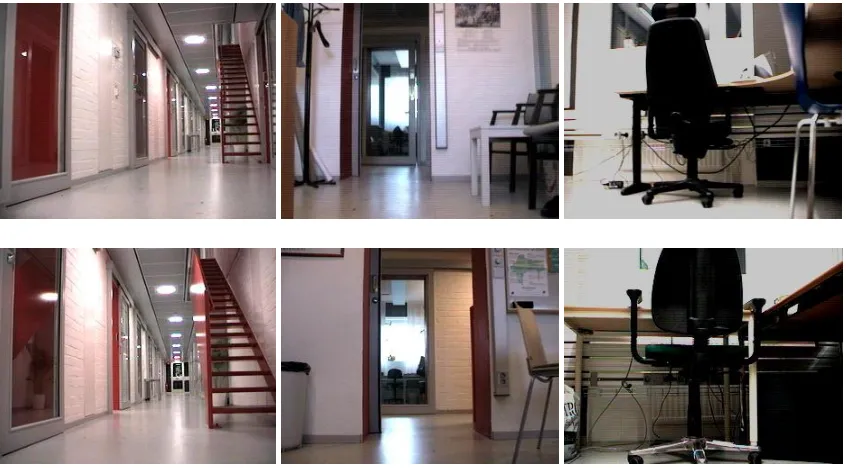
To illustrate the similarity between frames from different venues, Fig. 8 gives six typical frames extracted from the training
set, which form three pairs shown in three columns. As can be seen, each pair of images is of quite similar content and layout but
annotated differently. In other words, this shows the difficulty in venue determination for automatically robot localization using
vision only information. As a result, the relative high accuracy achieved appears reasonably good.
Fig 8. Examples of typical frames to illustrate the similarity of frames from different venues: The left column is from printer area and corridor; the middle
column is from two-person office and kitchen; and the last column is from two-person office and one-person office, respectively.
C. Performance of ImageCLEF Official Evaluation
As mentioned previously, in the official evaluation only one sequence with unknown illumination condition and newly
introduced venues was utilized. Based to the results announced by ImageCLEF 2009, the scores for the first four teams/systems
are summarized in Table 4, where our proposed system is ranked as being second in the optional task group [29]. As can be seen,
the best results achieved by the first three teams are quite comparable with a score around 900, for all of these approaches this is
mainly due to the usage of neighboring frames in the past. Without utilizing this neighboring information, as reported in another
task group, the highest score achieved is only 793.0 by the IDIAP team [19].
Table 4. Results of the best 4 systems and their scores [19, 32]
Team/System SIMD Proposed CVIU IDIAP
[image:21.612.96.519.164.398.2]It is worth noting that using neighboring frames after the current frame may significant improve the accuracy. For example,
in a system proposed by CVIU the label of a test frame is iteratively corrected to the most frequent label in the sequence of ±20
frames until convergence. Using such a smoothing procedure, a score of more than 1000 can be achieved. However, this is
considered based on the rules of the robot localization task as invalid because the annotation relies on future information after the
frame which is being annotated, which means that it is almost impossible to make a real time decision about the current location.
In the following, techniques used by the other three teams listed in Table 4 are discussed and compared. In the SIMD system
[33], a Monte-Carlo particle-filter is used to track the robot pose with extracted scale-invariant feature transform (SIFT) features
to update the tracker. The pose
(
x
,
y
,
)
includes 2D position(
x
,
y
)
and an orientation
of the robot. Despite the highcomplexity, this solution seems to lack flexibility, as the training process also relies on information provided by a distance sensor
rather than only the camera output. In the CVIU system, a Gaussian gradient on the L component of the LAB color space is
utilized as the main feature together with histograms from a three-tie spatial pyramid. Then a SVM is employed to compute the
probability of a test frame to each room. Finally, a smoothing procedure is applied as post-processing by exploring multiple
images, i.e. the label of a test frame is corrected to the most frequent label in the sequence of the past 20 frames. Although the
smoothing procedure seems to satisfy the requirements of ImageCLEF 2009, details on how to avoid mis-annotation when the
robot moves from one location to another are absent as this appears to be corrected via smoothing. In the IDIAP system, the main
techniques used include Composed Receptive Fields Histograms (CRFH) and SIFT features in combination with a
Harris-Laplace detector, a Generalized Discriminative Accumulation Scheme (G-DAS) and SVM classifier, and relevant details can be
found in [15, 28]. Temporal filtering for smoothing the results is also applied using five images before the classified image.
In summary, point based features like SIFT and POI detector are widely used in this task, including the system from SIMD,
IDIAP and us. Without complex features, tracking and learnt classifiers, our proposed method has yielded a reasonably good
performance. Further analysis of the errors in annotation is discussed in the next section.
D. Analysis and Discussions
Using the available information, it is interesting to compare the annotated results from our system and SIMD with the published
ground truth maps, and the results are shown in Table 5. In 1690 frames of the test sequence, our approach can correctly annotate
1157 frames with an accuracy of about 68.5%. On the contrary, the accuracy of SIMD is only 63.8% if the rejected frames are
considered as incorrect. However, SIMD has gained a higher score than our system because of the penalty caused by many more
incorrectly classified frames in our system. Again, this shows the inconsistency of evaluation using the accuracy and score
In 533 misclassified frames, 227 or 42.6% of them are from unknown rooms, i.e. absent from training sequences. In total 121
frames are classified as being from unknown rooms in our system, of which 114 or 94.2% frames are correct. In other words, we
[image:23.612.57.295.166.239.2]have a low recall rate but a pretty high precision rate in detecting unknown rooms.
Table 5. Detailed results from SIMD and our system
Team/System Correct Wrong Reject Accuracy
SIMD 1072 311 297 63.8%
Our 1157 533 0 68.5%
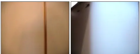
When analyzing the errors in our system, it is found that most of the incorrectly annotated frames are those transitional
frames, i.e. when the robot leaves one venue or enters another. There are two main difficulties in addressing these transitional
frames. In the first case, as shown in Fig. 9, frames taken close to the door (while the robot is entering a room) are very often
lacking in texture, which makes extraction and matching of POIs impractical. More importantly, in the second case, these
transitional frames may share similar visual contents but are associated with different venue tags, i.e. potential ambiguity in
ground truth maps (see, for example, the images in the left column of Fig. 8).
Fig 9. Example frames with limited texture information for POI extraction.
To explain such ambiguity, it is necessary to discuss how these ground truth maps are obtained. In fact, the robot pose is
estimated during the acquisition process using a laser based localization method. Each image is labeled as belonging to one of
the five venues based on the position from where it was taken. As a result, images taken, for example, from the corridor, but
looking into a room are labeled as corridor, even though their visual contents are those from inside a given venue [15, 28].
From the point of view of image matching, it is very hard to make an appreciate decision in the two cases outlined above
using the image content only, especially when feedback from future frames is absent. On the other hand, it might be useful to
reject making decisions in these cases, and this certainly will improve the score that our approach achieved by avoiding penalty
[image:23.612.187.425.408.500.2]Regarding computational performance, overall our system needs 1.36s to test each frame, in which most of the time (over
90%) is spent for POI extraction and matching. This performance is decent under implementation using Matlab, in comparison to
SIMD system, which requires over 4s to process each test image. When the system was converted to C/C++ implementation with
multi-thread based parallel processing, it only requires 0.18s to process one frame when it is tested on a quad-core CPU with
4GB RAM. Further improvements in speed can be achieved by introducing hardware accelerator and strategies like skipping
frame as used in other systems [39].
E. Analysis of Important Parameters
In this subsection, the effects of several important parameters in the proposed method are discussed. These include
t
ncc andt
cmwhich were introduced in Section IV, which respectively refer thresholds to filter unreliable point pairs in NCC and to detect
unknown frames in RANSAC. In fact, in our system these parameters are empirically decided during the training process by
maximizing the obtained classification scores. Please note the parameters determined are not guaranteed to be global optimal,
this is simply because the test case containing unknown frames is different from the training one. However, it still provides a
practical solution for this task.
Regarding
t
ncc, it refers to a percentage of the highest matching value during NCC in generating corresponding POI pairs.Larger
t
ncc will lead to less validated POI pairs, thus it will speed up the matching of RANSAC, and visa versa. On the otherhand, too few POI pairs may cause unreliable estimation of the homography by RANSAC. As a result, a suitable value of
t
nccshould be selected as a trade-off between the robustness and the efficiency of the estimate. To achieve this, we repeat the
experiments in Section V(B) with various values of
t
ncc and the results are given in Table 6. As can be seen in Table 6,6
.
0
ncc
t
generates the highest score in this test and thus the threshold is determined as 0.6.Table 6. Overall testing scores vs. various
t
ncc values.ncc
t
0.45 0.5 0.55 0.6 0.65 0.70Score 624.0 636.5 650.0 661.5 647.5 627.0
To determine
t
cm in detecting unknown rooms in the testing sequence, we need to simulate unknown rooms in the trainingset, as these are absent from the training sequences. Accordingly, we respectively treat three venues including kitchen,
used for testing under similar settings as outlined above. The average testing score from three manually introduced unknown
cases is then obtained, as shown in Table 7. As can be seen, the highest score is generated by setting
t
cm
15
.Table 7. Overall test scores vs. various
t
cm values.cm
t
5 10 15 20 25Score 632.0 657.5 682.0 668.5 643.5
VI. CONCLUSIONS
In this paper we have described a vision-based framework for mobile robot localization and applied our approach as part of the
robot vision task for ImageCLEF 2009. The outlined approach is applicable to indoor environments to classify the current
location of the robot into several predefined venues including unknown venues. The main contributions of this paper can be
summarized as follows.
A novel POI image matching algorithm with consideration for the contrast effect has been developed. A certain amount
of performance improvement is gained by using POI instead of using all of the pixels in the frame. Since the main
assumption for the whole system has been that edge corner points contain more valuable information than other pixels,
the reduced number of pixels for image matching results in a higher accuracy and overall efficiency for the overall
system. The normalized contrast has the goal of keeping the effect from the lighting conditions to a minimum so that
the system performance achieved can be as good as possible.
Modeling of robot behavior for model-constrained matching has been designed to simulate the moving behavior of the
robot. This approach is aiming to refine the results from image matching using context constraints. Such constraints
may predict and limit the possible annotated results, thus the exhaustive matching process is optimized for improved
efficiency, accuracy, and robustness.
A normalized score is proposed for consistent performance evaluation of these systems.
The evaluated results show our proposed method achieved the second highest score in the robot vision task in ImageCLEF
2009, ranked just below the SIMD system. However, unlike the SIMD system, our approach did not rely on data from other
sensors such as spatial location of the robot for training, thus it provided a more general and flexible vision-based framework for
the robot vision task. The experimental results outlined in this paper show that model constrained matching is successful for