Johnson, Les and Young, Roy and Barnes, Nathan and Friedman, Louis
and Lappas, Vaios and McInnes, Colin (2012) Solar Sails : Technology
and demonstration status. International Journal of Aeronautical and
Space Sciences, 13 (4). pp. 421-427. ISSN 2093-274X ,
http://dx.doi.org/10.5139/IJASS.2012.13.4.421
This version is available at
https://strathprints.strath.ac.uk/42468/
Strathprints
is designed to allow users to access the research output of the University of
Strathclyde. Unless otherwise explicitly stated on the manuscript, Copyright © and Moral Rights
for the papers on this site are retained by the individual authors and/or other copyright owners.
Please check the manuscript for details of any other licences that may have been applied. You
may not engage in further distribution of the material for any profitmaking activities or any
commercial gain. You may freely distribute both the url (
https://strathprints.strath.ac.uk/
) and the
content of this paper for research or private study, educational, or not-for-profit purposes without
prior permission or charge.
Any correspondence concerning this service should be sent to the Strathprints administrator:
[email protected]
The Strathprints institutional repository (https://strathprints.strath.ac.uk) is a digital archive of University of Strathclyde research outputs. It has been developed to disseminate open access research outputs, expose data about those outputs, and enable the
Int’l J. of Aeronautical & Space Sci. 13(4), 421–427 (2012) DOI:10.5139/IJASS.2012.13.4.421
Solar Sails: Technology And Demonstration Status
Les Johnson
*
and Roy Young
**
National Aeronautics and Space Administration (NASA)/George C. Marshall Space Flight Center, Huntsville, Alabama, 35812 USA
Nathan Barnes
***
L’Garde, Inc. /15181 Woodlawn Ave., Tustin, CA 92780 USA
Louis Friedman
****
Executive Director Emeritus, The Planetary Society/2660 Paloma St. Pasadena CA 91107 USA
Vaios Lappas
*****
Professor, Space Vehicle Control, University of Surrey, UK
Colin McInnes
******
Advanced Space Concepts Laboratory/Department of Mechanical and Aerospace Engineering University of Strathclyde, Glasgow, G1 1XJ, UK
Abstract
Solar Sail propulsion has been validated in space (IKAROS, 2010) and soon several more solar-sail propelled spacecraft will be lown. Using sunlight for spacecraft propulsion is not a new idea. First proposed by Frederick Tsander and Konstantin Tsiolkovsky in the 1920’s, NASA’s Echo 1 balloon, launched in 1960, was the irst spacecraft for which the efects of solar photon pressure were measured. Solar sails relect sunlight to achieve thrust, thus eliminating the need for costly and often very-heavy fuel. Such “propellantless” propulsion will enable whole new classes of space science and exploration missions previously not considered possible due to the propulsive-intense maneuvers and operations required.
Key words: Solar Sail, In-Space Propulsion, IKAROS, Sunjammer, NanoSail-D, CubeSail, LightSail-1
This is an Open Access article distributed under the terms of the Creative Com-mons Attribution Non-Commercial License (http://creativecomCom-mons.org/licenses/by- (http://creativecommons.org/licenses/by-nc/3.0/) which permits unrestricted non-commercial use, distribution, and reproduc-tion in any medium, provided the original work is properly cited.
* Corresponding author: [email protected]
**** Ph.D.
***** Ph.D.
****** Professor
1. Introduction
Solar sail propulsion uses sunlight to propel vehicles through space by relecting solar photons from a large (often > 100 m per side), mirror-like sail made of a lightweight, highly relective material. he continuous photonic pressure provides propellantless thrust to perform a wide range of advanced maneuvers, such as to hover indeinitely at points
DOI:10.5139/IJASS.2012.13.4.421
422
Int’l J. of Aeronautical & Space Sci. 13(4), 421–427 (2012)
Practical concepts for solar sailing have existed for approximately 100 years, beginning with Tsiolkovsky and Tsander in the 1920s. A team at JPL completed the irst serious mission study in the late 1970s for a rendezvous with Halley’s Comet [1]. In the early-to-mid 2000’s, NASA’s In-Space Propulsion Technology Project made substantial progress in the development of solar sail propulsion systems. Two diferent 20 m solar sail systems were produced and successfully completed functional vacuum testing in the Glenn Research Center’s (GRC’s) Space Power Facility at Plum Brook Station, Ohio [2].
In the summer of 2010, the Japanese Aerospace Exploration Agency, JAXA, launched a solar sail spacecraft named the Interplanetary Kite-craft Accelerated by Radiation Of the Sun, IKAROS, in tandem with another mission to Venus. he IKAROS is the irst deep-space demonstration of solar sailing [3]. While the efects of solar radiation pressure (SRP) are smaller on IKAROS when compared to other concepts for solar sails, numerous sail ‘irsts’ were achieved, including verifying SRP efects on the sail and performing in-light guidance and navigation techniques using the solar sail.
In late 2010, NASA launched the NanoSail-D which deployed a 10 m2 sail in Earth orbit.
In 2011, NASA selected L’Garde, Inc.’s Sunjammer mission for light validation in 2014. he Sunjammer sail will be boosted to Geostationary Transfer Orbit (GTO) as a secondary payload. Once released from the booster vehicle, Sunjammer will perform a propulsive burn and boost itself to an earth escape orbit. Upon obtaining this trajectory, the sail will be deployed.
Additional solar sail missions from the USA and Europe are being developed. Funded by he Planetary Society,
LightSail-1 is a combination of three 10 cm cubesats intended to demonstrate deployment in low Earth orbit [4]. NASA’s Small Business Innovative Research Program, CU Aerospace, and he University of Illinois are developing the CubeSail
[5] which will use two nearly-identical cubesat satellites to deploy a 250 m long, 20 m2 sail. he design can be scaled
to build a heliogyro solar sail that can potentially achieve square kilometer sail areas. he University of Surrey’s 25 m2 CubeSail will also deploy in a 700 km sun-synchronous orbit and demonstrate LEO sail operations [6].
Because of the continuous force provided by solar radiation pressure on a solar sail, solar sail spacecraft can ly in non-Keplerian orbits and can continually maneuver throughout light without the use of inite propellant.
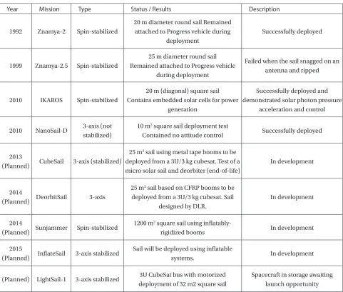
Table 1 shows a list of known solar sail demos and missions – past and future.
2. Solar Sail Fundamentals and History
he force from solar pressure comes from the momentum transfer when solar photons (light) are relected of the sail – which is made of lightweight, highly relective material. If the sail is tilted so that the force vector adds velocity to the orbital velocity of the spacecraft, then it goes faster and the orbit is enlarged. If the sail is tilted the other way so that the force vector subtracts velocity from the orbital velocity, then the spacecraft goes slower and the orbit is made smaller. hus the direction of the solar sail spacecraft can be controlled by changing the attitude of the solar sail itself. his is how a solar sail “tacks.” Flying in Earth orbit requires frequent tacking every orbit in order to track the Sun, maneuvers not required when lying in interplanetary space. For this reason most solar sail light applications are in interplanetary space – hovering between the Earth and Sun for solar weather monitoring, maintaining a ixed position for Earth or other planetary observation, and enabling rendezvous and round-trip missions to comets and asteroids.
he principle of solar sailing is succinctly stated by
ac=F/M=2Pe/c/M
where ac is the acceleration imparted to the spacecraft at 1
AU distance from the Sun, F is the force from solar photons (energy), M is the spacecraft mass. Force is the power density from solar light multiplied by the area of the sail: Pe=1370
watts/m2 x Area. From this equation the key spacecraft
design objectives immediately follow: to the extent practical, keep the mass small and the area large.
hat sunlight has energy and can provide a force has been known since the late 19th century, and the efect was observed
as a non-gravitational force perturbing the orbits of comets. But it was Frederik Tsander and Konstantin Tsiolkovsky in the Soviet Union in the 1920s who irst theorized about it providing a propulsive force for spacecraft. he irst mission application seriously studied by NASA was an extremely large solar sail to enable a rendezvous with Halley’s Comet. It was an audacious idea, before its time, but the study of the mission captured both public and technical interest and led to several smaller development eforts mostly with private funding. However, by the 1990s, several national space agencies began technology programs for solar sails.
he Russian Space Agency conducted solar sail deployments in free-standing experiments observable by astronauts from their space station. he irst Znamya in 1993 was successful; the second in 1999 collided with a deployed spacecraft antenna.
launched in Russia. he 2005 launch failed. Meanwhile JAXA began a series of deployment test lights in 2004 leading to the successful light of IKAROS in 2010.
NASA developed a sail vehicle on a CubeSat bus, NanoSail-D. It was not intended for actual solar sailing, but rather as a demonstration of a sail to act as an atmospheric drag device for deorbit. Its launch failed in 2008. A second attempt was made in 2010 using the light spare. It succeeded in its orbital deployment of the sail and reentered the atmosphere several months later.
he Planetary Society took the basic NanoSail concept and developed a fully functional sailcraft with attitude control, communications, and telemetry capability called LightSail. he spacecraft is now completely assembled and sitting in storage awaiting a launch opportunity to a suiciently high
altitude -- out of the Earth’s atmosphere where solar pressure dominates.
3. Missions Enabled by Solar Sails
[image:4.669.95.576.123.532.2]Now that the principles of solar sailing have been discussed, a range of potential mission applications can be investigated. Before speciic mission concepts are presented, the useful domain of operation of solar sails can be outlined. Traditionally, solar sailing has been seen as an eicient means of delivering science payloads to planetary bodies, small solar system bodies, or solar polar orbit. However, solar sails can also be used to enable highly non-Keplerian orbits. hese new families of orbits are extensions to the
Table 1. Known Solar Sail Demos and Missions (Past and Future)
Year Mission Type Status / Results Description
1992 Znamya-2 Spin-stabilized
20 m diameter round sail Remained attached to Progress vehicle during
deployment
Successfully deployed
1999 Znamya-2.5 Spin-stabilized
25 m diameter round sail Remained attached to Progress vehicle
during deployment
Failed when the sail snagged on an antenna and ripped
2010 IKAROS Spin-stabilized
20 m (diagonal) square sail Contains embedded solar cells for power
generation
Successfully deployed and demonstrated solar photon pressure
acceleration and control
2010 NanoSail-D 3-axis (not
stabilized)
10 m2 square sail deployment test
Contained no attitude control Successfully deployed
2013
(Planned) CubeSail 3-axis (stabilized)
25 m2 sail using metal tape booms to be
deployed from a 3U/3 kg cubesat. Test of a micro solar sail and deorbiter (end-of-life)
In development
2014
(Planned) DeorbitSail 3-axis
25 m2 sail based on CFRP booms to be
deployed from a 3U/3 kg cubesat. Sail designed by DLR.
In development
2014
(Planned) Sunjammer Spin-stabilized
1200 m2 square sail using
inlatably-rigidized booms In development
2015
(Planned) InlateSail 3-axis stabilized
Sail will be deployed using inlatable
systems. In development
(Planned) LightSail-1 3-axis stabilized 3U CubeSat bus with motorized
deployment of 32 m2 square sail
DOI:10.5139/IJASS.2012.13.4.421
424
Int’l J. of Aeronautical & Space Sci. 13(4), 421–427 (2012)
classical two and three-body problems of orbital mechanics. By exploiting the continuous low thrust available from a solar sail, exotic orbits can be found which are displaced high above the plane of the solar system, or orbits can be artiicially processed to track the motion of the Earth’s magnetic tail. In the longer term, high performance solar sails can enable fast outer solar system mission to beyond the heliopause and into true interstellar space.
3.1. Near and Mid-Term Missions
Potentially the simplest application of solar sailing, with the lowest required sail acceleration, is the GeoSail mission concept. A small solar sail with a characteristic acceleration of order 0.1 mm s–2 can be used to process a long elliptical
Earth-centered orbit to keep a science payload permanently within the Earth’s geomagnetic tail. he sail forces the orbit major axis to process at close to 1o per day so that the major
axis of the ellipse always point along the Sun-Earth line, with the orbit apogee directed away from the Sun. Since a low mass ield and particle instrument suite is typically required for geomagnetic tail missions, GeoSail can in principle be an early, low cost science application of solar sailing [7].
For a sail with a characteristic acceleration of order
0.15 mm s–2 other mission opportunities are enabled. For
example, the Geostorm mission concept uses a solar sail to station a space weather payload sunwards of the classical L1 Lagrange point close to the Sun-Earth line. he sail is
canted so that the artiicial equilibrium position is displaced both sunwards, and slight of the Sun-Earth line to ensure that the sail is away from the solar radio disk when viewed from the Earth. Being displaced sunwards of the classical L1 point the space weather payload will detect scoronal mass ejections early and so potentially doubling the warning time of impending terrestrial space weather events [8].
Other applications of solar sails in near-Earth space include exploiting artiicial equilibria high above the ecliptic plane. For a sail with a characteristic acceleration of order 0.2 mm s–2 the sail can be stationed directly over the polar
axis of the Earth at the summer solstice. An imager located at such an artiicial equilibrium position would provide a real-time, hemispherical view of high latitude regions and the poles for climate science, albeit with a low spatial resolution due to the large Earth-spacecraft distance of order 3 million km. Conventional spacecraft in polar orbit can provide high spatial resolution, but the temporal resolution of high latitude regions is typically poor since images from many polar passes need to be assembled to provide full coverage of the Arctic and Antarctic [9].
Solar sails can easily deliver payloads to close, polar
orbits about the Sun for solar physics mission applications. Payloads can be delivered by irstly spiraling inwards to a close, circular heliocentric orbit, the radius of which is limited by the thermal tolerance of the sail ilm (typically of order 0.25 AU). hen, the orbit inclination of the solar sail is cranked by turning the sail and alternately directing a component of the light pressure force above and below the orbit plane every half orbit. For example, a solar sail with a high characteristic acceleration of 1 mm s–2 can deliver
a payload to a solar polar orbit at 0.5 AU with a mission duration of only 2.5 years starting from an Earth escape trajectory [10].
Other inner solar system missions, such the delivery of payloads to Mercury ofer quite spectacular opportunities. A ballistic transfer to Mercury using conventional chemical propulsion requires an extremely large v of order 13 km s-1,
although this can be reduced using gravity assists at the expense of increased mission duration. A solar sail with a large payload mass fraction and a characteristic acceleration of 0.25 mm s-2 will deliver a payload to Mercury in only 3.5
years, while a solar sail with double the performance will require only 1.5 years. hese inner solar system missions then make optimum use of solar sailing by utilizing solar light pressure to enable extremely high-energy missions [11].
For payload delivery to Mars outward spiral times tend to be somewhat longer than for ballistic transfers. However, solar sailing is not constrained by the waiting period between ballistic launch opportunities. Again, for a large characteristic acceleration of 1 mm s-2 the trip time
to Mars is of order 400 days, with an additional 100 days required for capture to an initial highly elliptical orbit and the subsequent inward spiral to a low planetary orbit. While solar sails can in principle deliver a larger payload mass fraction than chemical propulsion, one-way Mars missions do not make optimum use of solar sailing since the required Δv is relatively modest.
Although one-way Mars missions do not appear attractive, two-way sample return missions do provide opportunities. For a ballistic mission, the mass delivered to Mars must include propellant for the return leg of the trip. For a solar sail mission however, propellant is only required for a lander to descend to and ascend from the Martian surface.
from an initial Earth parking orbit. he solar sail can then return to Earth in 2 years to be loaded with another payload for delivery to Mars. his appears to be the largest solar sail which could be reasonably delivered to Earth orbit in a single launch using a large expendable vehicle.
Due to the diminished solar radiation pressure in the outer solar system, insertion of payloads into planetary orbit must be achieved using storable chemical propulsion, or aero braking if appropriate. Payloads can be delivered to Jupiter and Saturn with minimum transfer times of 2.0 and 3.3 years respectively using a solar sail with a characteristic acceleration of 1 mm s-2. After launch to an Earth escape
trajectory the solar sail makes a loop through the inner solar system to accelerate onto a quasi-ballistic arc.
Again, due to the potentially unlimited Δv capability of solar sails, multiple small body rendezvous missions are possible, as are small body sample returns. For example, a sample return from comet Encke can be achieved with a mission duration of order 5 years, again using a sail with a characteristic acceleration of 1mm s-2. An Encke mission is
particularly diicult since the comet has a high eccentricity, requiring signiicant energy for both the rendezvous and return phase. Also of interest is the possibility of a survey of multiple asteroids. his is a particularly attractive and cost efective concept since the mission is essentially open ended, allowing repeated science returns using the same suite of instruments [12]. A solar sail with autonomous on-board navigation and planning software ofers exciting possibilities for such missions.
3.2. Far -Term Missions
he long-range goal, some might say even the raison d’être of solar sailing, is interstellar light. Sailing on light is the only technology we now have that can someday enable practical interstellar light. Sunlight will run out, even within our solar system, as an efective source of light force, but a powerful laser could focus light over interstellar distances and the resulting beamed light sail can accelerate the spacecraft to achieve interstellar missions. To achieve this goal will require a large space-based laser, presumably solar powered. Such a capability is many decades away [13].
However interstellar precursors may be possible much earlier with pure solar sail light. Using the low mass nano-spacecraft with larger sail areas and advanced sail ilm material, missions that ly in toward the Sun with a very low perihelion can achieve very high escape velocities from the solar system. Achieving missions with extra-solar system destinations hundreds of AU from the Sun may be possible in less than 50 years [14].
4. Technology Status - Small Solar Sails
With the rapid development and utilization of very small spacecraft such as cubesats, the need for innovative, lightweight propulsion systems with very high ΔV capabilities has increased commensurately. Solar sail propulsion ofers these small spacecraft increased capability, allowing propulsive-intense maneuvers to be accomplished inexpensively and with minimal accommodation requirements.
4.1. NanoSail-D
NanoSail-D is a 3U cubesat sailcraft that was successfully launched on the FastSat-1 mission on November 19, 2010 with deployment on January 17, 2011 [15]. he light phase of the mission successfully demonstrated a deorbit capability that could potentially be used to bring down decommissioned satellites and space debris by re-entering and totally burning up in the Earth's atmosphere. he stowed sails were 2.5
u CP-1 material with an area of approximately 10 m2 and
utilized 2.5 m Triangular Rollable And Collapsible (TRAC) booms. NanoSail-D re-entered the Earth’s atmosphere on September 17, 2011, after spending 240 days in space.
4.2. CubeSail
CubeSail is a nano-solar sail mission based on the 3U CubeSat standard, which is currently being designed and built at the Surrey Space Centre, University of Surrey and funded by Astrium. CubeSail will have a total mass of around 3 kg and will deploy a 5 x 5 m sail in low Earth orbit. he primary aim of the mission is to demonstrate the concept of solar sailing and end-of-life deorbiting using the sail membrane as a dragsail. he spacecraft will have a compact 3-axis stabilized attitude control system, which uses three magnetic torquers aligned with the spacecraft principle axis as well as a novel two-dimensional translation stage separating the spacecraft bus from the sail.
he CubeSail will demonstrate solar sailing by changing the inclination of its orbit. To keep the efects of drag low, the CubeSail will face towards the normal of the orbital plane, lying on its edge into the velocity vector. he initial orbit is a ~700 km sun-synchronous orbit. he inclination stays roughly the same throughout the 360 days of the simulation for the CubeSat, while the CubeSail achieves a 2o change in
DOI:10.5139/IJASS.2012.13.4.421
426
Int’l J. of Aeronautical & Space Sci. 13(4), 421–427 (2012)
4.3. DeorbitSail
DeorbitSail is a cubesat mission to demonstrate in-space deployment of a large thin membrane sail and to demonstrate deorbiting. he sail will be deployed from a 10 x 10 x 30 cm cubesat platform which will be 3-axis controlled.
he uncontrolled growth of the space debris population has to be avoided in order to enable safe operations in space for the future. Space system operators need to take measures to conserve a space debris environment with tolerable risk levels, particularly in Low Earth Orbit (LEO) altitude regions. DeorbitSail will demonstrate the use of sail deployment technology for use as a deorbiting system. he efectiveness of such deorbiting device is predicted to be high at altitudes lower than 1000 km for mini-satellites (20 to 500 kg) if deorbiting time constraints of 25 years are being considered. he same design will also be capable of using solar radiation pressure as a deorbiting force above 1000 km in altitude.
4.4. InlateSail
InlateSail will be stored in a 3U cubesat structure and the launch costs will be freely covered as part of the space technology light demonstrator mission QB50. It is to demonstrate rigidization of an inlatable structure in orbit. InlateSail is a circular sail supported by an inlatable structure that can potentially be used as a drag brake for deorbiting, as a solar sail propulsion system, as a large relector/antenna, or as a Sun shield. It is to have a total sail area of approximately 10 m2 with a 3 m diameter
inlatable torus frame that stretches the sail ilm by a series of equidistant cords. he torus is to be suspended from the satellite bus by three inlatable booms.
4.5. LightSail
LightSail-1 is being developed by the Planetary Society using entirely private funding. he 3-axis stabilized spacecraft will have a total area of 32 m2 and be deployed from a cubesat. he LightSail is designed to deploy at an altitude of 800 km and will demonstrate controlled sailing after deployment.
he LightSail spacecraft is complete and now in storage awaiting a launch.
5. Technology Status - Large Solar Sails
To implement many of the ambitious solar sailing missions described in Section 3 will require very large sails on the order of a few tenths to a half of a kilometer in diameter. Sails
in this size class are being developed and tested in Europe, Japan, and the United States.
5.1. IKAROS
IKAROS launched by JAXA on May 21, 2010. IKAROS successfully deployed on June 9, 2010. In December 2010 IKAROS successfully passed by Venus showing an accumulated acceleration of 100 m/s [3]. he spacecraft weighs approximately 300 kg and consists of four 7.5 u sail quadrants which deploy using centrifugal force to a diameter of 20 m [16]. Several unique features of IKAROS include:
• in ilm solar cells attached directly to certain areas of the membrane. hey generate almost 500W. he area ratio is 5%.
• Steering device: Variable relectance elements are loaded near the tips of the membrane. hey can be used to control the spin direction and provide attitude control.
5.2. Sunjammer
he L’Garde Sunjammer mission will see the development and light of a 1200 m2 solar sail with an anticipated launch date in 2014. he preliminary design calls for the sail to be boosted to Geostationary Transfer Orbit (GTO) as a secondary payload. Once Sunjammer (the sailcraft is named after a short story by Arthur C. Clarke) is released from the booster vehicle, it will perform a propulsive burn and boost itself to an earth escape orbit. Upon reaching this trajectory, the sail will be deployed and the demonstration mission will begin.
he Sunjammer design relies on L’Garde inlatable rigidizable technology in the sail structure. he sail structure consists of four conically-stowed, inlatably-deployed, cold-rigidized booms. hese four booms are connected at the center of the sail area to the sailcraft bus. Less than 2 days after launch, the solar sail will be deployed to full size and separated from the carrier. Within 6 days of launch the sail will be calibrated and trimmed. For the next 30 days the sail will navigate to demonstrate and fulill navigation requirements. Sunjammer will ly the sail near L1 and inally to a sub-L1 location. Along the way, an onboard magnetometer will be measuring magnetic ield and comparing the results with NOAA’s Advanced Composition Explorer. It is hoped that these measurements will foster infusion of this technology into the space weather monitoring community.
5.3. Gossamer Spacecraft Initiative
Initiative (GSI). he GSI has three parts with Gossamer-1 a small 5 x 5 m in-orbit deployment test, Gossamer-2 a 20 x 20 m in-orbit deployment test and Gossamer-3 a full solar sail demonstration of a 50 x 50 m sail. At the completion of the roadmap, the solar sail assembly would then be available for future science and commercial mission applications. Gossamer-1 will use DLR composite boom technology with the booms wound onto a spool and deployed by a drive motor. he sail ilm will use conventional 7.5 mm Kapton. Goassmer-3 is expected to deliver a characteristic acceleration of greater than 0.1 mm s-2 and will spiral to Earth escape after deployment.
6. Conclusions
Solar sail technology is advancing rapidly around the world. he Japanese IKAROS mission conirmed via light testing in deep space that large solar sail technology is viable for space light operations and NanoSail-D performed a similar function for small spacecraft. Many important applications of solar sails have been identiied as useful to the international science community and there is a growing interest in using solar sails to implement them.
References
[1] Friedman, L., Carroll, W., Goldstein, R., Jacobson, R., Kievitt, J., Landel, R., Layman, W., Marsh, E., Ploszaj, R., Rowe, W., Ruf, W., Stevens, J., Stimpson, L., Trubert, M., Varsi, G., and Wright, J., “Solar Sailing-he Concept Made Realistic”, AIAA-78-82, 16th AIAA Aerospace Sciences Meeting,
Huntsville, AL, January 1978.
[2] Johnson, L., Young, M., and Montgomery, E., “Recent
Advances in Solar Sail Propulsion Systems at NASA”, Acta
Astronautica, Vol. 61, 2007, pp. 376-382.
[3] Tsuda, Y., Mori, O., Funase, R., Sawada, H., Yamamoto, T., Saiki, T., Endo, T., Yonekura, H., and Kawaguichi, J., “Achievement Of Ikaros – Japanese Deep Space Solar Sail
Demonstration Mission”, 7th IAA Symposium On Realistic
Near-Term Advanced Scientiic Space Missions, Aosta, Italy, 2011.
[4] Cantrell, J., and Friedman, L., “Lightsail 1 – Flying for Less”, Proceedings of the Second International Symposium on Solar Sailing (ISSS 2010), New York, NY, 2010.
[5] Burton, R., Laystrom-Woodard, J., Benavides, G.,
Carroll, D., Coverstone, V., Swenson, G., Pukniel, A., Chosh, A., and Moctezuma, A., “Initial Development of
the CubeSail/UltraSail Spacecraft”, Joint Army Navy NASA
Air Force (JANNAF) Spacecraft Propulsion Subcommittee Meeting, Colorado Springs, CO, 2010.
[6] Lappas, V., Adeli, S.N., Fernandez, J., heodorou, T., Visagie, L., Steyn, W.H., Le Couls, O., and Perren, M., “CubeSail: A low cost small CubeSat mission for deorbiting
LEO objects”, Proceedings of the Second International
Symposium on Solar Sailing (ISSS 2010), New York, NY, 2010. [7] Macdonald, M., Hughes, G.W., McInnes, C.R., Lyngvi, A., Falkner, P., and Atzei, A., “GeoSail: an elegant solar sail demonstration mission”, Journal of Spacecraft and Rockets, Vol. 44, No. 4, 2007, pp. 784-796.
[8] West, J.L., “Solar sail vehicle system design for
Geostorm Warning Mission”, AIAA Space 2000 Conference
and Exposition, Long Beach, CA, 2000.
[9] Ceriotti, M., and McInnes, C., “Systems design of a hybrid sail pole-sitter”, Advances in Space Research, Vol. 48, No. 11, 2011, pp. 1754-1762.
[10] Leipold, M., Seboldt, W., Borg, E., Herrmann, A., Pabsch, A., Wagner, O., and Bruckner, J., “Mercury
Sun-Synchronous polar orbiter with a solar sail”, Acta
Astronautica, Vol. 39, 1996, pp. 143-151.
[11] Macdonald, M., McInnes, C.R., and Dachwald, B., “Heliocentric solar sail orbit transfers with locally optimal control laws”, Journal of Spacecraft and Rockets, Vol. 44, No. 1, 2007, pp. 273-276.
[12] Johnson, L., Alexander, L., Fabisinski, L., Heaton, A., Miernik, J., Stough, R., Wright, R., and Young, R., “Multiple
NEO Rendezvous Using Solar Sail Propulsion”, AIAA Global
Space Exploration Conference, Washington DC, 2012. [13] Forward, R.L., “Roundtrip Interstellar Travel Using Laser-Pushed Light Sails”, Journal of Spacecraft and Rockets, Vol. 21, 1984, pp. 187.
[14] Johnson, L., and Leifer, S., “Propulsion Options
for Interstellar Exploration”, AIAA/ASME/SAE/ASEE Joint
Propulsion Conference and Exhibit, Huntsville, AL, 2000. [15] Alhorn, D., Casas, J., Agasid, E., Adams, C., Laue, G., Kitts, C., and O’Brien, S., “NanoSail-D: he Small Satellite
hat Could”, 25th Annual AIAA/USU Conference on Small
Satellites, Ogden, UT, 2011.