Aerodynamic Separability in Tip Speed Ratio and
Separability in Wind Speed- a Comparison
M L Gala Santos1, W E Leithead2 and P Jamieson3
1 CDT Wind Energy Systems, Department of Electronic and Electrical Engineering,
University of Strathclyde. Royal College Building, room 3.36, 204 George Street, Glasgow G1 1XW, UK
2 Industrial Control Centre, Department of Electronic and Electrical Engineering,
University of Strathclyde. Royal College Building, room 2.16, 204 George Street, Glasgow G1 1XW, UK
3CDT Wind Energy Systems, Department of Electronic and Electrical Engineering. ,
University of Strathclyde. Royal College Building, room 3.36, 204 George Street, Glasgow G1 1XW, UK
E-mail: 1[email protected], 2 [email protected], 3[email protected]
Abstract. From extensive application over a number of years, it has been established that the nonlinear rotor aerodynamics of typical medium and large wind turbines exhibit an effectively global separability property, in other words the aerodynamic torque of the machine can be defined by two independent additive functions. Two versions of the separability of aerodynamic torque for variable speed wind turbines are investigated here; the separated function, related to wind speed, in the first version is only dependent on that variable and not rotor speed and in the second version is only dependent on tip speed ratio. Both provide very good approximations to the aerodynamic torque over extensive neighbourhoods of
T
0, at least from 0 to2
T
0.1. Introduction
The aerodynamic torque, T, for a wind turbine is dependent on the wind speed, V, the blade pitch angle, , and rotor speed, ; that is,
)
,
(
2 21
Q
C
ARV
T
;
R/V (1)In this paper, two different forms of separability of the aerodynamics for variable speed wind turbines are compared. The first form is purely empiric in derivation and is a direct extension of separability for a constant speed wind turbine. The second form is derived from the nature of the physical relationship (1). The paper is organised as follows. In section 2 and section 3, separability of the aerodynamics for constant speed wind turbines and for variable speed wind turbines, respectively, are discussed. In section 4, separability of the aerodynamics for variable speed wind turbines, based on empirical extension of the constant speed case, is presented. In section 5, separability of
2 2
/
)
,
(
/
C
Q
T
(2)is discussed and, in section 6, separability of the aerodynamics for variable speed wind turbines, based on the nature of this physical relationship, is presented. In section 7, the two forms of separability are discussed and, in section 8, some concluding remarks are made.
2. Constant speed wind turbines
For a constant speed wind turbine, the rotor speed is
0 and rated torque isT
0. In above rated conditions, there is a pitch angle at which rated torque is attained for each wind speed; that is, there is a locus of equilibrium operating points on which the torque isT
0. Provided ( ) is monotonic, where ( ) is the relationship of to along this locus of equilibrium points, and ( ) and( ) are chosen such that
( ) ( ( ))
(3)
( ) ( ( ) )
(4)
then, on the locus,
( ) ( ) ( ) ( ( ) ( )) (5)
Furthermore, the partial derivatives by construction are, also, correct on the locus. The relationship of ( ) to ( ) is
( ) ( ( )) ( )
(6)
( ) ( ( )) (7)
Hence, on the locus, ( ( ) ( )) .
Locally to the locus of equilibrium operating points, ( ) is a good representation of
( ), that is, within a sufficiently small neighbourhood of the locus the difference can be made
arbitrarily small. More generally, near the locus,
( ) ( ) ( ( ( ) ( ))) (8)
for any function such that,
( )|
(9)
i
( )|
(10)
By judicious choice of ( ), the size of the neighbourhood can be maximised. In effect, in a region that includes the whole set of equilibrium operating points, the dependence of aerodynamic
i
torque on pitch angle is through ( ) and on wind speed through ( ) whilst the dependence on displacement of the operating point from the locus is through [5].
Somewhat surprisingly, ( ) ( ( ( ) ( ))) applies for a large
neighbourhood for all rotors, catering satisfactorily for a very broad range of values of pitch angle and wind speed that includes all the normal operating points. Furthermore, ( ), is generally a very weak nonlinear function. Typically, the neighbourhood includes values of aerodynamic torque from 0 to
3
T
0. Indeed, it only starts to break down on the rotor entering stall.The significance of the above, particularly in the context of wind turbine control, is that the wind turbine can be viewed as a nonlinear dynamic system dependant only on the pitch angle (the nonlinearity ( )) with an additive external disturbance dependent only on wind speed ( ( )) ii[5].
[image:3.595.178.413.344.520.2]In Figure 1, the aerodynamic torque for a 3MW HAWT is plotted against its separated representation, ( ). The range of pitch angles is from 3o to 19o and wind speed from 11.41m/s to 24.21 m/s. Rated torque is 1.586×10⁶. Clearly, ( ) is a good approximation to ( ) even for operating points far from rated torque. A best fit to the data would be an appropriate choice for ( ).
Figure 1. Separability for a constant speed pitch regulated wind turbine.
3. Variable speed wind turbines
For variable speed wind turbines, separation functions, ( ), ( ) and ( ), can be determined for different values of rotor speeds, . Hence, for the locus of equilibrium operating points, i.e all operating points, (
,V,
), for which T(
,V,
) isT
0,( ) ( ( ) ( )) (11)
where ( ) and ( ) are defined by
( ) ( ) (12)
( ) ( ) (13)
ii Functions ( ) and ( ) are unique for each and rotor
-1
0
1.586
8
x 10
6-1
0
1.586
8
x 10
6T
o
rq
u
e
[N
m
]
Note, has a range of possible values, that includes rated rotor speed, , and the locus is now a 2-dimensional surface in a 4-dimensional space. In the neighbourhood of the locus of equilibrium operating points
( ) ( ( ( ) ( ))) (14)
where ( ) ( ). Consider the set of points, ( ) , on the locus, for which the aerodynamic torque has constant value, . These points can be continuously parameterised by such that
() ( () () ()) (15)
Since () () () ()
(16)
[image:4.595.79.519.307.707.2]the partial derivative with respect to is simply related to the other two partial derivatives. Since the partial derivatives with respect to and V of the separated form, ( ( ) ( )), on the locus of equilibrium points are correct by construction, the partial derivative with respect to is also correct.
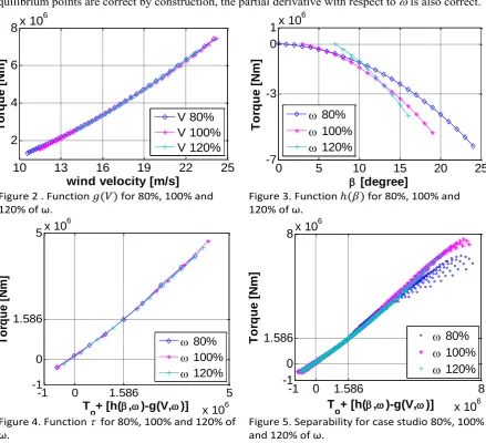
Figure 2 . Function ( ) for 80%, 100% and 120% of ω.
Figure 3. Function ( ) for 80%, 100% and 120% of ω.
Figure 4. Function for 80%, 100% and 120% of ω.
Figure 5. Separability for case studio 80%, 100% and 120% of ω.
The separated representation of the aerodynamics is determined for a variable speed HAWT with the same rotor characteristics as the constant speed HAWT in section 1. The rotor speed range is
10
13
16
19
22
25
2
4
6
8
x 10
6
wind velocity [m/s]
T
o
rq
u
e
[N
m
]
V 80%
V 100%
V 120%
0
5
10
15
20
25
-7
-3
0
1
x 10
6
[degree]
T
o
rq
u
e
[N
m
]
80%
100%
120%
-1 0 1.586 5
x 106
-1 0 1.586
5x 10
6
T
o+ [h(,)-g(V,)]
T
o
rq
u
e
[N
m
]
80%
100%
120%
-1
0
1.586
8
x 10
6-1
0
1.586
8
x 10
6
T
o
+ [h(
,
)-g(V,
)]
between 80% and 120% of rated rotor speed, . The functions, ( ) and ( ), are depicted in Figures 2 and 3, respectively, with values of 80%, 100% and 120% . The similarity of the functions, ( ), is striking. In Figure 4, the aerodynamic torque ( ), is plotted against its separated representation, ( ( ) ( )). The separated representation is again a good approximation.
4. Separability in wind speed
The observation, that the plots in Figure 2 are very similar, suggests strongly that separability could have a simplified form with ( ) only dependent on V; that is, on the locus of equilibrium operating points
( ) ( ) ( ( ) ( )) (17)
For any choice of constant rotor speed, , on the locus of equilibrium operating points,
( ) ( ) ( ) ( ) ( ) ( )
( ) ( ( )) ( ( )) ( )
( ( )) ( )
(18)
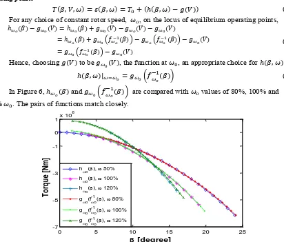
Hence, choosing ( ) to be ( ), the function at , an appropriate choice for ( ) is
( ) ( ( )) (19)
In Figure 6, ( ) and ( ( )) are compared with values of 80%, 100% and
[image:5.595.95.507.232.583.2]120% . The pairs of functions match closely.
Figure 6. Validation of simplified wind speed separability
5. Separability in tip speed ratio The aerodynamic torque is defined as
( ) ( ) ( ) (20)
where is a constant. Separability is applied to ( ) ( ) along the locus of operating points on which ( ) ( ) with such that
( ) ( ( ) ( )) (21)
0 5 10 15 20 25
-7 -5 -3 -1 0 1x 10
6
[degree]
T
o
rq
u
e
[N
m
]
ho(), 80%
h
o(), 100% ho(), 120%
go(f-1o(), 80%
g o(f
-1
o(), 100% g
o(f -1
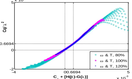
on the locus. It can be seen from Figure 7 that the separated form, ( ( ) ( )), is a good representation for ( ) for a very large neighbourhood enclosing the locus of equilibrium points. It includes values of ( ) that vary from 0 to .
Figure 7. Separabity for constant for variations of 80%, 100% and 120% of ω and
This suggests strongly that separability could have the form
( ) ( ( ( ) ( ))) (22)
on the locus of equilibrium points with ( ) . Note, the locus, on which ( ) , is different from that, on which ( ) . More generally,
( ) ( ( ( ) ( ))) (23)
for some ( ) such that ( ) and ( ) . The functions, ( ) and ( ), are determined for the separated form of ( ) using data sets for 80%, 90%, 100%, 110%, 120% and 140% for which ( ) is close to . Of course, these no longer remain local to as varies. It can be seen from Figure 8 that the separated representation, ( ( ( )
( ))), is a good representation for ( ) . The function, ( ) is also determined
independently using data sets for 80%, 100% and 120% . In Figure 9, the ( ) scaled by are shown.
Figure 8. Equilibrium points after separation Figure 9. Function ( ) scaled by 6. Comparison of the two versions of separability
In Sections 4 and 5, two different versions of separability are discussed, specifically, a separation using wind speed, (17), and a separation using tip speed ratio, (23); that is,
-4 00.6694 5
x 10-3 -2
0 0.6694
5x 10
-3
C
o + [H()-G()]
C
q/
2
& T, 80% & T, 100% & T, 120%
2 4 6 8
x 105 1
2 3 4 5 6 7 8x 10
5
T o/
2 + [H()+G()] T/
2
Equilibrium points linear fit
-1 0 1.586 7
x 106 -1
0 1.586
7x 10 6
T
o + 2
[H()+G()]
T
o
rq
u
e
[N
m
]
80%
100%
[image:6.595.87.507.527.663.2]0 5 10 15 20 25 -6
-4 -2 0
x 106
[degree] h(
,
)
10 15 20 25
2 4 6 8
x 106
V [m/s]
g
(V)
80%
100%
120% g(V) OPTIMISED
( ( ( ) ( ))) ( ( ( ) ( ))) (24)
For wind speed separability, ( ) and ( ) together with optimised polynomial fits,
( ) and
g
(
V
)
aV
2
bV
c
, are depicted in Figure 10. For tip speed [image:7.595.78.508.132.373.2]ratio separability, ( ) and ( ), together with optimised fits ( ) and ( ) ( ) , are depicted in Figure 11.
Figure 10. Wind speed separability equations Figure 11. Tip speed ratio separability equations
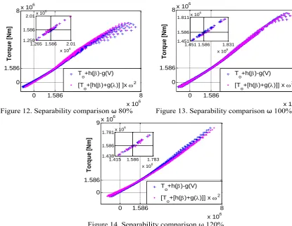
In Figures 12, Figure 13 and Figure 14 the two versions of separability are directly compared for rotor speed of 80%, 100% and 120% , respectively. Both are good approximations to the aerodynamic torque for large neighbourhoods enclosing the locus of equilibrium points. As would be expected, the 100% case exhibits the closest match. The least accurate is the 80% case but that is not unexpected since its operating points are the closest to stall.
For the tip speed ratio separability, the neighbourhood, for which the separated representation is a close approximation, extends in every case at least from 0 to , expanding as the set of operating points for the different rotor speeds move away from the stall region. It is particularly good approximation when . For wind speed separability, the neighbourhood, for which the separated representation is a close approximation, also extends in every case at least from 0 to , It is particularly good when Although there is no first principle justification for the wind speed version of separability, i.e. for a ( ) being independent of , the latter even locally to
T
0, it is at least as good as tip speed ratio separability.Each figure is further accompanied by a blow up of the data close to , i.e. the data local to the equilibrium operating points. It can be seen that there is a small inaccuracy, particularly clear in Figure 12, in the tip speed ratio version of separability. The underlying reason for this inaccuracy is the implicit assumption in Section 5 that the data sets for 80%, 90%, 100%, 110%, 120% and 140% should all lie on a straight line; that is ( ) on the operating region defined by these data sets. That this assumption is not appropriate can be seen from Figure 7 or from Figure 9.
3 4 5 6 7 8 9 10
0 1 2 3 4x 10
6
g(
)
80%
100%
120%
5 10 15 20 25
-2.5 -2 -1.5 -1 -0.5
0x 10
6
[degree]
h(
Figure 12. Separability comparison ω 80% Figure 13. Separability comparison ω 100%
Figure 14. Separability comparison ω 120%
7. Conclusion
Two versions of separability of aerodynamic torque for variable speed wind turbines are investigated; the separated function, related to wind speed, in the first version is only dependent on that variable and not on rotor speed and in the second version is only dependent on tip speed ratio. Both provide very good approximations to the aerodynamic torque over extensive neighbourhoods of , at least from 0 to . If anything, the wind speed separability is the more accurate but has the least analytic support being purely empirically motivated. The two versions of separability are illustrated by application to a 3MW HAWT.
Acknowledgments
Authors wish to thank EPSRC for their support to the project through the CDT Wind Energy Systems based at the University of Strathclyde, Glasgow, UK.
References
[1] Jamieson, P., Leithead, W.E., Gala Santos, M.L., ‘The Aerodynamic Basis of a Torque Separability Property’. Proceedings of EWEA 2011, Brussels, 2011.
[2] Leithead, W.E., Rogers, M.C.M., Agius, RR.D., ‘Dynamic analysis of the compliant tip’, University of Strathclyde, Report prepared for A.E.A. Technology, May 1992.
[3] Leithead, W.E., Rogers, M.C.M., Leith, D.J., Connor, B., ‘Design of Wind Turbine Controllers’. Proceedings of EURACO Workshop ‘Recent Results in Robust & Adaptive Control’, Florence, 1995. [4] Leithead, W., Leith, D., Harden, F., Markou, H., ‘Global gain-scheduling control for variable speed wind turbines’, (Nice, France) EWEC, 1999
[5] Leithead W.E., D.J. Leith, ‘On the Separability of Wind Turbine Rotor Aerodynamics’. Internal Report, University of Strathclyde, 2000
0 1.586 8
x 106 0
1.586 8x 10
6 T o rq u e [N m ] T
o+h()-g(V) [T
o+[h()+g()] ]x 2 1.265 1.586 2.01
x 106 1.259
1.586 2.01x 10
6
0 1.586 8
x 106 0
1.586 8x 10
6 T o rq u e [N m ] T
o+h()-g(V) [T
o+[h()+g()]] x 2 1.451 1.586 1.831
x 106 1.451
1.586 1.811x 10
6
0 1.586 8
x 106 0
1.586 9x 10
6 T o rq u e [N m ] T
o+h()-g(V) [T
o+[h()+g()]] x 2 1.415 1.586 1.783
x 106 1.438
1.586 1.781x 10
[6] Leithead, W., Harden, F., Leith, D., ‘Identification of aerodynamics and drive-train dynamics for variable speed wind turbines’, (Madrid, Spain), EWEC, July 2003.

![Figure 10. Wind speed separability equations [degree]](https://thumb-us.123doks.com/thumbv2/123dok_us/1633939.116673/7.595.78.508.132.373/figure-wind-speed-separability-equations-degree.webp)