City, University of London Institutional Repository
Citation
:
Marichal, N., Tomas-Rodriguez, M., Castillo Rivera, S. & Hernandez, A. (2012).
Modelling and Analysis of Vibrations in a UAV Helicopter with a Vision System. International
Journal of Advanced Robotic Systems, 9, p. 220. doi: 10.5772/52761
This is the published version of the paper.
This version of the publication may differ from the final published
version.
Permanent repository link:
http://openaccess.city.ac.uk/12548/
Link to published version
:
http://dx.doi.org/10.5772/52761
Copyright and reuse:
City Research Online aims to make research
outputs of City, University of London available to a wider audience.
Copyright and Moral Rights remain with the author(s) and/or copyright
holders. URLs from City Research Online may be freely distributed and
linked to.
International Journal of Advanced Robotic Systems
Modelling and Analysis of Vibrations in a UAV
Helicopter with a Vision System
Regular Paper
G. Nicolás Marichal Plasencia
1,
María Tomás Rodríguez
2,
Salvador Castillo Rivera
2and Ángela Hernández López
1,*1 Departamento de Ing. de Sistemas y Automática, Arquitectura y Tecnología de Computadoras, Universidad de La Laguna, La Laguna, Tenerife, Spain
2 The Engineering and Mathematics Department. City University, London, United Kingdom
* Corresponding author E-mail: [email protected]
Received 13 Jun 2012; Accepted 27 Aug 2012
DOI: 10.5772/52761
© 2012 Plasencia et al.; licensee InTech. This is an open access article distributed under the terms of the Creative Commons Attribution License (http://creativecommons.org/licenses/by/3.0), which permits unrestricted use, distribution, and reproduction in any medium, provided the original work is properly cited.
Abstract The analysis of the nature and damping of unwanted vibrations on Unmanned Aerial Vehicle (UAV) helicopters are important tasks when images from on‐ board vision systems are to be obtained. In this article, the authors model a UAV system, generate a range of vibrations originating in the main rotor and design a control methodology in order to damp these vibrations. The UAV is modelled using VehicleSim, the vibrations that appear on the fuselage are analysed to study their effects on the on‐board vision system by using Simmechanics software. Following this, the authors present a control method based on an Adaptive Neuro‐ Fuzzy Inference System (ANFIS) to achieve satisfactory damping results over the vision system on board.
Keywords UAV, Vibrations, Vision System, Damping
1. Introduction
The modelling and generation of vibrations in UAV helicopters are complex issues due to difficulty in the identification of the various sources, for example: the main rotor, engine, and tail rotor are common sources of undesired vibrations. In addition to this, a thorough
knowledge of the dynamical interaction existing between the main rotor and the fuselage is required in order to develop a complete and robust model that can help to control and damp these vibrations on an on‐board vision system.
Several authors have previously studied and modelled UAV’s systems. Mettler et al. described the process and results of the dynamic modelling of a model‐scaled unmanned helicopter (Yamaha R‐50 with 10ft rotor diameter) using system identification [1]. Del‐Cerro presented several modelling techniques or strategies for dynamic modelling of helicopters such as: Godbole et al. [2], Mahony et al. [3], Gavrilets et al. [4], Metler et al. [5], La Civita et al. [6], and Castillo et al. [7]. They all proposed broad approaches performed in this field. Besides this, Del‐Cerro described not only the modelling but also performed identification tasks. The proposed model was defined by using a hybrid (analytical and heuristic) algorithm [8]. El‐Saadany et al. suggested that the need for using real vehicles in the control design cycle poses a high risk and is prohibitively expensive. As a consequence of this, a real‐time simulation concept that employs cheap, practical, and rapid‐to‐build modular hardware, which can accurately simulate a real process in
the laborator integrated a
(Yamaha R‐5 into a Simuli dealt with
helicopters in development objective of
helicopter [10
The vibratio with and s comprehens small‐scale
procedure,
selection, d experimenta fully‐functio authors dea UAV helicop main rotor ( (260.5 Hz). T governed mo
Dunbabin et
challenges, c isolated visio the CSIRO a hand, the a unique and c must opera mechanical, a with broad
paper, the ra is given as: m Hz), and eng
In addition t system, land Analysis of h skid based on we can also
components
Micropilot. T phenomenon work [14].
From all the helicopters, t the system i authors carry use of Vehicl UAV dynam analysis and nature. In a vibrations ha based on an
ry environme nonlinear mo 50) with sens ink model [9]. the potentia n general as w t activities i
realising an
0].
ons in a UAV studied befo ive design m
UAV helicop which inclu design and
al evaluation onal UAV h alt with the m
pter. The thre (30.8 Hz), tai These frequen
otor speed of
t al. present onstraints, an on and sensor autonomous X authors state
challenging en ate correctly. aerodynamic
amplitude an nge of vibrati main rotor spe gine speed (160
to this, Taha
ding skid de helicopter vibr n flight data w
find docume for UAV vibr This work give n as well as a
ese contributi their modellin itself hold gr y out the mod leSim software mics provided
d study of v addition, onc
as been comp n Adaptive N
ent, is sugges odel for a sma sors, servos, a
. On the other al application well as the cur in the Nethe autonomous
V helicopter
ore; Cai et
methodology
pters. The sy uded hardw integration
‐ was used
elicopter. In main vibratio ee sources we
il rotor (143.4 ncies are estim f 1850rpm [11 ted a history nd constructio
r platform and X‐Cell helicop
that a helico nvironment in
Vibration
and from nor nd frequency
ons for autono eed (25 Hz), ta
0) Hz [12].
et al. put for esign, and vi ration and stre was given [13 ents dealing w
rations, i.e. th es an overview
starting point
ions, it can b ng and vibrat
eat interest. I delling of a U e. The detailed d in this pap
vibration´s ch ce the charac
pleted, a con Neuro‐Fuzzy
sted. The aut all scale helico
and wind mo r hand, Selier
ns of unman rrent research erlands with
unmanned m
have been d
al. presente for construc ystematic de ware compo
‐ as well
d to constru n this work,
on sources in re: rotation o 4 Hz) and en mated based
].
y of the de n of an integr d landing gea pter. On the o opter produc
which all sys sources can rmal flight mo
spectrum. In omous helicop ail rotor speed
rward an avio ibration isola ess on the lan ]. In the litera with the isola he document f w of the vibra t for experime
be seen that U tion generated In this study, UAV helicopte d modelling o
er allows for haracteristics
cterization of ntrol methodo Inference Sy
thors
opter
odels
et al.
nned
h and
the
mini‐
dealt
ed a
cting
esign
nent
l as
uct a
the
n an
f the
ngine
on a
sign,
rated
ar for
other
ces a
tems
n be
otion
this
pters
(113
onics ation. nding ature, ating from ation ental UAV
d by
, the
er by
of the
r the
and
f the
ology stem (AN dam visio The phy para Veh In s spec sect in s fina for f
2. U
Rota com fund roto veh susp allo spat turn natu fuse pass mea roto an a elev hub imp eng roto eith Figu mod The disk The prov of a UAV the
NFIS) has bee mping the unw
on system.
paper is or ysical proper ameters are p hicleSim, the s
section 4, vib ctrum is carri tion 5 and the
section 6. Seve ally section 8 c
further researc
UAV Helicopte
ary‐wing veh mposed of sev
damental are
or. The role
icle’s weight, pended in th
ws following tial direction ns. The rotor ure, are pron elage that ma
sengers’ com asurement de or of the mod articulated on vators equally b. The blades posed by the ine’s torque
or’s rotational her radians pe
(a)
ure 1. (a) Rotor’s del. Pictures take
blades can m k; this is poss first hinge (lo vides the poss attack θ). This V to climb wh other hand,
en used to
wanted distu
rganized as f ties of the
presented. Se software used ration genera ied out. The v
proposed con eral results ar contains the co
ch.
er Dynamics a
hicles ‐ usua veral subsyst the main roto of the main , to create th he air, and to g a prescribed s by changin rs of a helico ne to introd ay affect the v mfort and th
evices or visi del under cons
ne and consis y spaced and s follow a u e main rotor
applied to th l speed is rep r second or H
s lag and feather en at ULL Labo
move in and ou sible due to th ocated at a dis sibility of feath s provides th hen the angle
if the feathe
show its eff urbances appe
follows: in s helicopter
ection 3 briefl d for modeling ation and ana
vision system ntrol algorithm
re shown in s onclusions an
and Model Des
ally helicopte tems. Of the or, the fuselag n rotor is to
he lift forces
o provide the d trajectory in ng altitude an
opter, due to ducing vibrat vehicle’s perf he accuracy
ion systems
sideration in
sts of two bla d connected t uniform rotat that rotates he rotor’s hu presented by
Hz).
(b
r hinges (b) Det oratories.
ut of the plan he presence o stance d from t hering (chang he needed lift
of feather is i er angle is d
fectiveness in earing on the
ection 2, the and model’s ly introduces g this system. alysis of their m is shown in m is explained section 7 and d suggestions
scription
er‐type ‐ are ese, the most ge and the tail support the that keep it e control that n the various nd executing o its rotating tions on the formance, the of on‐board (if any). The this article is ades and two to the central ional motion s due to the ub. The main
Ω (units are
b)
tail of the UAV
ne of the rotor of the hinges. the rotor hub) ge of the angle force for the increased. On decreased, the n e e s s . r n d d s e t l e t t s g g e e d e s o l n e n e r . ) e e n e
vehicle will change of the control. This
the feather an same selected bases, at each control and
differential li moment on
paper there
This is the la blade’s root,
the blade to r is considered direction of
[image:4.595.309.538.574.698.2]blade drag fo
Figure 2. Schem
Finally, a flap an imaginary been include purposes (β
effect of the small motio convenient to been include element on th 1, the real r hinges.
On the other body section large in s systems…etc freedom are
horizontal p and rotation ψ, pitch α an
The tail rotor and spins aro
l descend ac e blade’s feath allows the ro ngle of each b d point on its
h revolution o allows for tur ift force on th the rotor. In
is a second h ag hinge, whi
reducing the b rotate on the d d to be positi rotation of t orces (see figu
matic diagram o
p hinge that al y axis perpen ed in the co
represents th e blade’s flexi ons in this d o note at this p ed in figure 2
he real rotor s rotor system
r hand, the fu n. It holds cre size, or m c., in the cas
the lateral and lane (X‐Y axi
about these sa d roll Ф degre r is mounted p ound the Y ax
ccordingly. T her angle is kn otorcraft to rise blade increase
circular pathw of the rotor, it
rns in the spa he blades that
the model un hinge after th ich provides
bending mom disk plane. Th ive when it i the rotor, as
re 2).
of the main roto
llows the blad ndicular to th omputer mod he flap angle) ibility at the
direction is r point that the
2 since it does system. As wa contains only
uselage is the ew and passe measurement
e of the UA d longitudinal is), vertical tr ame axes corr ees of freedom perpendicular xis. It has two
The simultan nown as colle e vertically. W es/decreases, a way, on indivi is known as c ace as it creat t induce a tur nder study in he feathering
stress‐relief a ments and allow
he lagging ang is opposite to
produced by
or’s hub and hin
de to rotate aro he rotor hub del for simula
. In this way root by allow reproduced.
flap hinge ha s not represen as shown in fi y feather and
e rotorcraft’s m engers or carg
devices, v V. Its degree l translation in ranslation (Z
responding to
m.
r to the main r blades, which
neous
ctive
When
at the
idual
cyclic
tes a
rning
n this
one.
t the
wing
gle, ξ,
o the
y the
nges.
ound
b has
ation
y, the
wing
It is
s not
nt an
igure
d lag
main
go if
ision
es of
n the
axis)
yaw
rotor
h are
equ The roto seco The hub from add This blad as: whe coef and aero inclu rota roto blad dire dyn
δ3 is
This and The figu dire dire Lag The 1. T out Fus Ma Ele Tai Ver Ma Tai Ma Tai Tabl The mod this mod
ally spaced a blades follow or’s rotational
ond or Hz). blades of the b by hinges. T m the tail rot dition to this,
s is a kinema de’s feather a
ere θ is feather fficient. It pla
the handlin oelastic stabil uded in the t ate around an
or hub. Theref de’s flexibility ection. From
namical coupli
s usually a sta s dynamical
steady state f real model s ure 1.b). Its p
ectly from the ect experimen una Universit measured/ob These are the
in this work. Param selage Mass
ain Rotor Blade
evator Mass
il Rotor Blade M rtical distance fu ain Rotor Blade
il Rotor Blade le ain Rotor Angul il Rotor Angula le 1. Calibre 3 p
values indica del developed
work. The n deling process
nd connected w a uniform
speed is repr
e tail rotor are The first hing
tor hub) allo feather‐flap d atic feedback
angle that is
Δθ =
r angle and k
ays an import ng qualities o ity of the bl tail rotor in o imaginary ax fore, we can r y at the root b (1) it is clear ing on the feat
Δθ = ‐ ta
andard value
coupling help flapping relati studied in thi parameters h e manufactur ntal measurem ty) facilities.
btained param values used f
meters
Mass
Mass
uselage‐main ro length
ength
lar Speed
r Speed
parameter’s valu
ated in table 1 d in VehicleSim next section c s.
d to the fusela rotational mo resented by Ω
e also connect ge (located at
ows featherin dynamical cou
of the flap a mathematica
‐ k β
is the feather‐
tant role in f of the vehicle
ade. A flap
order to allow xis perpendicu reproduce the by allowing m r to see the
ther angle:
an (δ3) β
chosen as 45o
ps to reduce
ive to the shaf is work is a C have been ob
rer’s manual
ments taken
meters are indi for the simula
Symbol V Mf
Mb Mel Mt
otor h
l
lt
Ω Ωt
ues.
1 will be intro m, the softwar
contains the d
age by a hub. otion. The tail
Ωt (radians per
ted to the tail a distance dt
ng motion. In upling exists. angle into the ally described
(1)
‐flap coupling flight stability e, as well as hinge is also w the blade to ular to the tail e effect of the motion in this effect of this
(2)
o (0.785 rads).
the transient t.
Calibre 3 (see btained either of use or by at ULL (La
icated in table ations carried
Value 2.428 (kg)
0.121 (kg)
0.041 (kg)
0.00441 (kg)
0.105 (m)
0.55 (m)
0.08 (m)
177.93 (rad/s) 889.65 (rad/s)
3. Modelling Tool: VehicleSim
VehicleSim is multibody modelling software. The system
has been used over a wide range of mechanical dynamic
problems, mainly in connection with vehicle dynamics
([16], [17], [18]) and it has provided the basis for
commercial simulation codes such as TruckSim, CarSim
and BikeSim [15]. The syntactic rules of VehicleSim are
straightforward. The output from VehicleSim can take
one of several forms: (a) a Rich Text Format file
containing the symbolic equations of motion of the
system described; (b) a”C” language simulation program
with appropriate data files containing parameter values
and simulation run control parameters or (c) linear state‐
space equations in a MATLAB ”M‐file” format that
contains symbolic state‐space A, B, C, D matrices that can
be used for linear analysis.
Once the model has been built, it becomes independent of
VehicleSim and can be executed at any time. The
multibody basis of VehicleSim is Kane’s equations, which
is an alternative statement of the Newton‐ Euler‐Jordan
(virtual power) principle. It has been proven that with
this method, fewer operations are needed to derive
equations of motion, compared with the well known
Lagrange’s energy‐based method that can only
accommodate holonomic constraints and introduces
many cancelling terms in the computations.
4. Vibration and Analysis
The complete dynamical helicopter model was
implemented as described in section 2 using the
parameters indicated in Table 1. It is assumed that the
engine regime is 1700 rpm (revolution per minute). The
fuselage has 6 degrees of freedom: longitudinal, lateral
and vertical along the axes X, Y, Z respectively and the
corresponding rotations about these same axes. The
acceleration of gravity in these simulations is neglected
(VehicleSim allows for switching off the gravity) as the
purpose of these simulations is to analyse the forces and
accelerations that appear as a result of interactions and
couplings between the various UAV components only.
In order to study the characteristics of the vibrations
appearing in the fuselage due to the main rotor only, a
simulation is carried out where the main rotor has an
angular velocity of Ω=177.9 rad/s, and the tail rotor speed
is Ωt=0rad/s. As the main objective at this stage is
vibration generation, a mass imbalance can be introduced
artificially in order to produce vibrations, i.e. the mass of
the second blade (main rotor) is set to be the double of the
other blade’s masses (Mb2=0.282kg). The vibrations that
appear will be transmitted to the fuselage.
The vibrations appearing along the fuselage’s X and Z
axis are shown for VehicleSim simulations carried out for
a duration of 5 seconds. The output of the simulation
(time history of the position, velocities and accelerations
on the fuselage) were obtained, stored in the workspace
and analysed using a FFT (Fast Fourier Transform)
Matlab algorithm. It was found that the main frequency
component of the spectrum of vibration appearing on the
fuselage’s X‐axis is f=28.32Hz, (177.93rad/s) (see figure 3).
Figure 3. Frequency and Amplitude of vibrations appearing on
the fuselage’s longitudinal axis (X).
It is evident that the main peak of frequencies is around
28.32Hz. This is caused by the main rotors blade’s mass
imbalance. In fact these results follow theoretical
predictions [11], [12].
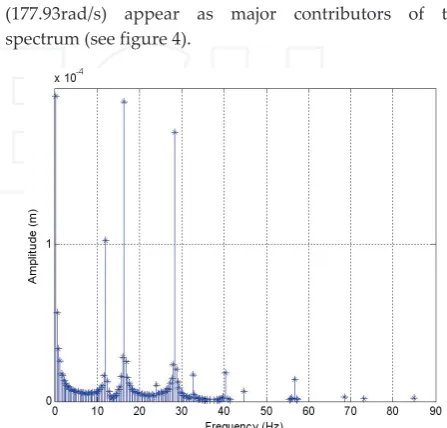
In the same way, if the spectrum of vibrations appearing
on the fuselage’s vertical direction (Z axis) is analysed,
frequencies of 16.36Hz (102.79rad/s) and 28.32Hz
(177.93rad/s) appear as major contributors of the
spectrum (see figure 4).
Figure 4. Frequency and Amplitude of vibrations appearing on
the fuselage’s vertical axis (Z).
Two peaks of frequencies appear and their amplitudes
are of similar ranges. The source of the vibration
[image:5.595.298.523.175.358.2] [image:5.595.305.529.493.707.2]characterised by the dominant frequency is the steady
load of the system, i.e. the tail rotor and the fuselage
shapes and configurations. The secondary peak in this
case is caused by the main rotor and its mass imbalance,
as it was in the case of the longitudinal vibrations (figure
3). The ranges of peak frequencies detected in these
simulations will be used later in the following sections, in
order to design a control algorithm that will isolate the
vision system from these unwanted disturbances at the
indicated frequencies.
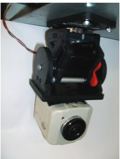
5. Vision System
Studying the effect of the vibrations produced by the
helicopter on an on‐board vision system is one of the
aims of this work. With the purpose of analysing the
behaviour of a camera if it is subjected to different
disturbances, a vision system consists of a dynamic
platform SPT 200 SERVICITY and a camera, all modelled
in Simulink/Simmechanics [19]. This platform has three
bodies separated by servomotors, providing two degrees
of freedom to the system, such as yaw and pitch angles.
The first body is the base that is fixed to the fuselage and
the camera is placed over the third body as can be seen in
Figure (5).
Figure 5. Vision system consisting of the dynamic platform with
the camera.
The Inertia matrices and other geometric parameters of
each body were calculated and subsequently introduced
in the simulation platform. The simulation developed in
Simulink/Simmechanics includes the camera, the
dynamic platform modelled with elements that simulate
its flexibility, as well as the servomotors and a PID
controller for each joint. Furthermore, two input blocks
for the vibration are put in the simulation environment
since the aim of this modelling is to analyse the camera
undesired movement if the fuselage is transmitting
vibrations. Specifically, the effects of the helicopter
vibration of the gravity axis (Y) and a perpendicular axis
(Z) are studied.
6. Control Algorithm
The chosen isolation method used to reduce the vibration
suffered by the camera is a spring‐damper system with a
variable damping value C(t). The fact that the damping
value is time‐dependant makes possible an adaptive
control with the capability of changing according to the
vibration received from the helicopter. The change of the
damping variable is provided by an intelligent system
designed to give the most adequate C value for each case.
In this work, the parameters to be considered are the
vibration frequencies. In other words, the adaptive
control system analyses the frequencies of the disturbance
produced by the helicopter in two axes and decides the
best C value for each time interval.
Due to these dependencies, it is necessary to create a
table where the more suitable damping value is
provided according to the frequencies fy and fz. From
now on, this table will be known as “reference table”.
In order to fill this table, an iterative process is carried
out whereby the C value is modified for each
combination of fy and fz. A criterion function was
defined with the purpose of deciding the most
appropriate damping value for each case. This function
is such that the camera displacement around the
equilibrium position was as low as possible.
Particularly, the standard deviation evaluates these
undesired camera movements. In this way, the
damping value that minimises the camera vibration for
each combination of frequencies is chosen. Therefore,
once the iterative process has been concluded, the
reference table is built as a result of the minimization
process of the criterion function. It allows finding the
most suitable C value corresponding to a particular
combination of the frequencies fy and fz.
The next step is to design an intelligent system capable
of providing the C value for each case based on the
reference table. Because of this, a method based on
training is necessary. Therefore an artificially
intelligent system is chosen. An Adaptive Neuro‐
Fuzzy Inference System (ANFIS) [20] has been used.
This method has neuro‐adaptative learning, that is to
say, it works similarly to neural networks, using a
given input/output data set. Specifically, in this work
the input data set is [fy fz] and its corresponding output
[image:6.595.74.272.384.647.2]
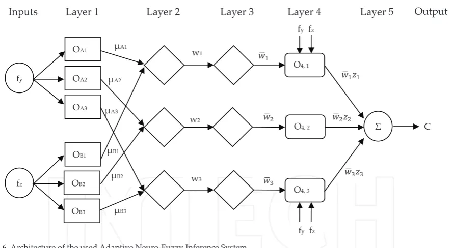
Figure 6. Architecture of the used Adaptive Neuro‐Fuzzy Inference System.
The ANFIS architecture is shown in Figure 6. It consists of
five layers with two inputs, each one with three
membership functions μAi y μBi (i=1, 2, 3), respectively,
and an output C.
The first step is to choose the number and type the
membership functions (MF) for each input and to
determine their membership degree values. In this way,
two inputs and three Generalized Bell MF were chosen
for each input. In the first layer each node has an output
defined as:
���� ������� (3) ���� �������� � � �� �� � (4)
In the second layer the fuzzy operator is applied,
therefore the input signals are multiplied and the result
represents the weight of each rule.
��� ��������������� � � �� �� � (5)
The Implication method is applied in the third layer and
the output of each node corresponds to the standard
weights, which is a number between 0 and 1.
����∑�����
��� , i= 1,…n (6)
The aggregation is presented in the fourth layer and
consists of the fuzzy sets that represent the outputs of
each rule combined into a single fuzzy set.
����� ����� � � �� �� � (7)
Where �� corresponds to three fuzzy if‐then rules of
Takagi‐Sugeno type which are:
If fy is μA1 and fz is μB1 then z1= p1fy + q1 fz + r1 (8a) If fy is μA2 and fz is μB2 then z2= p2fy + q2 fz + r2 (8b) If fy is μA3 and fz is μB3 then z3= p3fy + q3 fz + r3 (8c)
Where ��� ��� �� are the consequent parameters.
Finally, the fifth layer applies the defuzzification process.
That is, it adds all outputs of the fourth layer and gives as
output a real number corresponding to damping value. In
this paper, this process is done by a weighted average as
follows:
C =∑N������Z�
∑N������ (9)
Where C is the damping value given as system output, zi
is the output level of each rule; wi is the weight of each
rule weighted and N the total number of nodes at layer 3.
To summarise, the process of building an ANFIS model
has three phases: collecting the input/output data set that
will be used by ANFIS for training, the creation of a
Fuzzy Inference System as an initial structure [21, 22] and
finally the application of a learning algorithm
(backpropagation gradient).
The reference table, obtained with the iterative process
explained previously, is the necessary data set in order to
start the training phase. This input/output set is divided
into two groups, where eighty percent of them are used
in the ANFIS training and the remaining twenty percent
is kept back in order to test if the system has achieved the
adequate degree of generalisation.
C
��� �����
w3
μB3 μA3
OA1
fy
fz
μA1
μA2
μB1
μB2
OA2
OB1
OB2
w1
w2
Σ ���
���
fy fz
fy fz
�����
�����
O4, 1
Layer
1
Layer
2
Layer
3
Layer
4
Layer
5
O4, 2
Inputs
Output
OA3
OB3
O4, 3
[image:7.595.80.525.79.323.2]Once the ANFIS system has been trained, it is included in
the simulation environment as a Simulink block. As this
block needs the frequencies fy and fz as inputs, a method
that calculates them from the vibration signals is
required. A FFT block is added between the vibration
produced by the helicopter and the ANFIS in the Y and Z
axis. These blocks are in charge of obtaining the spectral
composition of the signal on each axe applying the Fast
Fourier Transform at intervals of 0.5 seconds. When the
ANFIS analyses the input frequencies, it provides the best
C value every 0.5s. In this way, the damping value
provided is introduced into the semi‐active control
system that is placed between the fuselage and the base of
the dynamic platform.
7. Results
With the semi‐active isolation system and the ANFIS
controller added to the simulation environment, the
vibrations from the helicopter are introduced by two
blocks: one for each axe. The following step is to analyse
the camera behaviour subjected to these vibrations and to
test the validity of the proposed control technique. The
vibrations produced by the fuselage over the X axe and Z
axe are shown in Figures 7 and 8 respectively. It is
necessary to point out that these vibrations are obtained
by the helicopter simulation platform.
Figure 7. Vibration from fuselage over the X axe.
Figure 8. Fuselage vibration over the Z axe.
Once the signals have been introduced in the simulation,
the next step is to analyse the camera behaviour. Firstly,
we measure the camera movement under the influence of
the vibrations when there is no isolation system fitted.
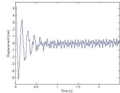
Figure 9 shows this behaviour over the gravity axe Z. As
could be observed, the camera suffers an abrupt
movement during the first half second reaching 5mm of
amplitude and after this, the camera maintains a residual
vibration of about 0.5mm. Observing this result, the need
for including an isolation system to reduce these
vibrations and to achieve a more stable vision system is
clear.
Figure 9. Camera vibration over the Z axe without isolation
system.
The proposed method based on ANFIS was used taking
into account the vibrations shown in Figures 7 and 8. As
was explained previously, the system calculates the
frequencies on each axe at each 0.5s and depending on
these values, the ANFIS gives the most adequate
damping value C. In Figure 10 we observe the dominant
frequencies obtained by the FFT block in the Z axe.
Figure 10. Dominant frequencies in Z axe.
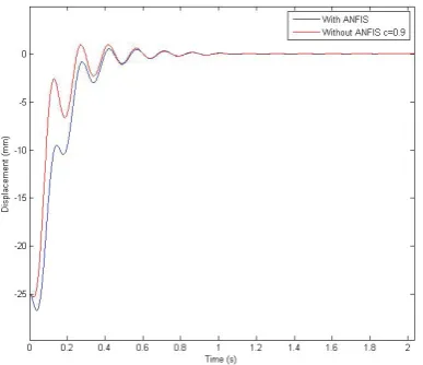
With the purpose of checking the efficiency of the
proposed method, the obtained results are compared
with a passive damping case. That is to say, the vibration
suffered by the camera with the semi‐active method
[image:8.595.318.513.246.398.2] [image:8.595.72.263.421.753.2]comparison is shown in Figure 11. It is observed that the
method with the damping value constant shows worse
behaviour during the first half second than the C variable
technique. The ANFIS method reduces the undesirable
movement of the camera in the first ten seconds. After
elapsing 1 second, both techniques are stabilised and
keep the camera vibration near zero.
[image:9.595.75.269.183.350.2]Figure 11. Comparison of the camera movement with the proposed ANFIS technique and with passive method.
8. Conclusion
A UAV helicopter was modelled in VehicleSim and used
to obtain the vibration produced by the main rotor on its
fuselage. An on‐board vision system fitted on the
fuselage will suffer the effects of these unwanted
vibrations unless a control system is applied in order to
damp those. The results presented here allow knowing
the level of vibration that will affect the vision system.
The knowledge of the predominant frequencies allows
the training of an intelligent control that will adapt itself
depending on the values of these frequencies and will
provide the adequate damping value for each situation.
The trained isolation device is introduced into the
Simulink platform with the vision system composed by
the dynamic platform and the camera. Therefore, when
the vibrations produced on the fuselage are introduced
into the simulation, it is possible to observe and to
analyse the camera behaviour under the effect of these
vibrations.
The simulations carried out show that the proposed
method based on a semi‐active device with the damping
value provided by an ANFIS improves the camera
behaviour. This improvement allows clearer images to be
obtained.
9. Acknowledgements
This work has been supported by the Spanish
Government project DPI2010‐20751‐C02‐02 of Ministerio
de Ciencia e Innovación and by the grant of the Agencia
Canaria de Investigación, Innovación y Sociedad de la
Información del Gobierno de Canarias, cofinanced with
the European Social fund.
10. References
[1] B. Mettler, T. Kanade, M.B. Tischler. “System
Identification Modelling of a Model‐Scale
Helicopter”. CMU‐RI‐TR‐00‐03
[2] D.N. Godbole et al. “Active Multi‐Model Control for
Dynamic maneuver Optimization of Unmanned Air
Vehicles.” (2000). Proceedings of the 2000 IEEE
International conference on Robotics and
Automation. San Francisco, CA. April.
[3] R. Mahony and R. Lozano. “Control for an
Autonomous helicopter in Hover Manoeuvres”.
(2000). Exact Path Tracking. Proceedings of the 2000
IEEE International Conference on Robotics &
Automation. San Francisco, CA. APRIL. P. 1245‐1250
[4] V. Gavrilets, E. Frazzoli, B. Mettler. “Aggressive
Maneuvering of Small Autonomous Helicopters: A.
Human Centered Approach” (2001). The
International Journal of Robotics Research. Vol 20, Nº
10, October. pp 795‐807
[5] B.F. Mettler, M.B. Tischler, T. Kanade. “System
Identification Modeling of a Model‐Scale
Helicopter”. (2000). T. Journal of the American
Helicopter Society. 47/1: p. 50‐63
[6] M. La Civita, W. Messner, T. Kanade. “Modeling of
Small‐Scale Helicopters with Integrated First‐
Principles and System‐Identification Techniques”.
(2002). American Helicopter Society 58th Annual
Forum, Montreal, Canada, June 11‐13
[7] P. Castillo, R. Lozano, A. Dzul. “Modeling and
Control of Mini‐Flying Machines”. 2005. Springer
Verlag London Limited. ISBN: 1852339578
[8] J. Del‐Cerro. A. Barrientos, A. Martinez. “Modeling
and Control Prototyping of Unmanned Helicopters”.
Universidad Politécnica de Madrid. Robotics and
Cybernetics Group. Spain
[9] A. El‐Saadany, A. Medhat, Y. Z. Elhalwagy. “Flight
Simulation Model for Small Scaled Rotor Craft‐Based
UAV”. 2009. 13th International Conference on
Aerospace Sciences & Aviation Technology. Asat‐13.
May 26‐28. Paper: Asat‐13‐CT‐31
[10] M. Selier and G. Voorsluijs. “Future Surveillance
Using Autonomous Unmanned Helicopters”. 2003.
American Institute of Aeronautics and Astronautics.
[11] G. Cai, L. Feng, B.M. Chen, T.H. Lee. “Systematic
Design Methodology and Construction of UAV
Helicopters”. 2008. Mechatronics, 18, 545‐558
[12] M. Dunbabin, S. Brosnan, J. Roberts, P. Coke.
“Vibration Isolation for Autonomous Helicopter
Flight”. 2004. International Conference on Robotics &
Automation. 0‐7803‐8232‐3/04, IEEE. New Orleans,
April
[13] Z. Taha, K.C. Yap, Y. Tang. “Avionics Box for a Small
Unmanned Helicopter”. 2008. Proceedings of the 9th
Asia Pacific Industrial Engineering & Management
Systems Conference. Indonesia. December 3rd ‐5th
[14] Micro Pilot. Newsletter. World Leader. Miniature
UAV Autopilots. ISO9001:2000
[15]
Available http://www.carsim.com[16] M. W. Sayers (1999) Vehicle models for RTS
applications. Vehicle System Dynamics 32(4‐5): 421‐
438
[17] R.S. Sharp, Evangelou S and Limebeer DJN,
Multibody aspects of motorcycle modeling with
special reference to Autosim, Advances in
Computational Multibody Systems, J. G. Ambrósio
(Ed.), Springer‐ Verlag, Dordrecht, The Netherlands,
2005, 45‐68
[18] M.Tomás‐Rodríguez, R Sharp, Automated Modeling
of Rotorcraft Dynamics with Special Reference to
Autosim, Automation Science and Engineering, 2007.
CASE 2007. IEEE International Conference, 2007
[19] Available:
http://www.mathworks.com/products/simulink/
[20] J.R. Jang. ANFIS: Adaptive‐network‐based fuzzy
inference system. IEEE Trans. Syst. Man Cybern.
1993, 23, 665‐685
[21] M. Guijarro, G. Pajares. On combining classifiers
through a fuzzy Multicriteria Decision Making
Approach: applied to natural textured images. Expert
Syst. Appl. 2009, 36, 7262‐7269.
[22] L.A Zadeh. Knowledge representation in fuzzy logic.
IEEE Trans. Knowl. Data Engin. 1989, 1, 89‐100.