City, University of London Institutional Repository
Citation
:
Kouris, L.A.S. and Kappos, A.J. (2012). Detailed and simplified non-linear models for timber-framed masonry structures. JOURNAL OF CULTURAL HERITAGE, 13(1), pp. 47-58. doi: 10.1016/j.culher.2011.05.009This is the accepted version of the paper.
This version of the publication may differ from the final published
version.
Permanent repository link:
http://openaccess.city.ac.uk/3562/Link to published version
:
http://dx.doi.org/10.1016/j.culher.2011.05.009Copyright and reuse:
City Research Online aims to make research
outputs of City, University of London available to a wider audience.
Copyright and Moral Rights remain with the author(s) and/or copyright
holders. URLs from City Research Online may be freely distributed and
linked to.
3 4 5 6 7 8 9 10 11 12 13 14 15 16 17 18 19 20 21 22 23 24 25 26 27 28 29 30 31 32 33 34 35 36 37 38 39 40 41 42 43 44 45 46 47 48 49 50 51 52 53 54 55 56 57 58
Detailed and simplified non-linear models
for timber-framed masonry structures
Leonidas Alexandros S. Kouris1, Andreas J. Kappos2*
1 - Doctoral Candidate, Aristotle University of Thessaloniki, Department of Civil Engineering, Division of Structural Engineering, University Campus, GR-541 24, Greece, tel: +30 2310995662, fax: +30 2310995614, email: [email protected].
2 - Professor, Aristotle University of Thessaloniki, Department of Civil Engineering, Division of Structural Engineering, University Campus, GR-541 24, Greece, tel: +30 2310995743, fax: +30 2310995614, email: [email protected].
Abstract
6 7 8 9 10 11 12 13 14 15 16 17 18 19 20 21 22 23 24 25 26 27 28 29 30 31 32 33 34 35 36 37 38 39 40 41 42 43 44 45 46 47 48 49 50 51 52 53 54 55 56 57
masonry is made here using a plasticity model. Nonlinear laws for the materials, such as a trilinear stress-strain curve for monotonic loading of timber and a Mohr-Coulomb contact law for wooden members, are used to express their behaviour under moderate and high stress levels. An associated flow rule is assumed and Hill's yield criterion is adopted with isotropic work-hardening. Masonry infills are not included in the model due to their insignificant contribution after the initial elastic stage of the response. The proposed finite element model is intended for a detailed non-linear static analysis of parts of a building. A simplified model using beam and link elements with non-linear axial springs is also developed, which is appropriate for 2-D non-linear analysis of common buildings. Both models are validated using experimental results of three T-F masonry walls obtained from the literature. Finally a non-linear static analysis of the façade of an existing building situated in the island of Lefkas, Greece is performed.
Keywords: Timber-framed masonry, seismic performance, nonlinear analysis, plasticity model, non-linear hinges.
1. Introduction
6 7 8 9 10 11 12 13 14 15 16 17 18 19 20 21 22 23 24 25 26 27 28 29 30 31 32 33 34 35 36 37 38 39 40 41 42 43 44 45 46 47 48 49 50 51 52 53 54 55 56 57 58
resisting bending moments [1, 2], while others consider timber diagonals as axially loaded bars pinned at their ends [3, 4], or a combination of these [5]. Elastic analysis is a useful tool for identifying regions with high stresses, but often fails to capture the final failure mechanism, that may be substantially affected by stress redistribution. The work presented here involves a plasticity-based finite element model for the analysis of T-F masonry structures . The proposed model is applied to the analysis of three T-F masonry walls for which experimental data are available.
Unreinforced masonry suffers from low tensile strength and low ductility. Strengthening of masonry structures against earthquakes dates from the ancient times. A technique put forward was the use of T-F masonry which has been utilised even in the Bronze Age in Greece [6-8] and in the early Roman Times [9] in regions of high seismicity. Their presence and development is closely related to earthquakes.
6 7 8 9 10 11 12 13 14 15 16 17 18 19 20 21 22 23 24 25 26 27 28 29 30 31 32 33 34 35 36 37 38 39 40 41 42 43 44 45 46 47 48 49 50 51 52 53 54 55 56 57
ties; however, these elements are usually very deficient due to their rather low resistance to corrosion.
The developed planar finite element model of T-F masonry is intended for panels and walls. An important factor in the performance of the walls is the presence of weak, rather than strong, mortar. This compensates for the incompatibility between rigid masonry panels and the flexible timber frame. The low-stiffness mortar can accommodate deformation along the bed/head joints, leading to sliding instead of cracking through the masonry units when the masonry panels are subjected to horizontal displacements. This behaviour is quite different from that of masonry infills effectively connected to the surrounding frame (a rather common case in masonry-infilled reinforced concrete frames) which would initially attract a substantial amount of the lateral (seismic) force and dissipate significant energy, but subsequently suffer significant strength and stiffness degradation due to their low deformability. Thus, T-F masonry buildings can effectively resist moderate-to-strong earthquakes, albeit with some cracking; this performance during an earthquake is manifested by the cracks at the interface between bricks and wooden frame that could lead to crushing of the brick infill at the corners of the wooden frame. This type of failure has often occurred in these buildings during recent earthquakes. Detailed descriptions of damage in T-F masonry structures during earthquakes that occurred in the past decade are given in the literature e.g. [2, 10-14].
6 7 8 9 10 11 12 13 14 15 16 17 18 19 20 21 22 23 24 25 26 27 28 29 30 31 32 33 34 35 36 37 38 39 40 41 42 43 44 45 46 47 48 49 50 51 52 53 54 55 56 57 58
they prevent timber braces from buckling. This treatment of masonry infills is in line with previous studies [3] and its main ramification is that it leads to lower stiffness during the elastic range of the response when all structural components are in some form of contact. As the lateral loading increases, and given the low efficiency of the metal joints, the infills gradually separate from the surrounding timber members and their contribution to the lateral load capacity becomes negligible. Masonry infills could be included in the analysis through proper interface models [4], but given that the present study focuses on the post-elastic behaviour of T-F masonry structures, wherein disengagement from the timber frame has already occurred, the accuracy resulting from this refinement of the model is not deemed to counterbalance the substantial increase in complexity and computational cost.
Due to their directional properties, the wooden elements can be accurately modelled as an orthotropic material. In traditional structures their mechanical parameters are difficult to determine and have a significant variability, mainly due to varying degrees of deterioration. The values adopted in the examples presented here refer to pine timber according to ΕΝ338 [15]. An appropriate interface model is adopted for the description of contact between timber braces and posts; an asymmetric contact element is chosen for the modelling of the interface. The proposed model is validated against the results of laboratory tests performed at LNEC, Lisbon [16]. These specimens are modelled using the ANSYS finite element package [17] according to the proposed method.
2. Brief overview of the history of timber-framed masonry
6 7 8 9 10 11 12 13 14 15 16 17 18 19 20 21 22 23 24 25 26 27 28 29 30 31 32 33 34 35 36 37 38 39 40 41 42 43 44 45 46 47 48 49 50 51 52 53 54 55 56 57
This type of structure was occasionally used (as a rule, not throughout the building) in Minoan Crete [6], Mycenae [8] and the island of Thera [7]. All these areas are of high seismicity, moreover the island of Thera was an active volcano at that time. Wooden framework techniques often have simple technology and are more commonly used in multi-storey structures. A few horizontal and/or vertical timber members were embodied into rubble-stone walls (Fig. 2). Timber reinforcements within masonry walls are only found in critical parts of the building. Sometimes, horizontal timber components were also embedded at the top of the masonry walls joining them at the corners. They were able to supply sufficient tensile strength to resist forces which might separate intersecting walls, acting like a tie-beam. This anti-seismic measure is found in Knossos, Tylissos, Phaistos, and elsewhere in Minoan Crete [6]. The complete T-F masonry system, consisting of horizontal beams and vertical posts, is found in a few cases of multistorey buildings in the town of Akrotiri in Thera. The 7m-high remains of the 3-storey building 'Xeste-2' is a typical example of T-F masonry formed by ordinary wooden frames with masonry infill.
6 7 8 9 10 11 12 13 14 15 16 17 18 19 20 21 22 23 24 25 26 27 28 29 30 31 32 33 34 35 36 37 38 39 40 41 42 43 44 45 46 47 48 49 50 51 52 53 54 55 56 57 58
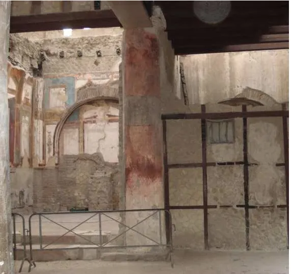
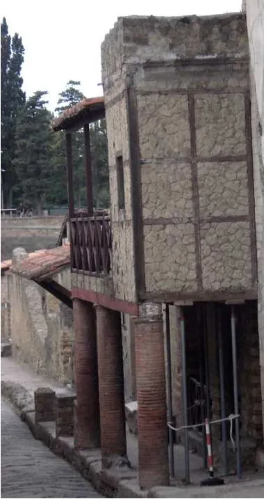
F walls are used in parts of the building as partition (non-structural) walls of the ground or the upper floors such as the building 'Hall of the Augustals' (Fig. 3a). However, the 'Trellis House' of Herculaneum (Fig. 3b), a two-storey boarding house, is built almost entirely in T-F masonry. There are also a few other similar cases in Herculaneum where T-F masonry walls are load-bearing parts of the primary structural system.
T-F masonry was extensively used during the Middle Ages. Horizontal timber elements embedded in masonry walls to enhance their ductility were commonly used in Byzantine churches in Macedonia (Northern Greece), and elsewhere [2, 18], defence walls (like the Theodosian Walls of Constantinople 408-413 AD, see Fig. 4), large edifices [19], monasteries [20] and other large structures, often covered by the characteristic red tile forming zones of stones. T-F masonry is also predominant in European countries where seismic resistance is not a key issue, for instance the late Middle Age Tudor architectural style in Britain and elsewhere in Europe (e.g. Germany, Netherlands, Nordic Countries etc.).
6 7 8 9 10 11 12 13 14 15 16 17 18 19 20 21 22 23 24 25 26 27 28 29 30 31 32 33 34 35 36 37 38 39 40 41 42 43 44 45 46 47 48 49 50 51 52 53 54 55 56 57
diagonal braces invisible from the outside, and the external masonry wall. This was a dual system with the wooden frame and the exterior unreinforced masonry walls connected to each other through metal joints.
Another timber-framed masonry system is found in Lefkas, Greece, wherein the dual system consists of the stone-masonry-built ground storey and the timber-framed upper storeys [2, 20, 22]. The upper storeys are supported by the stone-masonry ground floor but in case of its failure a secondary supporting system of timber columns is activated. These columns are either fixed to the masonry foundation or more usually free-standing, and they are not visible from the exterior. These two systems are initially joined together. This dual system was also established to resist the frequent earthquakes (Lefkas is located in the highest seismic zone of Greece).
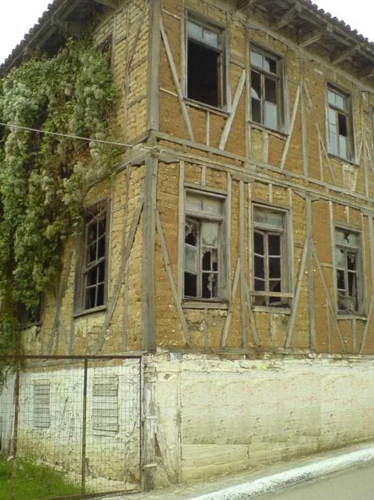
Many heritage buildings constructed in T-F masonry, without a dual system but with diagonals throughout the floors, exist in Macedonia (Fig. 1a) and in the settlement of Eressos in Lesvos, Greece [23].
Nowadays, many heritage buildings of T-F masonry located in seismic hazard areas are used as dwellings or for public services. Some of them are found in Greece, Portugal, and also in other countries like Turkey [24], India [14] etc. These structures are part of the cultural heritage and the proper assessment of their seismic vulnerability through advanced and reliable tools like non-linear analysis is certainly worthwhile.
3. Seismic behaviour of timber-framed buildings
6 7 8 9 10 11 12 13 14 15 16 17 18 19 20 21 22 23 24 25 26 27 28 29 30 31 32 33 34 35 36 37 38 39 40 41 42 43 44 45 46 47 48 49 50 51 52 53 54 55 56 57 58
dimensional wooden frame consisting of 'columns' (posts), 'beams' (lintels), and diagonal braces. This type of building usually has up to three storeys and sometimes the ground floor consists entirely of unreinforced masonry. Their performance during the Düzce earthquake (Mw=7.2, epicentre close to the city) was good since no
collapse of such buildings was observed. On the contrary, poorly detailed reinforced concrete buildings were severely affected and in many cases collapsed. The only damage observed in timber-framed masonry buildings was the fall of the external or internal mortar, cracks in the masonry infills and, in a few rare cases, out-of-plane failure of the infills. Contrary to their performance in that earthquake, during the 2000 Orta and 2002 Sultandagi earthquakes that had lower magnitude than the Düzce earthquake (Mw = 6.1 and 6.5, respectively), damage in timber-framed
structures was significant and out-of-plane falls of masonry infills occurred, as well as partial or total collapse of abandoned buildings. On the contrary, in these earthquakes there was no significant damage in reinforced concrete buildings. Since little information is available on these relatively moderate earthquakes, it is not clear whether the poorer behaviour (compared to that of the Düzce T-F masonry buildings) is due to different frequency content of the ground motion or due to poorer quality of construction, or a combination thereof.
6 7 8 9 10 11 12 13 14 15 16 17 18 19 20 21 22 23 24 25 26 27 28 29 30 31 32 33 34 35 36 37 38 39 40 41 42 43 44 45 46 47 48 49 50 51 52 53 54 55 56 57
intensity was rather high and there were some severely damaged or collapsed R/C buildings. It is worth noting that on a few occasions the unreinforced masonry ground storey collapsed and the secondary system (wooden frame) was activated to carry the gravity loads.
In conclusion, the observed seismic performance of T-F masonry buildings is deemed rather good, for high seismic intensities, due to their ability to dissipate the earthquake energy efficiently through contact and friction phenomena where the main requirement is collapse prevention. On the contrary, their performance during low intensity earthquakes is not particularly good due to the early cracking of the masonry infills after the initial elastic phase of response. Overall, their seismic response is markedly nonlinear. A comparative evaluation of the performance of T-F masonry structures against that of reinforced concrete structures is presented in [27].
4. Detailed non-linear finite element model
4.1 Modelling of wood
6 7 8 9 10 11 12 13 14 15 16 17 18 19 20 21 22 23 24 25 26 27 28 29 30 31 32 33 34 35 36 37 38 39 40 41 42 43 44 45 46 47 48 49 50 51 52 53 54 55 56 57 58
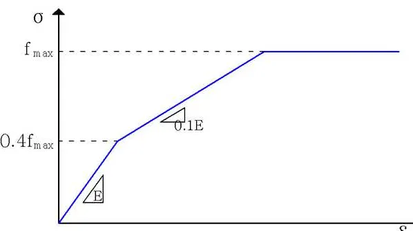
The mechanical characteristics in the direction of wood fibres are generally different when the load is tensile or compressive, due to the buckling and divulsion of wood fibres at microscopic level. In general, wood has greater compressive than tensile strength due to the existing deficiencies and the scale effect. Adequate accuracy can be achieved if wood is approximated as a material with a trilinear constitutive law (σ – ε) under monotonic axial loading, with a horizontal second plastic segment and the same characteristics in tension and compression (Fig. 5). This trilinear behaviour serves in the expansion of the yielding area (isotropic expansion) after introducing plastic deformation (at 40% of the uniaxial ultimate load fmax), up to maximum
strength. A generalisation of von Mises yield criterion, Hill's yield criterion [29] is adopted (equation 1) that accounts for anisotropy in ductile materials.
2 2 2
1 2 3
2
2 2 2
4 5 6
( , )
3 3 3 2
ij yy zz zz xx xx yy
zx yz xy
F a a a
a a a
(1)
where 1 2 2 2
1 1 1
y y y
yy zz xx
a , 2 2 2 2
1 1 1
y y y
zz xx yy
a ,
3 2 2 2
1 1 1
y y y
xx yy zz
a , 4 2 2
3 yzy
a , 5 2
2
3 xzy
a , 6 2 2
3 xyy a
In equations (1) is the relative yield stress which defines the size of the yield surface and σijy are the uniaxial/pure-shear yield stresses in the ij direction.
6 7 8 9 10 11 12 13 14 15 16 17 18 19 20 21 22 23 24 25 26 27 28 29 30 31 32 33 34 35 36 37 38 39 40 41 42 43 44 45 46 47 48 49 50 51 52 53 54 55 56 57
differentiates between tension and compression, but trial analyses have showed
negligible difference in the results. Due to the adopted trilinear model for uniaxial tension (Fig. 5) isotropic work-hardening takes place after the initial yield.
In existing structures, extensive research for the determination of the mechanical characteristics of wood is necessary. The values of the mechanical characteristics generally needed are the ultimate strength in tension and compression parallel and normal to the fibres of wood (fxx, fyy), the modulus of elasticity parallel and normal to the fibres (Exx, Eyy), the ultimate shear strength (fxy), and the shear modulus (Gxy). Normally, it is not feasible to perform all necessary tests to measure the aforementioned mechanical properties. Moreover, destructive testing methods for the assessment of material properties are generally not permitted in historical structures; moreover, there is often a wide scatter in the values of the aforementioned parameters due to the different deterioration in various parts of the building. Therefore, the relationships adopted by the standard EN338 [15] are used here to correlate the flexural capacity of pine wood with the other properties. As mentioned previously, wood is considered as an orthotropic material, the x-direction is parallel to the fibres and the y-x-direction perpendicular to them. The moduli of elasticity, the shear modulus and the strengths should satisfy the following equation (see also [28])
3 3
1, 0.25, 0.2
y y y y
y y
yy y xy xy
xx zz
y y
x xx
f f
f f (2)
6 7 8 9 10 11 12 13 14 15 16 17 18 19 20 21 22 23 24 25 26 27 28 29 30 31 32 33 34 35 36 37 38 39 40 41 42 43 44 45 46 47 48 49 50 51 52 53 54 55 56 57 58 2 2
2 2 2 2
2 2 2
2 2 2
1 1 1 1 1 1
2 2
1 1 1 1
1 2
y x
y y y y
yy xx xx yy
x y xy
y y y
xx yy xy
(3)
This 2D model can be expressed more concisely in the form
2 2 2
2 2 2 2 2
1 1 1 1 1
1
x y xy z
a b a b c (4)
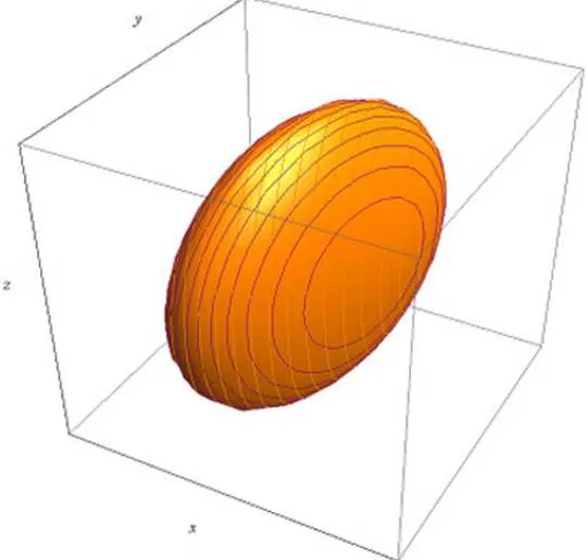
wherein a stands for the yield stress along the x axis, b stands for the yield stress along the y axis, and c for the shear yield stress; equation (4), for a>b represents an ellipsoid (Fig. 6).
The weight of the masonry infills is taken into account indirectly. The specific weight
γ' for the equivalent diagonals of the model is derived as a combination of the original specific weight of the timber diagonals γdiag and the masonry infills γinf according to the following equation
'
inf inf diag diag diag
A A A (5)
where A is the area and γ the specific weight of the item under consideration.
4.2 Modelling of contact between timber elements
6 7 8 9 10 11 12 13 14 15 16 17 18 19 20 21 22 23 24 25 26 27 28 29 30 31 32 33 34 35 36 37 38 39 40 41 42 43 44 45 46 47 48 49 50 51 52 53 54 55 56 57
corrosion and they cannot adequately join the connected members. This connection is considered in the numerical model as a simple contact between the timber members, capable of transferring only compressive loads and, to some extent, shear stress; this type of connection is incapable of carrying tensile stress. Modelling of this type of connection is performed with contact elements. Contact problems are highly non-linear and the estimation of the areas in contact depends on the external loading and the boundary conditions of the problem at each step. Contact elements permit the areas between timber elements to be open or closed, or to slip due to shear, thus being able to describe in an effective way the actual situation. Asymmetric contact elements which allow sliding when maximum shear stress is reached are placed between areas that are initially in contact or can come into contact during the application of loading. The one area is considered as 'target' area and the other as contact area. The constitutive law adopted for contact is the familiar Mohr-Coulomb friction law having the form
max
,
c (6)
where τmaxis the maximum shear stress that can develop at the contact areas, c is the cohesion, μ is the friction coefficient for isotropic friction, and σ is the normal stress at the friction area. When the shear stress τ reaches the value τmax the two contact surfaces start to slip relative to each other. For contact between the surrounding timber frame and the internal diagonals of a conventional panel of a timber-framed building, the friction coefficient μ is considered to be equal to 0.50 [30], while no cohesion is assumed (c=0).
4.3 Validation of the proposed model
6 7 8 9 10 11 12 13 14 15 16 17 18 19 20 21 22 23 24 25 26 27 28 29 30 31 32 33 34 35 36 37 38 39 40 41 42 43 44 45 46 47 48 49 50 51 52 53 54 55 56 57 58
existing 'Pombalino' building of Lisbon (based on the concept described in section 2). These specimens had large dimensions, with about 3.5m height (storey height), about 2.5m width and about 0.15m thickness, excluding the mortar of 25mm on both sides. The experimental setup used in these tests is shown in Fig. 7. Basic geometric data for the specimens and experimental results are presented in Table 1.
The experimental testing involved application of reversed cycles of horizontal loading (Fig. 7) until failure of the specimens was reached. The behaviour of the three specimens was similar; at the final stage of failure they showed disconnection of the wood braces with a consequent sliding and out-of-plane fall of masonry infills.
The above specimens were modelled in ANSYS (Fig. 8) according to the method described in sections 4.1 and 4.2, and were subjected to monotonically increasing horizontal loading (with displacement control). The pine wood of the walls is classified to the C24 (24MPa) category of the EN338. The flexural capacity of the pine wood should be reduced to 18.9MPa taking into account the effect on the strength parameters of the duration of the load and the moisture content in the structure ('Service class II' according to Eurocode-5, which means that the moisture content in timber elements corresponds to temperature 20±2 oC and the relative humidity of the surrounding air exceeds 85% only for a few weeks during the year). Basic data for wood material are then as follows
0
18.9 , 4.77 , 2.25
1
30 11 , 0.36
2 16
y y y
xx yy xy
xx yy
xx yy xy
f MPa f MPa f MPa
E E
E E E GPa G GPa
(7)
6 7 8 9 10 11 12 13 14 15 16 17 18 19 20 21 22 23 24 25 26 27 28 29 30 31 32 33 34 35 36 37 38 39 40 41 42 43 44 45 46 47 48 49 50 51 52 53 54 55 56 57
9 that the contribution of the masonry infills at the post-elastic stage is negligible as they have disengaged from the surrounding timber members and finally most of them have fallen out of the frame, partially or totally. Analytically derived pushover curves are compared in Fig. 10 with the envelope of the hysteresis loops from the tests, while the main results are summarised in Table 2. Good agreement is noted with regard to the ultimate load capacity and the ultimate deformation of the panel, while the elastic stiffness of the analytical model is slightly smaller (about 5%) than that in the test, apparently due to disregarding the masonry infills. However, the pre-peak range of the response is not captured properly during all stages. In particular, the envelope curves of the hysteresis loops for specimens G1 and G2, subsequent to the initial stage, are smoother (lower slope) than the pushover curves of the numerical models; this could be attributed to several factors, such as existing local imperfections and wear of the timber members, which result in an initial slip prior to the activation of the brace, and, of course, the effect of cyclic degradation that, by definition, cannot be captured by pushover analysis. On the contrary, this behaviour was not observed in specimen G3 wherein the analytical pushover curve reasonably matched the experimental envelope curve almost throughout the response. Maximum strengths and maximum displacements of the analytical model and the experimental results are very close to each other (Table 2). The key conclusion from the comparison of the analytical and the experimental results is the ability of the model to capture the salient features of the behaviour of the wall under horizontal loading.
5. Simplified non-linear beam model
6 7 8 9 10 11 12 13 14 15 16 17 18 19 20 21 22 23 24 25 26 27 28 29 30 31 32 33 34 35 36 37 38 39 40 41 42 43 44 45 46 47 48 49 50 51 52 53 54 55 56 57 58
set-up and verification). To overcome this difficulty, a simplified model is proposed in the following, intended for the inelastic analysis of full-scale T-F masonry buildings. The essential difference between the two models lies in the fact that in the simplified model inelasticity is confined to point hinges (lumped plasticity approach).
The following key assumptions are made: First, every timber post and lintel is modelled through a linear-elastic beam element. Then, the diagonals are modelled with a link (bar) element pinned at its ends, hence carrying only axial compressive forces (Fig. 11). These link elements incorporate a plastic axial spring. For the determination of the inelastic constitutive law of this point plastic spring an elastic preliminary analysis is needed to estimate the axial forces in the timber posts. The detailed model is then used to derive the pushover curve (ux=displacement vs.
V=shear force) for each T-F panel of the building, with vertical loads derived from the elastic analysis.
The aforementioned pushover curve is subsequently reduced to a bilinear curve using the familiar assumption of equal areas left by the bilinear pushover curve above and below the original pushover curve (Fig. 12). This bilinear curve is embodied in the diagonals' axial plastic hinges (udiag=deformation, Ndiag=axial load) according to the equations
2 2 2 2
,
diag x diag
H L H L
u u N V
L L (8)
where H and L are the height and the length of the panel. The above equation (8) is valid only for a panel consisting of two X-type diagonals.
6 7 8 9 10 11 12 13 14 15 16 17 18 19 20 21 22 23 24 25 26 27 28 29 30 31 32 33 34 35 36 37 38 39 40 41 42 43 44 45 46 47 48 49 50 51 52 53 54 55 56 57
determined from the maximum capacity and the corresponding strain assuming reasonable ratios between them, a common practice in codes and guidelines. The residual strength ratio is taken equal to 0.20, and the maximum strain to 1.2 times the strain at maximum capacity [31].
To complete the beam element model , consideration of the sliding of the diagonals in the elastic range is required, as it affects the initial stiffness of the panel (the post-elastic effect of sliding is already taken into accounted in the constitutive law of the plastic axial spring). The correction factor ksto be applied to the stiffnesses of the members of the beam model is derived from the ratio of the ‘elastic’ stiffness of the detailed sliding model (yield force Vy divided by yield displacement uy) to the elastic
horizontal stiffness of the braced frame of the simplified model (expressed in terms of its geometry and the axial stiffness of the members)
3 2 2 2 3
2
1 y s
y
H L H V
k
EA L u (9)
where E is the Young's modulus of timber, A is the area of the section. It is noted that the weight of the masonry infills is considered through equation (5).
6 7 8 9 10 11 12 13 14 15 16 17 18 19 20 21 22 23 24 25 26 27 28 29 30 31 32 33 34 35 36 37 38 39 40 41 42 43 44 45 46 47 48 49 50 51 52 53 54 55 56 57 58
adjust the elastic stiffness of the diagonals. For specimen G2 the main results are summarised in Table 3.
Good match was found (Fig. 13) between the experimental values and those derived from the analysis for key response quantities such as maximum shear force (4% lower than in the test), and ultimate displacement (8% lower than in the test). The pushover curve from the analysis has a bilinear shape (Fig. 13) compared to the gradually decreasing slope of the experimental curve; this is a consequence of the constitutive law adopted in the model.
6. Application to an existing building
The simplified model is used for the analysis of the façade of an actual building situated in the Ionian island of Lefkas, Greece (Fig. 14). The analysis is carried out for the first stage of the response where masonry carries the seismic shear at the ground storey, while the secondary system (wooden frame of the ground storey) described in section 2 is not activated yet. This building, known as 'Berykiou', has a basement built in stone masonry of thickness 0.8m and two storeys built in timber-framed masonry. The timber structure of the upper storeys is connected to the ground stone masonry through iron joints. The façades of the building are covered with a thin metal sheet, hence the actual configuration of the diagonal timber members is not exactly known. For this application every T-F frame is considered to consist of two diagonal members (Fig. 15a). The section of timber elements is 100mm square, and the thickness of masonry infills is also 100mm.
6 7 8 9 10 11 12 13 14 15 16 17 18 19 20 21 22 23 24 25 26 27 28 29 30 31 32 33 34 35 36 37 38 39 40 41 42 43 44 45 46 47 48 49 50 51 52 53 54 55 56 57
The pushover curve derived from this analysis is idealised as a bilinear curve. This curve serves as the nonlinear law of the axial hinges of the diagonal links (through equation (8)) and factor ksis calculated. The simulation of the stone masonry of the ground storey is implemented through the equivalent frame model for unreinforced masonry reported in [32]. Values of the Young's modulus in the x direction (Exx) and y direction (Eyy), shear modulus (Gxy), compression strength in the x direction (fc,xx) and y direction (fc,yy), and tension strength in the x direction (ft,xx) and y direction (ft,yy) for the materials used in the analysis are given in Table 4.
The failure mechanism derived from the nonlinear static analysis of the façade (Fig. 15a) is shown in Fig. 15b; the corresponding pushover curve is shown in Fig. 16. It is noted that the diagonal braces of the first floor yield first. Plastic hinges also form in the unreinforced masonry of the ground storey, and at one T-F frame of the second storey. The pushover curve of the building has an almost bilinear form due to the symmetry of the structure that makes hinges (for which a bilinear law is adopted) form almost simultaneously.
7. Conclusions
Two models, a detailed and a simplified one, were proposed for the non-linear static analysis of T-F masonry buildings. The former is intended for the analysis of small subassemblages like individual panels of a T-F building, and the force-displacement curve derived from this model can then provide the constitutive law of the simplified model, which is intended for the analysis of entire buildings.
6 7 8 9 10 11 12 13 14 15 16 17 18 19 20 21 22 23 24 25 26 27 28 29 30 31 32 33 34 35 36 37 38 39 40 41 42 43 44 45 46 47 48 49 50 51 52 53 54 55 56 57 58
found to be appropriate for modelling the behaviour of timber elements. The masonry infill is not considered in the model because of its insignificant contribution to the ultimate resistance to seismic loading. The proposed model can be used in a detailed, displacement-focused, analytical assessment, but is not intended for the analysis of full-scale buildings.
A simplified model was then developed for the non-linear analysis of entire buildings. It involves beam elements for timber posts and lintels, and link elements with nonlinear axial hinges for the diagonals.
Both models were validated using cyclic loading tests on timber-framed masonry-infilled panels. Good match was found between the results of the numerical analyses and those of the tests for most stages of the response. The detailed model can capture the gradual softening in the response of the walls, whereas the pushover curve resulting from the simplified model has an essentially bilinear form. The simplified model is deemed appropriate for seismic fragility assessment of this interesting type of building. This model was used here for the analysis of the façade of an existing T-F building situated in the island of Lefkas, Greece.
Acknowledgements
The first author gratefully acknowledges the financial support provided by the 'Bodossaki Foundation' for carrying out this work.
References
6 7 8 9 10 11 12 13 14 15 16 17 18 19 20 21 22 23 24 25 26 27 28 29 30 31 32 33 34 35 36 37 38 39 40 41 42 43 44 45 46 47 48 49 50 51 52 53 54 55 56 57
[2] T. Makarios, M. Demosthenous, Seismic response of traditional buildings of Lefkas Island, Greece, Eng. Struct. 28 (2006) 264-278.
[3] R. Cardoso, M. Lopes, R. Bento, Seismic evaluation of old masonry buildings. Part I: Method description and application to a case-study, Engineering Structures,. 27 (2005) 2024-2035.
[4] I.N. Doudoumis, J. Deligiannidou, A. Kelesi. Analytical modeling of masonry-infilled timber truss-works, Proceedings of 5th GRACM International Congress on Computational Mechanics, Limassol, June 29 –July 1, 2005.
[5] E. Vintzileou, A. Zagkotsis, C. Repapis, C. Zeris, Seismic behaviour of the historical structural system of the island of Lefkada, Greece, Constr Build Mater. 21 (2007) 225-236.
[6] J.M. Driessen, Earthquake-Resistant Construction and the Wrath of the "Earth-Shaker", The Journal of the Society of Architectural Historians. 46 (1987) 171-178. [7] C. Palyvou, Akrotiri Thiras: I Oikodomiki Techni, Athens, 1999 [in Greek].
[8] K.W. Schaar, Traditional Earthquake-Resistant Construction: The Mycenaean Aspect, The Journal of the Society of Architectural Historians. 33 (1974) 80-81. [9] D. Liberatore, G. Spera, A. Claps, A. Larotonda, The italian archaeological
heritage: a cIassification of types from the point of view of protection against earthquakes, Proceedings of the First International Congress on Construction History, Madrid, 20th-24th January, ed. S. Huerta, 2003, pp.1295-1305.
[10] L.D. Decanini, A. De Sortis, A. Goretti, L. Liberatore, F. Mollaioli, P. Bazzurro, Performance of Masonry Buildings During the 2002 Molise, Italy, Earthquake, Earthquake Spectra. 20 (2004) S221.
6 7 8 9 10 11 12 13 14 15 16 17 18 19 20 21 22 23 24 25 26 27 28 29 30 31 32 33 34 35 36 37 38 39 40 41 42 43 44 45 46 47 48 49 50 51 52 53 54 55 56 57 58
[12] P. Gülkan and R. Langenbach. The earthquake resistance of traditional timber and masonry dwellings in Turkey, Proceedings of the 13th World Conference on Earthquake Engineering, Vancouver, Canada, August 1-6, 2004, Paper No. 2297. [13] J. Homan, W.J. Eastwood, The 17 August 1999 kocaeli (Izmit) earthquake:
Historical records and seismic culture, Earthquake Spectra. 17 (2001) 617-634. [14] R. Langenbach, Survivors among the Ruins: Traditional Houses in Earthquakes in
Turkey and India, APT Bulletin. 33 (2002) 47-56.
[15] EN338, CEN, Structural timber ― Strength classes, Brussels, 2008.
[16] P.S. Santos, Laboratory tests on masonry walls taken from an ancient building in Lisbon, 17/97 (1997).
[17] ANSYS User's Manual, Revision 12.0, Swanson Analysis Systems, Inc., Houston, PA, 2009.
[18] P. Gavrilovič, S.J. Kelley, V. Šendova, A Study of Seismic Protection Techniques for the Byzantine Churches in Macedonia, APT Bulletin. 34 (2003) pp. 63-69. [19] E. Tsakanika, Byzantine and Post – Byzantine Historical Timber Roofs in Greece,
Typical Failures, Misunderstanding of their Structural Behaviour, Restoration Proposals, Proceedings of ICOMOS (Wood committee), 16th International Conference and Symposium, From Material to Structure - Mechanical Behaviour and Failures of the Timber Structures, Florence, Venice and Vicenza, November 11 -16, 2007 (available at http://www.icomos.org/iiwc/2007.htm).
[20] P. Touliatos, The box framed entity and function of the structures: the importance of wood's role, in: G. Tampone (Ed.), Proceedings of Conservation of Historic Wooden Structures, Collegio Ingegneri della Toscana, Florence, February 22-27, 2005, pp. 52-64.
6 7 8 9 10 11 12 13 14 15 16 17 18 19 20 21 22 23 24 25 26 27 28 29 30 31 32 33 34 35 36 37 38 39 40 41 42 43 44 45 46 47 48 49 50 51 52 53 54 55 56 57
[22] D.T.G. Porphyrios, Traditional Earthquake-Resistant Construction on a Greek Island, The Journal of the Society of Architectural Historians. 30 (1971) 31-39. [23] N.D. Karydis, Eressos, Papasotiriou, Athens, 2003 [in Greek].
[24] B. İpekoğlu, An architectural evaluation method for conservation of traditional dwellings, Build.Environ. 41 (2006) 386-394.
[25] Kandilli Earthquake Research Institute. (2010). Boğaziçi Üniversitesi, Istanbul, Turkey. Available at http://www.koeri.boun.edu.tr.
[26] N. Şahin Güçhan, Observations on earthquake resistance of traditional timber-framed houses in Turkey, Build.&Environ. 42 (2007) 840-851.
[27] R. Langenbach, Learning from the past to protect the future: Armature Crosswalls, Eng. Struct. 30 (2008) 2096-2100.
[28] A.M.P.G. Dias, S.M.R. Lopes, J.W.G. Van De Kuilen, H.M.P. Cruz, Load-carrying capacity of timber-concrete joints with dowel-type fasteners, J.Struct.Eng. ASCE 133 (2007) 720-727.
[29] R. Hill, A Theory of the Yielding and Plastic Flow of Anisotropic Metals, Proceedings of the Royal Society of London. Series A, Mathematical and Physical Sciences (1934-1990). 193 (1948) 281-297.
[30] M.A. Parisi and M. Piazza. Mechanics of plain and retrofitted traditional timber connections, J Struct Engng Am Soc Civ Engrs. 126(12) (2000) 1395–1403.
[31] FEMA, Prestandard and Commentary for the Seismic Rehabilitation of Buildings, FEMA 356, Federal Emergency Management Agency, Washington, D.C., November, ch. 8, pp.8.14-8.35, 2000.
6 7 8 9 10 11 12 13 14 15 16 17 18 19 20 21 22 23 24 25 26 27 28 29 30 31 32 33 34 35 36 37 38 39 40 41 42 43 44 45 46 47 48 49 50 51 52 53 54 55 56 57 58
Tables
6 7 8 9 10 11 12 13 14 15 16 17 18 19 20 21 22 23 24 25 26 27 28 29 30 31 32 33 34 35 36 37 38 39 40 41 42 43 44 45 46 47 48 49 50 51 52 53 54 55 56 57 Figure captions
Fig. 1. Examples of T-F structures: (a) building situated in Macedonia, Greece; (b) a regular plane frame of T-F masonry including diagonal bracing.
Fig. 2. Section of T-F masonry of buildings in the Bronze Age Greece: one timber framework on each face of the thick masonry wall.
Fig. 3 Roman T-F construction: (a) The Hall of Augustals: a splendid building of Herculaneum with T-F masonry walls; (b) The Trellis House: a building constructed almost entirely in T-F masonry.
Fig. 4. The courses of red bricks of the Theodosian Walls in Constantinople (408-413 AD) serve as coverage of longitudinal wooden beams.
Fig. 5: Trilinear diagram for timber under monotonic tensile loading.
Fig. 6: The ellipsoid of Hill's criterion (corresponding to σxxy = 18.9MPa, σyyy =
4.77MPa, σxyy = 2.25MPa) in stress space σxx, σyy, τxy. Fig. 7. Setup used at the LNEC tests [16].
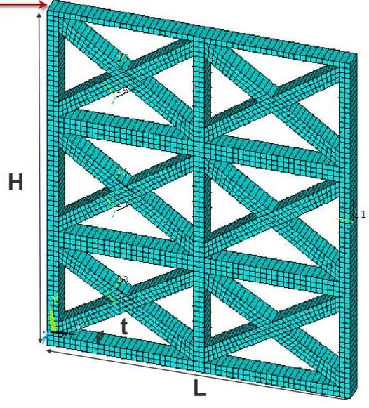
Fig. 8. Modelling of the specimens in ANSYS.
Fig. 9. The ultimate deformed shape of a central node of the wall from the analysis and the test.
Fig. 10. Monotonic loading curves from the analytical model (model) and hysteresis loops from the tests (LNEC) for specimens G1, G2 and G3.
Fig. 11. Modelling of the specimen G2 with the detailed and the simplified beam elements (the bullets represent the plastic spring).
Fig. 12 Derived pushover curve for a plane frame: original curve from the analysis (ANSYS) and idealised curve (BILINEAR).
Fig. 13. Pushover curve of the wall from the analysis (SAP2000) and experimental results (LNEC).
6 7 8 9 10 11 12 13 14 15 16 17 18 19 20 21 22 23 24 25 26 27 28 29 30 31 32 33 34 35 36 37 38 39 40 41 42 43 44 45 46 47 48 49 50 51 52 53 54 55 56 57 58
Fig. 15. The façade of the studied building in Lefkas, Greece: (a) structural system and (b) failure mechanism.
Table 1. Dimensions of the three specimens [length (L), height (H), thickness (t) see Fig. 8] in m and maximum horizontal load (V) in kN.
L H t V
G1 2.53 3.59 0.15 71
G2 2.55 3.42 0.16 71
Table 2. Elastic stiffness (kN/m), maximum strength (kN) and maximum displacement (cm) of the specimens.
elastic
stiffness
max strength (%) max
displacement G1 LNEC test 6733.36 71.61 -60.61 8% 12.50 -10.28
Proposed model 6564.29 65.77 10.00
G2 LNEC test 7711.08 70.98 -63.42 1% 12.28 -9.93
Proposed model 7120.08 70.08 11.50
G3 LNEC test 4361.08 46.77 -59.23 -4% 11.76 -11.42
Table 3. Dimensions of plane frame G2 (m), sliding factor, shear yielding (kN), yield and ultimate displacements (cm), ductility and hardening.
plane frame 1 2 3 4 5 6
L 1.25 1.25 1.25 1.25 1.25 1.25
H 1.15 1.15 1.15 1.15 1.1 1.1
kser 0.21 0.19 0.14 0.10 0.10 0.08
Vy 42.00 41.71 42.29 42.73 42.03 37.08
dy 0.39 0.43 0.58 0.84 0.79 0.84
du 3.36 3.59 3.99 5.14 3.85 6.53
ductility 8.71 8.33 6.86 6.13 4.87 7.75
Table 4. Mechanical characteristics of the materials (MPa) Structural
member Exx Eyy Gxy fc,xx fc,yy ft,xx ft,yy
Masonry 11.0×10³ 4.58×10³ 11.0 1.1
Response to reviewers