City, University of London Institutional Repository
Citation
:
Soomro, A., Amiryar, M. E., Nankoo, D. and Pullen, K. R. ORCID:
0000-0001-8501-9226 (2019). Performance and Loss Analysis of Squirrel Cage Induction Machine
Based Flywheel Energy Storage System. Applied Sciences, 9(21), 4537.. doi:
10.3390/app9214537
This is the published version of the paper.
This version of the publication may differ from the final published
version.
Permanent repository link:
http://openaccess.city.ac.uk/id/eprint/23097/
Link to published version
:
http://dx.doi.org/10.3390/app9214537
Copyright and reuse:
City Research Online aims to make research
outputs of City, University of London available to a wider audience.
Copyright and Moral Rights remain with the author(s) and/or copyright
holders. URLs from City Research Online may be freely distributed and
linked to.
sciences
Article
Performance and Loss Analysis of Squirrel Cage
Induction Machine Based Flywheel Energy
Storage System
Abid Soomro *, Mustafa E. Amiryar , Daniel Nankoo and Keith R. Pullen
School of Mathematics, Computer Science and Engineering, University of London, London EC1V 0HB, UK; [email protected] (M.E.A.); [email protected] (D.N.); [email protected] (K.R.P.)
* Correspondence: [email protected]; Tel.:+44-(0)20-7040-3475
Received: 6 August 2019; Accepted: 18 October 2019; Published: 25 October 2019
Abstract: Flywheel energy storage systems (FESS) are one of the earliest forms of energy storage technologies with several benefits of long service time, high power density, low maintenance, and insensitivity to environmental conditions being important areas of research in recent years. This paper focusses on the electrical machine and power electronics, an important part of a flywheel system, the electrical machine rotating with the flywheel inertia in order to perform charge-discharge cycles. The type of machine used in the electrical drive plays an important role in the characteristics governing electrical losses as well as standby losses. Permanent magnet synchronous machine (PMSM) and induction machines (IM) are the two most common types of electric machines used in FESS applications where the latter has negligible standby losses due to its lower rotor magnetic field until energised by the stator. This paper describes research in which the operational and standby losses of a squirrel-cage induction machine-based flywheel storage system (SCIM-FESS) are modelled as a system developed in MATLAB/Simulink environment inclusive of the control system for the power electronics converters. Using the proposed control algorithm and in-depth analysis of the system losses, a detailed assessment of the dynamic performance of the SCIM-FESS is performed for different states of charging, discharging, and standby modes. The results of the analysis show that, in presence of system losses including aerodynamic and bearing friction losses, the SCIM-FESS has satisfactory characteristics in energy regulation and dynamic response during load torque variations. The compliance of FESS and its conversion between the generating and motoring mode within milliseconds show the responsiveness of the proposed control system.
Keywords: flywheel energy storage; squirrel cage induction machine; loss analysis; field-oriented control
1. Introduction
Cleaner production of energy is urgently needed in today’s world due to the concerns about global warming and growing population. This need has allowed widespread use of distributed generation (DG) and renewable energy sources (RES) integrated to electricity networks [1]. However, due to their dependency on seasonal variations, RES are not completely reliable and stable and cannot be used as the only primary source of energy. Additionally, if renewable sources of energy are added into microgrids powered previously only by fossil fired engines, this intermittency combined with fluctuation in demand leads to further stability challenges. Energy storage systems (ESS) offer a solution, which can mitigate the effects of RES intermittency by providing a balance between electrical supply and demand [2,3]. ESS can also reduce the power rating of the generating engine to meet peak demand and enables power production to meet average demand and reducing generation cost [4]. Also,
Appl. Sci.2019,9, 4537 2 of 26
there are various solutions proposed to ensure network stability and reliability with RES including demand management, interconnection with external grids, and ESS [5].
There are ranges of systems involved in energy storage process, which can convert, store and deliver energy on demand. Performance of these systems depends on the amount of energy they can store, the storage time and delivery of energy with minimum losses [6]. Therefore, high power capability, high efficiency, low capital cost and environmentally friendly attributes improve the value of ESS [7].
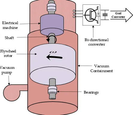
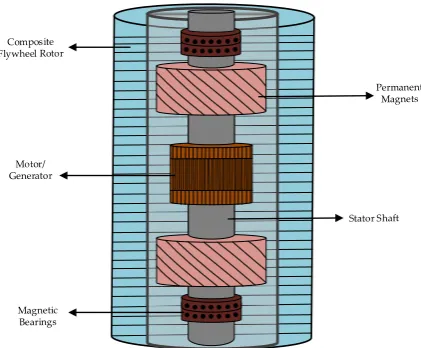
A FESS is an assembly of a rotating mass, electrical machine, power electronics converter, bearing system and containment. The design of the rotor used in FESS depends on the materials from which they are made. Solid disk or solid cylinder are made from isotropic materials like steel. Rim type or hollow cylinder flywheel rotors are constructed from non-isotropic material like composite carbon fiber. Solid disk or solid cylinder flywheel rotors have simple construction and are commonly used [8]. Solid rotor flywheels exhibit less displacement from axes due to centrifugal forces hence simplifying flywheel attachment to the shaft and with electrical machine [9]. Schematic diagram of solid rotor FESS is shown in Figure1.
meet peak demand and enables power production to meet average demand and reducing generation cost [4]. Also, there are various solutions proposed to ensure network stability and reliability with RES including demand management, interconnection with external grids, and ESS [5].
There are ranges of systems involved in energy storage process, which can convert, store and deliver energy on demand. Performance of these systems depends on the amount of energy they can store, the storage time and delivery of energy with minimum losses [6]. Therefore, high power capability, high efficiency, low capital cost and environmentally friendly attributes improve the value of ESS [7].
A FESS is an assembly of a rotating mass, electrical machine, power electronics converter, bearing system and containment. The design of the rotor used in FESS depends on the materials from which they are made. Solid disk or solid cylinder are made from isotropic materials like steel. Rim type or hollow cylinder flywheel rotors are constructed from non-isotropic material like composite carbon fiber. Solid disk or solid cylinder flywheel rotors have simple construction and are commonly used [8]. Solid rotor flywheels exhibit less displacement from axes due to centrifugal forces hence simplifying flywheel attachment to the shaft and with electrical machine [9]. Schematic diagram of solid rotor FESS is shown in Figure 1.
Grid Converter
Bearings Vacuum Containment Vacuum
pump Flywheel
rotor Shaft Electrical machine
[image:3.595.186.409.309.502.2]Bi-directional converter
Figure 1. Structure of solid disk FESS.
Carbon fibre-reinforced composite rim type or hollow cylinder flywheel rotor assembly contains the hub and the flywheel rim, which are mounted together on the metallic shaft [10]. Due to mismatching of strains of hub and the flywheel rim material, attachment of the composite flywheel to the shaft is an issue, due to this issue, integrated hollow flywheel design is introduced recently, in which electric machine and bearing system are integrated in the hub of the flywheel [11]. In this design, the rotor of electric machine is outside of the stator which enables very high-speed design [9]. Integrated hollow flywheels attain high speeds, have more specific energy, less cost, occupy less space and contain less windage losses. However, shaftless hollow flywheel design faces challenges such as heating issues, strength of the rotor materials and suspension of the rotor [9,11]. Schematic diagram of integrated hollow flywheel is shown in Figure 2. This configuration holds an axial type PMSM with two PM rotors and a single stator. In addition, there are some other configurations including the type in which the flywheel and the rotor of the electric machine are combined together as addressed in [12]
Figure 1.Structure of solid disk FESS.
Figure 2. Structure of Integrated hollow FESS.
With fast response time, relatively high-energy density and high-power capability, flywheel energy storage systems (FESS) offer an attractive energy storage solution [13]. FESS is highly suitable for applications where a large number of daily charge-discharge cycles as required for power smoothing, renewable energy integration, stability and power quality improvement [14]. FESS and battery energy storage systems (BESS) can be strong competitors against each other for a number of applications [15], with FESS being best suited and leading the competition for short term and high-power applications. Unlike FESS, performance of BESS is affected by many factors and importantly the temperature dependency [15]. Hence, the BESS is less favorable in countries where temperatures are high throughout the year. BESS cannot withstand high charge-discharge rates and requires quite a large volume to store a larger amount of energy [16]. Moreover, the research findings in [17] show that the probability of a battery storage failure is seven times more likely than that of a flywheel storage which makes BESS less reliable than FESS. However, costs of BESS have reduced significantly in recent years and have the added advantage of durations of around one to two hours so may provide power for longer periods. On the other hand, the cost of flywheels needs to reduce significantly and this is possible with lower cost design and volume manufacture [18].
Recently, FESS technology has been implemented in many applications such as UPS, aerospace, transport, power levelling, wind power and frequency regulations. FESS has been successfully used to secure critical loads during power outages in the microgrid environment [17]. In [19], a low speed FESS has been used as a hybrid UPS composed of an engine generator and a flywheel to improve voltage fluctuations of less than 2%. To support emergency loads when main grid supply is disconnected, a successful utilisation of a FESS used as a UPS instead of BESS is reported in [20]. As an alternative to batteries, the flywheel technology has been used for removing DC voltage ripples [21], short-term ride through [22], fast balancing of power in microgrids [23], and islanded solar PV systems [24].
[image:4.595.192.403.89.263.2]The electrical machine is a key part of a FESS which performs the charge-discharge cycles and can be responsible for major losses in the process. The choice of electrical machine must be carefully made according to the application requirements. Machines commonly used in FESS are induction machines (IM), permanent magnet synchronous machines (PMSM), switched reluctance machines (SRM) and homopolar synchronous machines (HSM). SRM have robust design, fault tolerant capability and ability to operate in high temperature environments; however, it is less commonly used because of its complex torque current and high current ripples [25]. Due to the use of electromagnets, SRM can be completely demagnetised [6] that would lead to no idling losses at zero torque (no load) [26]. Highly nonlinear behavior of SRM makes selection of suitable control gains difficult and this makes design of control system challenging and problematic [27]. In the generator mode, SRM require excitation to produce power [25] produced by means of electronic converter [28], but it will result in extra losses. PMSM is used in high-speed applications due to its very high
Figure 2.Structure of Integrated hollow FESS.
With fast response time, relatively high-energy density and high-power capability, flywheel energy storage systems (FESS) offer an attractive energy storage solution [13]. FESS is highly suitable for applications where a large number of daily charge-discharge cycles as required for power smoothing, renewable energy integration, stability and power quality improvement [14]. FESS and battery energy storage systems (BESS) can be strong competitors against each other for a number of applications [15], with FESS being best suited and leading the competition for short term and high-power applications. Unlike FESS, performance of BESS is affected by many factors and importantly the temperature dependency [15]. Hence, the BESS is less favorable in countries where temperatures are high throughout the year. BESS cannot withstand high charge-discharge rates and requires quite a large volume to store a larger amount of energy [16]. Moreover, the research findings in [17] show that the probability of a battery storage failure is seven times more likely than that of a flywheel storage which makes BESS less reliable than FESS. However, costs of BESS have reduced significantly in recent years and have the added advantage of durations of around one to two hours so may provide power for longer periods. On the other hand, the cost of flywheels needs to reduce significantly and this is possible with lower cost design and volume manufacture [18].
Recently, FESS technology has been implemented in many applications such as UPS, aerospace, transport, power levelling, wind power and frequency regulations. FESS has been successfully used to secure critical loads during power outages in the microgrid environment [17]. In [19], a low speed FESS has been used as a hybrid UPS composed of an engine generator and a flywheel to improve voltage fluctuations of less than 2%. To support emergency loads when main grid supply is disconnected, a successful utilisation of a FESS used as a UPS instead of BESS is reported in [20]. As an alternative to batteries, the flywheel technology has been used for removing DC voltage ripples [21], short-term ride through [22], fast balancing of power in microgrids [23], and islanded solar PV systems [24].
due to its rugged construction, is used for high power applications [29]. A challenge for IM is the mechanical design in high-speed application, which can be overcome by using appropriate solid-rotor topologies such as slotted solid rotor, coated solid rotor, caged solid rotor and smooth solid rotor [25]. Homopolar synchronous machines (HSM) are used for long-term energy storage in high speed and high efficiency applications. HSM have robust rotor design and due to their lower standby losses compared to PMSM, they can be used an alternative to PMSM in high-speed applications [25,30]. However, the main disadvantage is the difficult design of HSM due to its complex magnetic flux paths and geometry [31].
Many researchers have studied induction machine-based FESS, but a thorough analysis of the performance of IM in FESS is lacking [32–36]. An IM-based FESS and its associated control strategies for wind energy system applications is presented in [37] and performance analysis of an IM-FESS for use as a UPS for compensation of momentary voltage drops is discussed in [38]. However, analysis of the IM losses as well as the methods for determination of flywheel idling losses is neglected in both papers. Authors in [39] discuss the model and control of an induction machine for flywheel applications focusing on frequency regulation, however, the dynamic performance of the IM and analysis of the control system is lacking. The research in [40] discusses a simple flywheel storage system for DC microgrid proposing an open loop volt/hertz control system governing the energy flow of the FESS. However, the volt/hertz control system is inefficient to achieve high performance [41] since the FESS is a dynamic system and needs efficient control system to achieve dynamic stability and fast flow of the energy.
In this paper, a model for an induction machine driven flywheel storage system has been developed and described with detailed simulation results presented. A detailed loss analysis of the IM has been studied and embedded in the model as developed in MATLAB/Simulink. In addition, the performance of the machine is analysed for motoring and generating modes controlling the charge-discharge cycles of the flywheel storage. Following the introduction, a brief background of the flywheel history along with its theory and structure are described in Section2. The loss analysis of the system as described including standby losses and operational losses are studied in Section3. A detailed analysis of the proposed control strategies and development of the model of IM driven flywheel system is presented in Section4. The analysis of results is presented in Section5. The results are discussed and conclusion is made in Section6.
2. Flywheel Theory and Structure
2.1. Background
reduce peak currents drawn from any other storage system such as BESS that results in improving life of the battery [13]. Flywheel technology can replace battery systems in aerospace applications as it has been found that FESS would be 35% lighter and 55% smaller compared to BESS for EOS-AMI type spacecraft [48]. Flywheels are commonly used for ride through applications mainly to improve power quality. Flywheels have also been used for voltage regulation [34] and spinning reserves for sensitive loads in data centers [17]. They are integrated to solar photovoltaic (PV) system for load levelling [49], harmonic compensation [35], high power UPS system for plasma experiments [50], and in the distribution network to improve power reliability [36].
2.2. Components of FESS
A flywheel storage system works in three modes of acceleration, standby and deceleration. The structure of FESS consists of a bearing system, motor/generator set, flywheel rotor, power electronics and a low-pressure vacuum containment. All these components together determine the overall efficiency of the FESS and are briefly described in this section.
2.2.1. Flywheel Rotor
The rotor of the flywheel is a rotating massm(kg) with inertiaJ(kg·m2) that spins at an angular velocity ofω(rad/s) and stores kinetic energyE(joules) as given by Equation (1).
E= 1
2Jω
2 (1)
The useable stored kinetic energy of a flywheel spinning between a minimum and maximum velocity ofωis given by:
E= 1
2J(ω 2
max−ω2min) (2)
where the moment of inertiaJis a function of flywheel geometry and mass. In case of a disc type flywheel with massm(kg), densityρ(kg/m3) and lengthl(m), the angular velocity can be expressed by Equation (3):
ω= 2
r s
E
ρπl (3)
Therefore, the stored energy is expressed by Equation (4) [51].
E= 1
4mr 2(ω2
max−ω2min) (4)
In the case of a cylindrical type flywheel with an inner radiusr1and outer radiusr2, the stored kinetic energy is given by Equation (5).
E= 1
4m(ω 2
max−ω2min)
r22−r2
1
(5)
2.2.2. Electric Machines
Table 1.Advantages and drawbacks of commonly used electrical machines in FESS [13,25,47,52,53].
SCIM PMSM SRM
Advantages
Rugged construction Simple rotor design Robust simple structure
No risk of demagnetization
High power, high load
and high torque density High power density
Low cost
Easy to install and maintain due to
smaller size
Low cost
High efficiency (93.4%) Very high efficiency
(95.5%) High efficiency (93%)
No idling losses due to its lower rotor magnetic field at zero torque value,
consequently this reduces a total electrical
loss of IM
No field winding losses due to use of permanent magnets
No idling losses
High torque and high power capability
Suitable to operate in low pressure vacuum with
negligible rotor losses
Wide speed range
Drawbacks
Difficult mechanical design for high speed applications
Risk of sudden demagnetization
Significant rotor eddy current losses due to the
time varying magnetic field
Difficult to operate in absolute vacuum due to
complex heat transfer system
Due to use of permanent magnets, PMSM have
low tensile strength
High torque and current ripples
Limited speed and
larger volume High cost
Difficult to regulate speed
Copper losses in electromagnets during
field excitation due to high inrush currents
Idling losses at zero torque due to presence of
magnetic field
High losses due to need of excitation
2.2.3. Bearing Systems
The bearing system supports the rotor and allows the flywheel to spin freely. The selection of bearing system depends on many factors but importantly on its lifetime, weight and level of acceptable losses [54]. There are two types of bearings commonly used in FESS: (1) mechanical bearings and (2) magnetic bearings. Mechanical bearings are simple in structure but have major losses due to friction and deterioration of lubricants and they require maintenance such as lubrication replacement. Magnetic bearing systems work using magnetic levitation and do not have any contact with the mechanical shaft of the flywheel. They are stable but low loss bearing systems due to less friction and are suitable for high-speed applications in FESS [55]. Magnetic bearings that use permanent magnets for levitation are called passive magnetic bearings whereas active bearings are the type that make use of a feedback system with electrical coils [56]. Active magnetic bearings require continuous power for energisation of the magnetic levitation system [13].
rotational losses to less than 2% per day of stored energy. Compared to magnetic and mechanical bearing, HTS bearings incur half of the rotational loss of conventional mechanical bearings [59].
2.2.4. Power Electronics Interface
The electrical machine is connected to a power electronics converter interface in order to make power flow from the electrical grid to the FESS and back to the grid during the acceleration and deceleration of the flywheel. Bi-directional converters help exchange power between the grid and FESS by controlling the operation of the electrical machine. The power electronics converter, which is near to electrical machine, controls rotor magnetic flux and speed of the electrical machine with a suitable modulation technique to produce the gate pulses for the converter. An AC-DC converter (grid side converter) with suitable modulation technique is used to maintain a constant DC-link voltage by following grid side reference currents to control flow of active and reactive power [14]. The design of the converter and its switching technique are responsible for the power quality of the system considering that nearly sinusoidal stator currents, low total harmonic distortion THD (less than 5%) and stable DC-link voltage are the factors affecting the power quality in FESS [60]. The combination of AC-DC-AC power converters is called the back-to-back (BTB) configuration and is the most widely used topology in FESS applications [53]. Oliveira in [61] has discussed implementation and control of AC-DC-AC in FESS. A new DC-DC boost inverter topology used for low speed flywheels is proposed in [62]. Different topologies of power electronics converters used in FESS are discussed in details in [25].
2.2.5. Containment
The flywheel rotor must be enclosed in containment casing for the purpose of safety and reducing aerodynamic losses. The containment could prevent collateral damage which can happen due to the bearing failure releasing the rotor or rotor failure itself or growth of a crack in case of solid steel rotor flywheel. A fatigue crack may grow to cause the rotor to break in large fragments and can cause huge damage to surroundings. In the case of carbon composite flywheel rotors, failure occurs due to circumferential fractures of rotor in layer or propagation of cracks in the rotor. This can cause the rotor to disintegrate into rings or may result into the fragments and powder of carbon fiber that is highly flammable [63]. The rapid disintegration of a composite rotor can also lead to a very high-pressure build up only contained by thick casing or bunkering. In order to increase further safety of solid steel and carbon composite flywheels, they are installed in underground bunkers [46]. This can be eliminated by use of laminated steel designs which greatly limit any rotor failure to small energy release. If the casing is not sufficiently good, horizontal axle FESS has more possibility of mass center displacement than vertical axle FESS that causes instability of the rotor [13]. The aerodynamic losses are reduced by creating a low-pressure environment for the rotor in the containment. Depending on the peripheral speed of the flywheel, containments are made of high strength steel or composite materials [53]. For higher speed flywheels, containment is filled with helium or completely evacuated in order to reduce rotor stress and windage losses, considering that the windage losses are negligible for less than 1 mbar pressure [59].
3. Loss Calculation of IM Driven FESS
There are different losses in a FESS including power converter losses, stator losses and rotor losses all of which fall into the category of electrical losses and contribute to the conversion efficiency. The mechanical losses of the system are mainly due to the bearing losses and aerodynamic or windage losses. The power balance Equation for squirrel cage induction machine FESS (SCIM-FESS) is given by Equation (6).
where:
Pag=Pin−Pscl−Ps f e (7)
Pout=Pin−Pscl−Prcl−Pr f e−Ps f e−Pmech (8)
Pin =Pout+Pscl+Prcl+Pr f e+Ps f e+Pbearing+Pwindage (9)
where Pag is the power transferred from stator to rotor of IM across the air-gap, Pin is the input
power, Pout is total output power, Pscl is stator copper loss of IM, Prcl is rotor copper loss of IM,
Pr f eandPs f eare core losses in the rotor and stator,PbearingandPwindageare bearing and windage losses
of FESS, respectively.
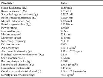
3.1. SCIM-FESS Design and Parameters
[image:9.595.125.471.383.645.2]In this research, the considered flywheel system is a cylindrical rotor type made of steel laminates and operated in very low-pressure vacuum running between a speed range of 10–20 krpm. The type of bearings used are single row radial ball bearings with micro drip type of lubrication. Table2shows the parameters of the electrical machine and other necessary parameters used in SCIM-FESS system design. The detailed calculation and analysis of the switching and conduction losses in power electronics converters are not carried out here but assumed with a fixed value not to exceed more than 2% of the total energy produced in one cycle. This is added to the electrical and mechanical losses when the total system losses are calculated.
Table 2.Values of coefficients and parameters of SCIM-FESS.
Parameter Value
Stator Resistance(Rs) 11.85 mΩ
Rotor Resistance(Rr) 9.29 mΩ
Stator leakage inductance(Lls) 0.2027 mH
Rotor leakage inductance(Llr) 0.2027 mH
Mutual Inductance(Lm) 9.295 mH
Rated magnetic flux(λm) 0.75 Weber
Power rating 100 kW
Nominal torque 90 N·m
Maximum speed 20 krpm
Minimum speed 10 krpm
Switching frequency 20 kHz
DC bus voltage 600 V
Air density (ρ) 0.0011 kg/m3
Air dynamic viscosity(µ) 1.91×10⁻⁵kg/m·s
Flywheel rotor outer diameter(Dr0) 0.4 m
Shaft diameter(Ds) 0.025 m
Bearing design factor(fL) 0.0005
Kinematic oil viscosity(V0) 130×106m2/s
Lamination thickness (t) 0.15 mm
Conductivity of electrical steel (σ) 2.08×10⁶Siemens/m Density of electrical steel (ρ) 7650 kg/m3
3.2. Electrical Losses
The electrical losses in FESS are mainly the due to the stator and rotor losses in the motor/generator set. The stator electrical losses are the combination of copper losses (Pscl) in the stator winding and
core losses (Pcore) in the stator core. The stator copper losses are proportional to the square of the RMS
magnitude of stator currentsIsand is dependent on the value of the stator resistanceRs. Core losses
magnetic flux densityBm. Equation (10) presents the general relation of core losses in the electrical
machine while the total electrical losses in the stator of IM are given by Equation (11).
Pcore=
Khysfe+Kefe2
B2m (10)
Pstator =3I2sRs+
Khysfe+Kefe2
B2m (11)
whereKhysis the Steinmetz co-efficient,Bmis peak magnetic flux density andKeis a constant factor as
given by Equation (12) [64].
Ke= π
2t2σ
6ρ (12)
where t is the thickness of laminations, σ is electrical conductivity and ρ is the density of the electrical steel.
The rotor copper losses (Prcl) are also a combination of copper and rotor iron losses (Pcore) and are
given by Equation (13).
Protor=3Ir2Rr+
Khysfsl+Kefsl2
B2m (13)
where, fsl=s fe,sis the slip,Rris rotor resistance andIris the RMS magnitude of rotor currents in one
phase of the rotor.
For calculation of Steinmetz coefficient(Khys), Equation (10) is divided by the termfeB2mto create
a linear relationship.
Pcore
feB2m
= (x+y fe) (14)
where,x=Khysandy=Kewhich can be simply calculated by substituting the values of parameters
(t,ρandσ) into Equation (12) provided in Table2givingy =3.34×10⁻³Hz. The value ofxcan be calculated by linear fitting of Equation (14) for the best approximation of the data.
The stator and rotor core of the IM are assumed to be made of electric steel M470-50HP. Manufacturer’s core loss data for M470-50HP is shown in Table 3 where the core loss data for specific electrical frequencies of 50 Hz, 100 Hz, 200 Hz and 400 Hz is provided. The electrical frequency of SCIM-FESS presented in this paper at 20 krpm is 333 Hz that lies between 200 Hz and 400 Hz. Therefore, the values ofBmat 333 Hz is approximated between 0.6–0.7 Tesla as calculated based on the
[image:10.595.95.501.554.687.2]methodology discussed in [65].
Table 3.Manufacturer’s loss data for M470-50HP electrical steel. Adapted with permission from [66], Cogent Power Inc., 2019.
Bm(T) W/kg at 50 Hz W/kg at 100 Hz W/kg at 200 Hz W/kg at 400 Hz
0.1 0.03 0.07 0.23 0.58
0.2 0.13 0.29 0.84 2.14
0.3 0.26 0.61 1.71 4.37
0.4 0.43 1.00 2.78 7.17
0.5 0.63 1.46 4.03 10.6
0.6 0.85 1.98 5.48 14.7
0.7 1.09 2.55 7.12 19.6
0.8 1.34 3.19 9.02 25.4
0.9 1.62 3.91 11.2 32.4
1 1.94 4.71 13.7 40.6
Substituting the values ofxandyin Equation (14), the relation ofPcorecan be written as:
Pcore=
0.0487fe+1.4×10⁻³fe
Using Equation (15) and substituting the values of resistances into Equations (11) and (13), the total electrical losses of the stator and rotor are given by:
Pstator=
0.099I2s+0.048fe+1.4×10⁻³fe
(16)
Protor=
0.027I2r
+9.6×10⁻⁴fe+2.8×10⁻⁴fe (17) 3.3. Mechanical Losses
3.3.1. Windage Loss
The windage losses in a FESS are due to the friction between the rotating surfaces and the surrounding medium, which is air in most cases. The windage loss increases with increase of the flywheel speed and is proportional to the cube of the flywheel angular velocity [67]. The windage losses of the FESS housed in a containment for the pressure of>100 Pa is given by Equation (18).
Pw = 1
64Cmω 3ρ
D5r0−D5
r1
(18)
whereCm= 3.87√R
e is the torque coefficient,Re is the Reynolds number and is given byRe =
r ρωD2
r0
4µ , ρis the coolant density andµis the dynamic viscosity of air [3].
For the high-speed rotor flywheels operating in low air pressure environments (0.1 Pa to 10 Pa), windage losses of the FESS is given by Equation (19) [68].
Pw = P
2 r
2π RTω
2a4 (19)
where,Pis the gas pressure,ais radius of the rotor disk andRis the gas constant. By substituting values of parameters (ReandCm) and coefficients from Table2in Equations (18) and (19). The simplified
Equations for windage losses can be written as:
(
Pw=4.5×10⁻⁷ω2.5 P≥100
Pw =6.6×10⁻⁶ω2 P≤10 (20)
3.3.2. Bearing Losses
The bearing losses are usually calculated using the empirical methods as recommended by the bearing manufacturers. However, due to the complexity of the empirical method, in this paper the bearing power losses are calculated using the analytical method. Considering the rotating contacts, the bearing losses in FESS can be defined by Equation (21) [69].
tb=tl+tv+tf (21)
where,tlis the torque due to an applied load and depends on the type of the load and design of bearing,
tf is end flange friction torque which is only applicable in roller type bearings and is negligible in ball
bearings, andtvis the torque due to viscous friction that is dependent on the speed and property of the
lubricant used. The values fortlandtvcan be calculated using Equations (22) and (23), respectively [70].
tl = flFbDp (22)
tv=10−7f0(v0n)
2 3D3
p v0n≥2000
tv=160×10−7f0(v0n)
2 3D3
p v0n<2000
where flis the design dependent factor and is defined by Equation (24).
fl =z
F
s
Cs
y
(24)
whereCsis static load rating defined by the manufacturer’s datasheets andFsthe static equivalent load.
The values of z and y depend on the type and contact angle of the bearing as given in Table4.Fbis
[image:12.595.84.511.231.297.2]load on the bearing,Dpis the pitch circle diameter (m),nis the bearing speed (rpm),v0is kinematic oil viscosity (centistokes) and f0is a lubrication factor which depends on type of bearing and lubrication.
Table 4.Values ofzandy.Adapted with permission from [69], Taylor and Francis Group LLC, 2019.
Bearing Type Nominal Contact Angle (Degrees) z y
Radial deep-groove 0 0.0004–0.0006 0.55
Thrust 90 0.0008 0.33
Double-row self-aligning 10 0.0003 0.4
Angular-contact 30–40 0.001 0.33
The power losses of the ball bearing can be simply defined in terms of the bearing torque and speed as presented in Equation (25) [71].
Pbearing= (tl+tv)ω (25)
Substituting the values of the parameters from Tables2and3, Equation (25) can be simplified as:
Pbearing=0.013ω+2.67×10
−4
ω1.66 (26)
3.3.3. Stray Losses
Stray losses are caused by the magnetic flux leakages of an electrical machine and can be categorised as the stator and rotor stray losses. Due to very little changes in the magnetic flux distribution of the IM stator from no load to full load, stray load losses in the stator of the IM can be neglected. Stray losses in the rotor of IM is a function of the frequency and depends on the rotor slip. In a squirrel cage induction machine (SCIM) with small slip, rotor stray losses are very small and can be neglected [72]. However, during normal operation where the IM operates at full or partial load, these losses cannot be neglected and can be estimated using Equation (27) as recommended by IEEE standards for calculating stray losses in electrical machines [73].
Pstray=0.005
P2g
Pr (27)
wherePgis the generated power or output power of the machine andPris the rated power.
4. Design and Control of SCIM-FESS
The general schematic of the model discussed in this paper is presented in Figure3. The flywheel rotor coupled with the SCIM is modelled as an inertia added to the shaft of the SCIM. The dynamics of SCIM-flywheel can be analysed and represented by Equation (28).
J0dω
dt =Te−Bω (28)
whereTe(N·m) is the electromechanical torque,ω(rad/s) is the angular velocity of the flywheel,J0is the combined inertia (J0= JSCIM+Jf lywheel)of the IM and flywheel rotor (kg·m2) andBis the damping
The dynamic equations of the stator and rotor voltages of the SCIM are presented in Equations (29) and (30), respectively. For the ease of analysis and modelling of the control schemes, time varying sinusoidal quantities are transformed intod-qsynchronous rotating frame by Park’s transformation. A detailed analysis and description of the dynamic model of SCIM is discussed in [74].
(
vds =Rsids−ωeλqs+dtdλds
vqs=Rsiqs+ωeλds+dtdλds
(29)
(
0=Rridr−(ωe−ωr)λqr+dtdλdr
0=Rriqr+ (ωe−ωr)λdr+dtdλqr (30)
where,RrandRsare rotor and stator resistances (ohms),vdqsis the stator voltage ind-qreference frame
(V),λdqrandλdqsare rotor and stator magnetic flux linkages ind-qreference frame (Wb),idqrandidqs
are rotor and stator currents ind-qreference frame (A), andωeis the stator electrical speed (rad/s).
Appl. Sci. 2019, 9, x 12 of 27
where, and are rotor and stator resistances (ohms), is the stator voltage in d-q reference frame (V), and are rotor and stator magnetic flux linkages in d-q reference frame (Wb), and are rotor and stator currents in d-q reference frame (A), and is the stator electrical speed (rad/s).
M
M
Measurement and Control Machine side Converter Control Grid side Converter Control Grid Side Converter Machine Side Converter DC-Link SCIMMG
AC Micro Grid
[image:13.595.97.507.276.474.2]Fly w h ee l iabc ω iabc Gate pulses Gate pulses Vdc
Figure 3. Schematic diagram of FESS.
The three-phase currents and the power flow from the electric grid are controlled by a vector-controlled grid side converter (GSC). The GSC acts as a rectifier or an inverter during acceleration and deceleration modes, respectively. Also, it regulates the DC-link voltage and the reactive currents exchanged with the electric grid. The speed and position of the flywheel are controlled by the machine side converter (MSC) that is connected to the GSC through a DC-link capacitor.
The three-phase currents of the machine and grid, the DC-link voltage and the position and speed of flywheel shaft are measured quantities, which are inputs to the measurement and control block. The control block calculates the position of the shaft and compares the measured quantities with reference values to generate the gates pulses for GSC and MSC. During acceleration mode of the flywheel when power is consumed from the electric grid, the GSC acts as a rectifier and MSC acts as an inverter. When the flywheel reaches its reference speed value, no energy conversion occurs and it switches to standby mode, during which, the flywheel runs at an optimum speed except for the marginal speed decrease due to standby losses. In contrast, when a disturbance occurs in an electric grid, the flywheel starts to decelerate (discharge), the GSC acts as an inverter and MSC operates as a rectifier.
4.1. Control Structure of SCIM-FESS
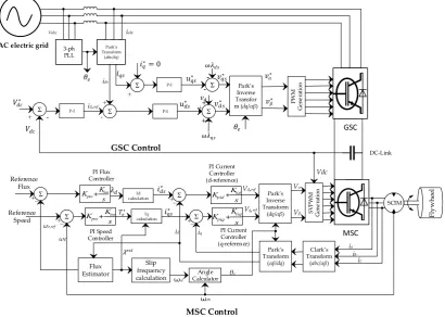
Important quantities to be controlled in a FESS are the DC-link voltage ( ), electromagnetic torque ( ), speed ( ) and position of the rotor magnetic flux vector ( ) during acceleration and deceleration of the flywheel when operating within a specified range of speed. Field oriented control (FOC) and space vector pulse width modulation (SVPWM) have been utilised to control the gate pulses of MSC and GSC. Figure 4 shows a detailed control structure of both converters.
Figure 3.Schematic diagram of FESS.
The three-phase currents and the power flow from the electric grid are controlled by a vector-controlled grid side converter (GSC). The GSC acts as a rectifier or an inverter during acceleration and deceleration modes, respectively. Also, it regulates the DC-link voltage and the reactive currents exchanged with the electric grid. The speed and position of the flywheel are controlled by the machine side converter (MSC) that is connected to the GSC through a DC-link capacitor.
The three-phase currents of the machine and grid, the DC-link voltage and the position and speed of flywheel shaft are measured quantities, which are inputs to the measurement and control block. The control block calculates the position of the shaft and compares the measured quantities with reference values to generate the gates pulses for GSC and MSC. During acceleration mode of the flywheel when power is consumed from the electric grid, the GSC acts as a rectifier and MSC acts as an inverter. When the flywheel reaches its reference speed value, no energy conversion occurs and it switches to standby mode, during which, the flywheel runs at an optimum speed except for the marginal speed decrease due to standby losses. In contrast, when a disturbance occurs in an electric grid, the flywheel starts to decelerate (discharge), the GSC acts as an inverter and MSC operates as a rectifier.
4.1. Control Structure of SCIM-FESS
Important quantities to be controlled in a FESS are the DC-link voltage (Vdc), electromagnetic
torque (Te), speed (ωm) and position of the rotor magnetic flux vector (θe) during acceleration and
(FOC) and space vector pulse width modulation (SVPWM) have been utilised to control the gate pulses of MSC and GSC. Figure4shows a detailed control structure of both converters.
Appl. Sci. 2019, 9, x 13 of 27
Park’s Transform
(abc/dq) 3-ph
PLL
Σ P-I id,ref Σ ids P-I Σ ∗ ∗ Park’s Inverse Transfor
m (dq/αβ)
∗ ∗ PW M Ge n e ra ti o n Σ P-I
∗= 0
∗
M
GSC Control GSC MSC Park’s Inverse Transform(dq/αβ)
Σ Σ +_ +_ ωe,ref ωe s K K i
p
PI Speed Controller PI Current Controller (q-reference) s K K iiq
q pi, , Σ
_+ s
K
K i
p PI Flux Controller Σ +_ PI Current Controller (d-reference) s K
K iid
d pi , , SV P W M Gene ra ti o n Vα Vβ DC-Link Fl y w h eel SCIM Clark’s Transform
(abc/αβ)
Park’s Transform
(αβ/dq)
ia ib ic Angle Calculator id θe iq
Vd,ref
Vq,ref
Id calculation Flux Estimator Slip frequency calculation ꙍm ꙍsl Reference Flux Reference Speed Iq calculation MSC Control iabc
AC electric grid
Vabc Vdc + -+ -++ -+ Σ -+ ∗ ∗ ∗ ∗ ∗
Figure 4. Control structure of machine side converter (MSC) and grid side converter (GSC) in squirrel-cage induction machine-based flywheel storage system (SCIM-FESS).
4.1.1. Machine Side Converter Control
The FOC controls the torque producing current (iq) and magnetic flux producing current (id) separately leading to a simple control structure as of a DC machine with less uncertainty of parameter variations [75]. As shown in Figure 4, the feedback loop is formed by measuring three-phase stator currents, which are then transformed into the synchronous d-q reference frame by Park’s transformation. DC stator currents and are compared with reference currents ∗ and ∗ using PI current controllers which will produce reference voltage signals ∗ and ∗ for generating gate pulses for MSC by SVPWM modulator. Flux estimator calculates the actual magnitude of rotor magnetic flux using Equation (31) which is then compared with the reference flux. Reference d-q axis currents ∗ and ∗ are calculated using Equations (32) and (33) respectively by currents ( ) calculator blocks. Calculated reference values of stator currents in synchronous d-q reference frame are compared with actual stator currents to produce reference voltages ( and
). The rotor flux angle is a crucial parameter in this control technique and it is used to determine the position of rotor flux in IM as calculated using Equations (34) and (35).
=
1 +
(31)∗
=
(32)∗
=
2
3
∙
2
∙
∙
∗ (33)= ( + ) (34)
[image:14.595.94.505.135.427.2]=
∗∗∙
1
(35)Figure 4. Control structure of machine side converter (MSC) and grid side converter (GSC) in squirrel-cage induction machine-based flywheel storage system (SCIM-FESS).
4.1.1. Machine Side Converter Control
The FOC controls the torque producing current (iq) and magnetic flux producing current (id) separately leading to a simple control structure as of a DC machine with less uncertainty of parameter variations [75]. As shown in Figure4, the feedback loop is formed by measuring three-phase stator currents, which are then transformed into the synchronousd-qreference frame by Park’s transformation. DC stator currentsidsandiqsare compared with reference currentsids∗andiqs∗using PI current controllers
which will produce reference voltage signals vds∗ and vqs∗ for generating gate pulses for MSC by
SVPWM modulator. Flux estimator calculates the actual magnitude of rotor magnetic flux using Equation (31) which is then compared with the reference flux. Reference d-q axis currentsi∗dsand i∗qsare calculated using Equations (32) and (33) respectively by currents (idand iq) calculator blocks.
Calculated reference values of stator currents in synchronousd-qreference frame are compared with actual stator currents to produce reference voltages (Vdre f andVqre f). The rotor flux angle is a crucial
parameter in this control technique and it is used to determine the position of rotor flux in IM as calculated using Equations (34) and (35).
λest= Lmid
1+sTr (31)
i∗ds= λd
Lm (32)
i∗qs= 2
3· 2 P· Lr Lm ·T ∗ e
θe =
Z
(ωm+ωsl)dt (34)
ωsl=
i∗qs
i∗
ds
·1
Tr (35)
whereλestis an estimated flux,λdis d-axis rotor magnetic flux linkage,T
∗
eis the reference electromagnetic
torque produced by PI controller,LmandLris mutual inductance and rotor inductance respectively,
ωslis the slip frequency,Tris the rotor time constant,i∗dsandi∗qsare the reference stator currents.
4.1.2. Grid Side Converter Control
A direct vector control scheme is used to controlidandiqin order to regulate the DC-link voltage
during the charge, discharge and standby modes of the flywheel (Figure4). Input variables to the controller are three phase currents (iabc), three-phase voltages (vabc), grid frequency (ω) at the point
of grid connection and DC-link voltage (Vdc). The reference input variables to the controller are
reference DC-link voltage (V∗dc) and d-axis reference current (i∗ds), which is produced by a DC voltage regulator. The compensator term (ωλdqs =ωLgidqs) eliminates coupling between d-q axis components
and also reduces the error in the reference voltage (v∗ds) produced by P-I regulator in order to accurately produce command voltage for modulation and generation of gating signals for switching devices. Using reference voltages, (v∗dsand v∗ds) the controller produces the set point values of voltages in the stationary reference frame (v∗
αβ) at the terminals of the IGBT voltage source converter to produce PWM switching pulses at the desired frequency. For simplification of control system d-axis component of two-phase system is oriented to the direction of grid voltage vector, therefore the grid side voltage (vs) is equal to d-axis voltage (vd) of two phase coordinate frame (vs =vd) and q-axis component is
gained asvq=0 [76]. The angle for transforming three-phase currents (iabc) into d-q reference frame is
provided by phase locked loop (PLL) at grid frequency. The control strategy of the GSC is shown in Figure4and is governed by Equations (36) [77].
Lgdidtds =−Rgids+ωλqs+vs−v∗ds
Lg diqs
dt =−Rdiqs−ωλds−v
∗
qs
(36)
where Lg and Rg are grid side inductance and resistance, vs is grid side voltage. In this control
strategy, a unity power factor is assumed, therefore,iq =0 andid,re f are generated by a PI controller by
comparing the reference and measured dc voltage (Vdc).
5. Results and Analysis
Figure 5. MATLAB/Simulink model of SCIM-FESS.
5.1. Acceleration Mode
The flywheel starts to accelerate when a positive torque of 90 N·m is applied and is fully charged
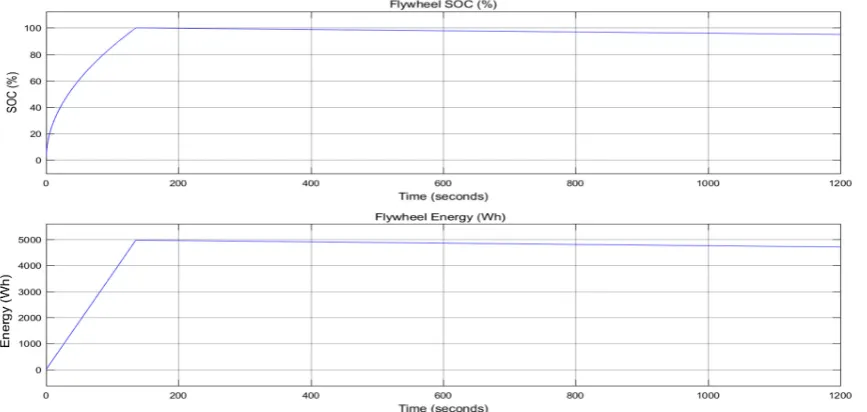
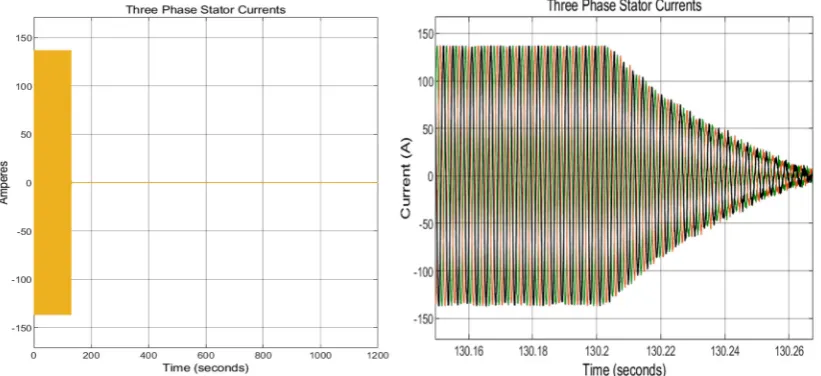
in approximately 2.17 min. Then, at = 130.2 s, the flywheel transfers to standby mode in 0.06 s
when the mechanical torque and stator currents drop to zero—Allowing the flywheel to run idle with a stored energy of 5 kWh. Figure 6 presents the results of energy storage and percentage state of charge (% SoC) of the flywheel. During the transition from charging to standby mode, three-phase currents reduce to zero smoothly with no major current spikes or waveform distortions as shown in
Figure 7. The system is left on standby mode for a long period of time ( = 130.2 − 1200 s) to show
the flywheel fast charging and idling losses.
[image:16.595.86.512.91.216.2]Figure 6. %SoC and energy stored by flywheel. Figure 5.MATLAB/Simulink model of SCIM-FESS.
5.1. Acceleration Mode
The flywheel starts to accelerate when a positive torque of 90 N·m is applied and is fully charged in approximately 2.17 min. Then, att=130.2 s, the flywheel transfers to standby mode in 0.06 s when the mechanical torque and stator currents drop to zero—Allowing the flywheel to run idle with a stored energy of 5 kWh. Figure6presents the results of energy storage and percentage state of charge (% SoC) of the flywheel. During the transition from charging to standby mode, three-phase currents reduce to zero smoothly with no major current spikes or waveform distortions as shown in Figure7. The system is left on standby mode for a long period of time (t=130.2–1200 s) to show the flywheel fast charging and idling losses.
Figure 5. MATLAB/Simulink model of SCIM-FESS.
5.1. Acceleration Mode
The flywheel starts to accelerate when a positive torque of 90 N·m is applied and is fully charged
in approximately 2.17 min. Then, at = 130.2 s, the flywheel transfers to standby mode in 0.06 s
when the mechanical torque and stator currents drop to zero—Allowing the flywheel to run idle with a stored energy of 5 kWh. Figure 6 presents the results of energy storage and percentage state of charge (% SoC) of the flywheel. During the transition from charging to standby mode, three-phase currents reduce to zero smoothly with no major current spikes or waveform distortions as shown in
Figure 7. The system is left on standby mode for a long period of time ( = 130.2 − 1200 s) to show
the flywheel fast charging and idling losses.
[image:16.595.84.518.386.592.2]Figure 7. Three phase stator currents of IM during acceleration and standby mode.
During the standby mode, the flywheel speed and SoC are decreased due to the system losses including the aerodynamic and bearing friction losses. The copper losses are zero because currents stop flowing in the stator of the IM during the standby mode due to the use of electromagnets in the stator windings. During the standby mode, the flywheel state of charge drops to 96.5% due to self-discharge giving about 215 Wh of energy losses which is 4.3% of the total stored energy. Total power loss (p.u.) in standby mode is calculated by ratio between change in kinetic energy of the flywheel
(∆ ) in Joules over the period of (∆ ) in second, with respect to the rated kinetic energy of
the flywheel ( ) in Joules, as expressed by Equation (37) [78]. Calculation of power loss gives 9.5% of total power lost over the period of 20 min.
% = (∆ )
∆ × × 100 (37)
5.2. Deceleration-Acceleration Mode at Constant Torque
[image:17.595.94.505.92.280.2]To analyse the flywheel performance during acceleration and deceleration states, different charge-discharge operations are performed during the period of 20 min. A constant torque operation is performed here to show the system responsiveness due to step torque variations that can be accounted for the load variations in real life situations. Therefore, the flywheel is initially charged for 130.2 s, then switched to standby mode for 300 s before starting to discharge due to a negative torque of 90 N·m applied at = 430 s (Figure 8). In order to test the dynamic stability of the SCIM-FESS model, multiple operations where performed by accelerating and decelerating the flywheel. At = 530 s, the flywheel starts charging for 100 seconds before the charging torque is reversed to decelerate the flywheel at = 630 s. Then the flywheel goes into the standby mode ( = 720 s) and spins with 22% of SoC and 0.4 kWh of stored energy. Different charging and discharging states of the flywheel and corresponding three-phase currents and torque waveforms are shown in Figure 8. Magnified images of three-phase stator currents and torque are shown in Figure 9 where it can be seen that IM smoothly switches from generating to motoring mode in less than 5 m s without any spikes or transients in the current waveforms showing the compliance and better performance of the machine side control system (MSC).
Figure 7.Three phase stator currents of IM during acceleration and standby mode.
During the standby mode, the flywheel speed and SoC are decreased due to the system losses including the aerodynamic and bearing friction losses. The copper losses are zero because currents stop flowing in the stator of the IM during the standby mode due to the use of electromagnets in the stator windings. During the standby mode, the flywheel state of charge drops to 96.5% due to self-discharge giving about 215 Wh of energy losses which is 4.3% of the total stored energy. Total power loss (p.u.) in standby mode is calculated by ratio between change in kinetic energy of the flywheel∆KEf lywheel
in Joules over the period of (∆t) in second, with respect to the rated kinetic energy of the flywheel (KErated FESS) in Joules, as expressed by Equation (37) [78]. Calculation of power loss gives 9.5% of total
power lost over the period of 20 min.
%Ploss=
(∆KEFESS)
∆t×KErated FESS×100 (37)
5.2. Deceleration-Acceleration Mode at Constant Torque
Figure 8. SCIM-FESS acceleration-deceleration mode: (a) %SoC of the flywheel; (b) Energy stored; (c) Mechanical torque; (d) Three phase stator currents.
(a) (b)
(c) (d)
22% SoC
Stored energy
[image:18.595.122.475.420.734.2](0.45 kWh)
Figure 8. SCIM-FESS acceleration-deceleration mode: (a) %SoC of the flywheel; (b) Energy stored; (c) Mechanical torque; (d) Three phase stator currents.Appl. Sci. 2019, 9, x 18 of 27
Figure 9. (a) Torque at t = 530 s; (b) Magnified three phase currents; (c) %SoC at t = 530 s; (d) stored energy in kWh
5.3. Deceleration-Acceleration Mode at Variable Torque
In this section the model is simulated to run at different values of torque (variable torque) for a real-life application such as transport or during variable loads on the electric grid. The flywheel is initially charged by a positive torque (90 N·m) for 50 s and then the torque is reduced to 70 N·m where the flywheel speed is reduced and the charging rate is slowed down as shown in Figure 10. At =
80 s the torque is further reduced to 50 N·m and the flywheel charges slower than before with reduced three-phase currents. It can be seen from Figures 10 and 11 that SCIM-FESS operates stably under different load conditions and the three-phase currents and speed of the flywheel comply with the torque variations during acceleration and deceleration modes.
(a) (b)
(c) (d)
5.3. Deceleration-Acceleration Mode at Variable Torque
In this section the model is simulated to run at different values of torque (variable torque) for a real-life application such as transport or during variable loads on the electric grid. The flywheel is initially charged by a positive torque (90 N·m) for 50 s and then the torque is reduced to 70 N·m where the flywheel speed is reduced and the charging rate is slowed down as shown in Figure10. Att=80 s the torque is further reduced to 50 N·m and the flywheel charges slower than before with reduced three-phase currents. It can be seen from Figures10and11that SCIM-FESS operates stably under different load conditions and the three-phase currents and speed of the flywheel comply with the torque variations during acceleration and deceleration modes.Appl. Sci. 2019, 9, x 19 of 27
Figure 10. (a)Variable torque values; (b) Three phase currents at variable toque values; (c) Magnified view of change in torque command; (d) Magnified view of currents at = 50 s.
Figure 11. (a) % SoC of the flywheel at different torque; (b) Energy stored in the flywheel at different times.
Figure 12 shows DC-link voltage at a reference value of 600 V during acceleration and deceleration at different torque values. It can be seen that voltage remains stable at a reference value of 600 V and varies ±2 V from the reference value as shown in a magnified view in Figure 12. Better regulation and stability of DC voltage under different load conditions (torques values) exhibits the better performance of the GSC controller as discussed in Section 4.1.2.
(a) (b)
(c) (d)
[image:19.595.89.510.228.563.2](a) (b)
Figure 10.(a) Variable torque values; (b) Three phase currents at variable toque values; (c) Magnified view of change in torque command; (d) Magnified view of currents att=50 s.
Appl. Sci.Figure 10. 2019,9, 4537(a)Variable torque values; (b) Three phase currents at variable toque values; (c) Magnified 19 of 26
[image:20.595.92.504.90.262.2]view of change in torque command; (d) Magnified view of currents at = 50 s.
[image:20.595.132.463.308.513.2]Figure 11. (a) % SoC of the flywheel at different torque; (b) Energy stored in the flywheel at different times.
Figure 12 shows DC-link voltage at a reference value of 600 V during acceleration and deceleration at different torque values. It can be seen that voltage remains stable at a reference value of 600 V and varies ±2 V from the reference value as shown in a magnified view in Figure 12. Better regulation and stability of DC voltage under different load conditions (torques values) exhibits the better performance of the GSC controller as discussed in Section 4.1.2.
(a) (b)
(c) (d)
(a) (b)
Figure 11. (a) % SoC of the flywheel at different torque; (b) Energy stored in the flywheel at different times.
Appl. Sci. 2019, 9, x 20 of 27
Figure 12. DC-link voltage during different states of operation and variable torque values.
5.4. SCIM-FESS Losses
The mechanical losses of the FESS are calculated based on the derived equations and the methods described in Section 3. The stray losses (eddy current and core losses) as well as the bearing and windage losses of the flywheel system as a function of the rotational speed is shown in Figure 13. Since the bearing loss is a function of the speed and the load on the bearing, and the windage loss is dependent on the speed and pressure of the flywheel rotor containment, these losses are lower in comparison to the stray losses (nearly 1.8 kW at 20,000) and are not related to the power rating of the motor/generator. For the maximum rated speed of 20,000 rpm, the bearing friction loss is approximated as 110 W and the windage loss at the atmosphere pressure level is about 90 W, giving a total of 200 W for combined windage and bearing losses. However, the system losses need to be kept at a minimum and particularly the standby losses, which is directly affected by the aerodynamic and bearing losses. Therefore, if the pressure level is kept below 10 Pa and the speed is maintained at 20,000 rpm, the windage losses will be 60% reduced as compared to the case of atmospheric pressure (Figure 13c).
Stator and rotor specific core losses of SCIM-FESS are shown in Figure 14. The core losses occur in largest fraction in the stator of the IM because at low slip, the IM operates at nearly synchronous speed and the relative speed of magnetic fields over the rotor surface are slow, therefore, rotor core losses are very small compared to stator core losses [79].
As shown in Figure 14a, the specific core losses increase exponentially with increase in speed and magnetic flux density. The stator specific core losses are not significant for values of magnetic flux density up to 1 Tesla and 3 krpm speed. However, the specific core losses in stator of IM increase significantly above 3 krpms and even at 0.648 Tesla, the power losses due to hysteresis and eddy currents in stator core of IM operating at 20 krpm is 16.48 W/kg. Rotor specific core losses of IM are shown in Figure 14b and it can be seen that rotor specific core losses increases exponentially with increase in maximum magnetic flux density. However, even at a high speed of 20 krpm, the rotor specific core losses are not significant.
Figure 12.DC-link voltage during different states of operation and variable torque values.
5.4. SCIM-FESS Losses
Figure 13. Different mechanical losses of SCIM-FESS: (a) Bearing losses due to load and speed torque; (b) Stray losses due to magnetic flux leakages; (c) Windage losses at low and high pressures;(d) Total mechanical losses.
Figure 14. Specific core losses of SCIM-FESS: (a) Stator core losses; (b) Rotor core losses.
(a) (b)
(d) (c)
(a) (b)
Figure 13.Different mechanical losses of SCIM-FESS: (a) Bearing losses due to load and speed torque; (b) Stray losses due to magnetic flux leakages; (c) Windage losses at low and high pressures;(d) Total mechanical losses.
Stator and rotor specific core losses of SCIM-FESS are shown in Figure14. The core losses occur in largest fraction in the stator of the IM because at low slip, the IM operates at nearly synchronous speed and the relative speed of magnetic fields over the rotor surface are slow, therefore, rotor core losses are very small compared to stator core losses [79].
As shown in Figure14a, the specific core losses increase exponentially with increase in speed and magnetic flux density. The stator specific core losses are not significant for values of magnetic flux density up to 1 Tesla and 3 krpm speed. However, the specific core losses in stator of IM increase significantly above 3 krpms and even at 0.648 Tesla, the power losses due to hysteresis and eddy currents in stator core of IM operating at 20 krpm is 16.48 W/kg. Rotor specific core losses of IM are shown in Figure14b and it can be seen that rotor specific core losses increases exponentially with increase in maximum magnetic flux density. However, even at a high speed of 20 krpm, the rotor specific core losses are not significant.
Appl. Sci.2019,9, 4537 21 of 26
for 50 s in charging mode and then the torque was increased to its maximum rated value of 90 N·m for 30 s. When the flywheel was at standby mode (t=80 s), there were no currents flowing through the rotor and stator windings of the IM as shown in Figure15a,b. Att=100 s, the IM operated as a generator and flywheel started discharging for 20 s until switching back to standby mode att=120 s.
Figure 13. Different mechanical losses of SCIM-FESS: (a) Bearing losses due to load and speed torque; (b) Stray losses due to magnetic flux leakages; (c) Windage losses at low and high pressures;(d) Total mechanical losses.
Figure 14. Specific core losses of SCIM-FESS: (a) Stator core losses; (b) Rotor core losses.
(a) (b)
(d) (c)
[image:22.595.91.505.159.363.2](a) (b)
Figure 14.Specific core losses of SCIM-FESS: (a) Stator core losses; (b) Rotor core losses.
Appl. Sci. 2019, 9, x 22 of 27
The copper loss in the IM is directly proportional to square of the current and is a function of current and resistance. Copper losses in the stator and rotor of the IM are measured by simulating the copper loss models (Equations (16) and (17)) in MATLAB/Simulink software. The SCIM-FESS dynamic performance was analysed at different torque magnitudes in order to demonstrate copper losses at different values of three phase currents. The system was operated with initial positive torque of 50 N·m for 50 s in charging mode and then the torque was increased to its maximum rated value
of 90 N·m for 30 s. When the flywheel was at standby mode (t = 80 s), there were no currents flowing
through the rotor and stator windings of the IM as shown in Figure 15a,b. At t = 100 s, the IM operated
as a generator and flywheel started discharging for 20 s until switching back to standby mode at t
=120 s.
The rotor and stator copper losses vary with currents as torque is varied on the shaft of the IM (Figure 15c). Stator copper losses at maximum three-phase current is 657 Watts and it decreases to zero when torque from the shaft of IM is removed. Rotor copper losses at maximum three-phase rotor current is 388 Watts and the combined total copper losses of the IM at maximum three-phase current and maximum operating torque is 1.045 kW.
Figure 15. (a) Three phase rotor currents; (b) Three phase stator currents; (c) Torque commands; (d) Copper losses in rotor and stator of IM.
As a comparison to the loss model of the SCIM-FESS presented in this research, the performance analysis of a PMSM-FESS for the same system rating (100 kW, 5 kWh and 10–20 krpm) is presented in reference [29]. It is shown that the IM draws high inrush current at the starting but operates normally during the transition periods between charge-discharge states. For the case of PMSM, it starts normally with no major inrush currents but has higher standby losses. In contrary, IM do not use permanent magnets and has not standby electrical losses.
(a) (b)
(d) (c)
[image:22.595.89.511.391.728.2]The rotor and stator copper losses vary with currents as torque is varied on the shaft of the IM (Figure15c). Stator copper losses at maximum three-phase current is 657 Watts and it decreases to zero when torque from the shaft of IM is removed. Rotor copper losses at maximum three-phase rotor current is 388 Watts and the combined total copper losses of the IM at maximum three-phase current and maximum operating torque is 1.045 kW.
As a comparison to the loss model of the SCIM-FESS presented in this research, the performance analysis of a PMSM-FESS for the same system rating (100 kW, 5 kWh and 10–20 krpm) is presented in reference [29]. It is shown that the IM draws high inrush current at the starting but operates normally during the transition periods between charge-discharge states. For the case of PMSM, it starts normally with no major inrush currents but has higher standby losses. In contrary, IM do not use permanent magnets and has not standby electrical losses.
6. Discussion and Conclusions
This paper presented the analysis of the dynamic performance of a squirrel-cage induction machine integrated to a flywheel storage with a developed model in MATLAB/Simulink. The structure of the control system as well as the comprehensive loss model consisted of the electrical, mechanical and power electronics losses were also discussed and embedded in the model. A detailed simulation model of a 100 kW IM drive was presented and analysed in different states of charging, discharging and standby modes.
The presented results show the analysis of an induction machine driven flywheel storage system during different modes of operation including constant and variable torque conditions. The dynamic performance of the system was analysed for the two general cases of constant power and constant torque operations and the results of the analysis were presented. The SCIM-FESS was operated within a speed range of 10–20 krpm at a shaft torque of 90 N·m storing 5 kWh of energy in 2.17 min. The presented system with the proposed control system and parameters of the machine, can store more energy at higher speed (more than 20 krpm) at the expense of higher windage losses. When the torque on the flywheel is zero during standby mode, an energy loss of 215 Wh occurs in a period of approximately 18 min where the flywheel speed reduces to 19,480 rpm due to the windage effect and frictional component of the bearing torque. The standby losses of the system can be reduced by maintaining a low vacuum and using a better technology for the bearing system such as magnetic bearing but this will increase the cost of the system. Aerodynamic drag of the rotor can be reduced by housing the rotor in low a vacuum chamber, and can reduce the losses considerably as shown in Figure13. Copper and iron losses in the stator of IM are negligible during standby mode as no currents flow in the stator of the IM (Figure15) and, therefore, no magnetic field exists due to use of electromagnets in the stator windings. This is a significant advantage of IM over PMSM as it reduces total losses of the system providing better efficiency.
Stable operation of the system implies that the use of the proposed control system in IM drive provides better performance and quick reversal electromagnetic torque during the transition from generating to motoring mode and vice versa. Operation scenarios of FESS presented in Sections5.2
and5.3are the benchmarks for flywheel applications in transport and in an electric grid under different load conditions. The presented results show a realistic system with drag losses working stably in different conditions which justifies the proper working of control systems proposed in the paper. Also, the SCIM-FESS can be explored and analysed for use with a renewable energy source and a diesel generator set which can be used for energy management and ride through applications. This can improve the efficiency of the intermittent renewable energy source and save fuel costs of the associated diesel generator set.
![Table 1. Advantages and drawbacks of commonly used electrical machines in FESS [13,25,47,52,53].](https://thumb-us.123doks.com/thumbv2/123dok_us/1355686.89120/7.595.81.511.105.511/table-advantages-drawbacks-commonly-used-electrical-machines-fess.webp)
![Table 3. Manufacturer’s loss data for M470-50HP electrical steel. Adapted with permission from [66],Cogent Power Inc., 2019.](https://thumb-us.123doks.com/thumbv2/123dok_us/1355686.89120/10.595.95.501.554.687/table-manufacturer-electrical-steel-adapted-permission-cogent-power.webp)
![Table 4. Values of z and y. Adapted with permission from [69], Taylor and Francis Group LLC, 2019.](https://thumb-us.123doks.com/thumbv2/123dok_us/1355686.89120/12.595.84.511.231.297/table-values-adapted-permission-taylor-francis-group-llc.webp)