SMART CAR SEAT
NURHIDAYAH ABDUL MALEK
This report is submitted in partial fulfillment of the requirements for the award of Bachelor of Electronic Engineering (Industrial Electronics) With Honours
Faculty of Electronic and Computer Engineering Universiti Teknikal Malaysia Melaka
UNIVERSTI TEKNIKAL MALAYSIA MELAKA
FAKULTI KEJURUTERAAN ELEKTRONIK DAN KEJURUTERAAN KOMPUTER
BORANG PENGESAHAN STATUS LAPORAN
PROJEK SARJANA MUDA II
Tajuk Projek : SMART CAR SEAT
Sesi Pengajian : 2005/2009
Saya NURHIDAYAH BINTI ABDUL MALEK mengaku membenarkan Laporan Projek Sarjana Muda ini disimpan di Perpustakaan dengan syarat-syarat kegunaan seperti berikut:
1. Laporan adalah hakmilik Universiti Teknikal Malaysia Melaka.
2. Perpustakaan dibenarkan membuat salinan untuk tujuan pengajian sahaja.
3. Perpustakaan dibenarkan membuat salinan laporan ini sebagai bahan pertukaran antara institusi pengajian tinggi.
4. Sila tandakan ( √ ) :
SULIT*
(Mengandungi maklumat yang berdarjah keselamatan atau kepentingan Malaysia seperti yang termaktub di dalam AKTA RAHSIA RASMI 1972)
TERHAD* (Mengandungi maklumat terhad yang telah ditentukan oleh
organisasi/badan di mana penyelidikan dijalankan)
TIDAK TERHAD
Disahkan oleh:
__________________________ ___________________________________
(TANDATANGAN PENULIS) (COP DAN TANDATANGAN PENYELIA)
Alamat Tetap: B-7-1, VISTA MSN, KOMPLEKS SUKAN NEGARA,
BUKIT JALIL,
57000,SRI PETALING, KUALA LUMPUR.
Tarikh: 30 APRIL 2009 Tarikh: 30 APRIL 2009
iii
“I hereby declare that this report is the result of my own work except for quotes as cited in the references.”
Signature : ………..
Author : NURHIDAYAH BINTI ABDUL MALEK
iv
“I hereby declare that I have read this report and in my opinion this report is sufficient in terms of the scope and quality for the award of Bachelor of Electronic
Engineering (Industrial Electronics) With Honours.”
Signature : ………..
Supervisor‟s name : MRS. HAZURA BINTI HAROON
v
vi
ACKNOWLEDGEMENT
vii
ABSTRACT
viii
ABSTRAK
ix
CONTENT
CHAPTER TITLE PAGE
PROJECT TITLE i
DECLARATION iii
DEDICATION v
ACKNOWLEDGEMENT vi
ABSTRACT vii
ABSTRAK viii
CONTENT ix
LIST OF TABLES xii
LIST OF FIGURES xiii
APPENDICES xv
I INTRODUCTION 1.0 Overview 1
1.1 Project Objectives 1
1.2 Problem Statement 2
1.3 Scope of Project 2
1.4 Project Methodology 3
1.5 Report Structure 5
II LITERATURE REVIEW 2.1 Recent Projects 6
2.1.1 Hyperthermia Prevention Child Car Seat 6
x
2.1.2 Smart Car Seat 8
2.1.2.1 Description of Block Diagram 9
2.1.3 Smart Car Seat 10
2.1.3.1 Description of Block Diagram 11
2.2 Microcontroller 12
2.3 Passive Infrared Sensor 14
2.4 LM 35 15
2.5 AND Gate 16
2.6 RF Module 18
2.6.1 RF Transmitter 19
2.6.2 RF Receiver 21
2.6.3 Antenna 23
III METHODOLOGY 3.0 Overview 24
3.1 Literature Review 24
3.2 Circuit Design 24
3.3.1 Flow Chart 25
3.3.2 Block Diagram 26
3.3.2.1 Car seat block diagram 27
3.3.2.2 Receiver block diagram 27
3.3.2.3 Description of block diagram 28
IV RESULT AND DISCUSSION 4.1 Result 30
4.1.1 Testing 30
4.1.1.1 Motion Detector 30
4.1.1.2 Temperature Sensor (LM35) 32
4.1.1.3 RF Module 33
xi
4.1.2.1 Transmitter Circuit 34
4.1.2.2 Receiver Circuit 35
4.1.3 Hardware Part 36
4.1.3.1 The Schematic Circuit Diagram 36 4.1.3.1.1 Car Seat Schematic Diagram 36 4.1.3.1.2 Receiver Schematic Diagram 37 4.1.3.2 Car Seat Circuit (Transmitter) 38
4.1.3.3 Receiver Circuit 42
4.1.4 Project Prototype 42
4.1.5 Circuit Overview 43
4.2 Discussion 46
V CONCLUSION
5.0 Conclusion 48
5.1 Future Recommendation 48
xii
LIST OF TABLES
NO TITLE PAGE
2.1 The Function table of AND Logic 17
2.2 Operating Condition 17
2.3 Specification of Transmitter Module 20
2.4 Transmitter Label‟s Description 21
2.5 Specifications of Receiver Module 22
xiii
LIST OF FIGURES
NO TITLE PAGE
1.1 Flow Chart of Project Methodology 4
2.1 Block diagram 1 7
2.2 Block Diagram 2 9
2.3 Block diagram of Main System 11
2.4 Block Diagram of Keychain System 11
2.5 The PIC16F876A 13
2.6 Passive Infrared Sensor (PIR) 14
2.7 PIR pin 15
2.8 LM 35 15
2.9 Package used 16
2.10 Connection Diagram 18
2.11 Dimension of IC 18
2.12 Transmitter Module 20
2.13 Receiver Module 22
3.1 Flow chart of project (Transmitter) 25
3.2 Flow chart of project (Receiver) 26
3.3 Car Seat Block Diagram 27
3.4 Receiver Block Diagram 27
4.1 The output voltage of PIR when a motion detected 31 4.2 The output voltage of LM 35 when it detects high heat 32
4.3 Basic Centigrade Temperature Sensor 32
4.4 RF Module Testing 33
4.5 The simulation result for transmitter 34
xiv
4.7 The transmitter circuit 37
4.8 The receiver circuit 38
4.9 The transmitter circuit testing 39
4.10 The LED indicate that a motion has been detected 40 4.11 The LED indicates that both of the sensors are high. 40 4.12 The green LED near the transmitter indicate that the transmitter 41
send a signal
4.13 The LED turns on and the buzzer beeps 42
5.4 Project Prototype 43
5.5 Car seat circuit overview 44
xv
APPENDICES
NO TITLE PAGE
A Transmitter Program Code 51
CHAPTER I
INTRODUCTION
1.0 Overview
The purpose of this project is to design a device to help ensure the safety of children especially infants that are accidentally left in a car. This project includes a system for alerting someone that a child is left in a safety seat in a vehicle at the temperature is raising. A motion detector is used in order detect the presence of the child while the temperature circuit monitors the temperature levels in the car to determine if the child is in danger. The PIC circuit is used to combine both circuits. If motion is detected and the temperature reached the specify value, the RF transmitter will transmit a signal to RF receiver to remind them that a child is left in the car by alarm sound. The RF receiver is attached to the car keys so that it will alert parents to prevent any danger occur.
1.1 Project Objectives
The objectives of this project are:
a) To design a circuit that will detect a motion in a car.
2
c) To design a circuit that will alert someone from risk the infant.
1.2 Problem Statement
Each year we shocked by cases that involved innocent children died after being left inside a hot vehicle. Statistics shows that total number of United State of America (U.S.) hyperthermia deaths of children left in cars for 2007 and 2008 are 35 and 42 respectively [1]. This tragedy most occurred because of carelessness by leaving them alone accidentally in a vehicle for a long time. Heat is just another reason not to leave them since infants are particularly susceptible dehydration and may quickly suffer a deadly heat stroke (hyperthermia). The large numbers of children die in those types of conditions being an inspiration of this invention.
1.3 Scope of Project
The scopes of this project are divided into two block diagrams which are car seat block diagram and receiver block diagram. The circuits involve are:
a) Car Seat (Transmitter circuit.)
i. Passive Infrared Sensor (PIR) is use for motion detector circuit to detect the presence of the child in the car seat
ii. LM35 is use as the temperature sensor to detect if the temperature reached 35°C.
iii. An AND gate IC is use to determine the condition is high when both inputs are high.
3
b) Keychain (Receiver circuit)
i. Receiver (RF Module) receives signal from transmitter by using RF Receiver Module.
ii. Buzzer is use to alert and indicate about their child to the parents. .
c) PIC circuit
Two PIC16F876A microcontrollers are uses to combine both sensors and to receive signal for the keychain circuit by using C language programming.
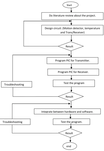
1.4 Project Methodology
4
Figure 1.1 Flow Chart of Project Methodology
Do literature review about the project.
Integrate between hardware and software.
Start
Test the program. Troubleshooting
Result
end
Test the program
Design circuit: (Motion detector, temperature and Trans/Receiver)
Result
Program PIC for Transmitter.
Result Troubleshooting
5
1.5 Report Structure
This report contains of five main chapters. The titles of each chapter are Introduction, Literature Review, Project Methodology, Results and Discussion and Conclusion.
In Chapter 1, this report starts with the brief introduction of the project. The objectives, scope of project, problem statement and methodology of the project are stated.
In Chapter 2, literature review of the project is explained. The theories of the devices and other components such as sensors and microcontroller that are related to this project are stated.
In Chapter 3, the methodology and the process of the project will be discussed. Also including the advantages of the method and components selected.
In Chapter 4, results of finding the project are recorded followed by discussion of the project.
CHAPTER II
LITERATURE REVIEW
2.1 Recent Projects
2.1.1 Hyperthermia Prevention Child Car Seat
7
Figure 2.1 Block diagram 1
2.1.1.1 Description of block diagram:
a) Sensors
This block contains the flex sensors used to detect the presence of a child; the thermistor based voltage divider used to detect a dangerous temperature, and 2 analog comparator circuits that send high logic levels to the microcontroller when the corresponding condition is true. This part is only present on the car seat [2].
b) Serial Interface
8
c) RF interface
This block contains the antenna, LINX chip, and a voltage divider used to limit the range of transmission/reception. This will be a transmitter chip on the car seat, and a receiver chip on the key chain. This interface will be connected to a UART on the microcontroller [2].
d) Microcontroller
This block contains our microcontroller, and any circuits needed to support programming and debugging of it [2].
e) Buzzer/Lights
This block contains whatever our attention-getter is. On the keychain this will be a piezoelectric buzzer, on the car seat this may be the horn and headlight relays of the car. This is driven off of a GPIO pin of the microcontroller [2].
f) Power
This block contains a battery and a circuit for charging it from the cigarette lighter on the car seat, and a pair of watch batteries on the key chain [2].
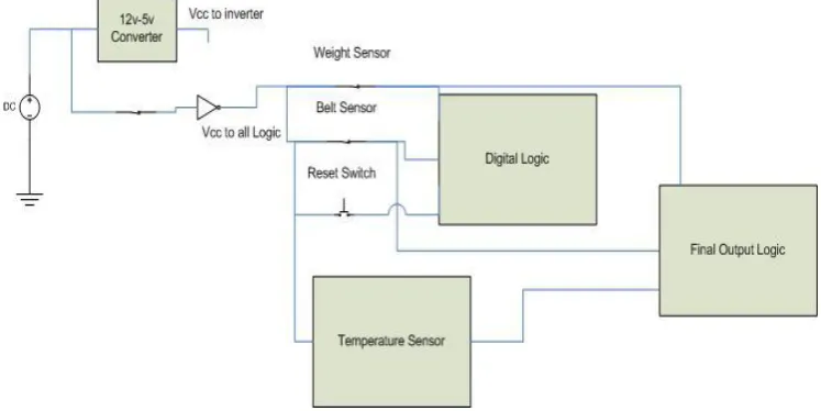
2.1.2 Smart Car Seat
9
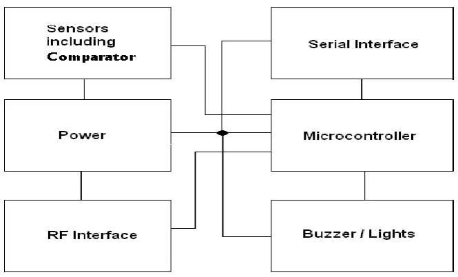
Figure 2.2 Block Diagram 2
2.1.2.1Description of block diagram:
a) Temperature Sensor
The temperature sensor uses a temperature sensitive transistor output that goes through a voltage divider and is sent into a logic circuit [3].
b) Weight sensor
The weight sensor will use a simple mechanical method of separating insulated bolts by springs so that when a weight is placed on the seat, the springs will compress and the bolts will touch, creating an electrical connection [3].