International Journal of Innovative Technology and Exploring Engineering (IJITEE) ISSN: 2278-3075, Volume-9 Issue-1, November 2019
Abstract: This paper presents Modeling and Simulation of Two-Dimensional Position Sensitive Detector (PSD) using MATLAB. PSD is an Optical Position Sensor (OPS) that can measure a position of a radiation spot in one or two-dimensions on a sensor surface. Unlike discrete elements such as Charge-Coupled Device (CCD), it provides continuous position data, features high position resolution and high-speed response which give this paper its importance. The sensor used consists of two-dimensional array of photodiodes. The sensor has four output photocurrents that change according to the position of incident radiation on the surface. The work is divided into three parts of Modeling and Simulation; the first part is a single photodiode, Second part is one-dimensional array of photodiodes and the third one is two-dimensional array of photodiodes. The tool used to do the simulation is MATLAB software because it is professional and accurate tool, it has photodiode element and it is possible to control the beam of incident light. This research can be useful for Acquisition; Pointing and Tracking (APT) systems where this sensor will give the necessary data to do tracking operation. Proteus software was also been used as a secondary tool.
Keyword: MATLAB, Photocurrent, Photodiode, Position Sensitive Detector (PSD).
I. INTRODUCTION
Position-sensitive detectors (PSDs) are commonly used for optical position measurement. It is a position sensor that detects a light spot on the photosensitive area by using surface resistance, because it is lateral-effect photodiodes (not segmented), and provides high resolution continuous electrical signals with fast response. These detectors can be used to measure extremely small changes in the position of an incident light beam and are used for nulling, centering, detecting and measuring position displacements.
This sensor plays a major role in Acquisition; Pointing and Tracking (APT) systems, where it is used to align a free-space optical (FSO) transmitter and receiver to attain line-of-sight, which is required for effective operation of FSO communications.
The outputs of PSD are four currents signals, the value of these signals change according to the position of the incident beam.by processing these signals we can determine the exact position and then take the appropriate action [1][2].
Revised Manuscript Received on November 06, 2019.
Shaher Dwik PG Scholar, Department of ECE, VelTech Rangarajan Dr.Sagunthala R&D Institute of Science and Technology, Chennai, India. Email: [email protected]
Natarajan Somasundaram, Department of ECE, VelTech Rangarajan Dr.Sagunthala R&D Institute of Science and Technology, Chennai, India. Email: [email protected]
II. MODEL DEFINITION
As PSD consists of two-dimensional of photodiodes we divided our work to three levels of simulation first level is a single photodiode, second one is one-dimensional array of photodiodes and the third one is two-dimensional array of photodiodes.
A. Photodiode
A photodiode is a semiconductor device which can convert light into an electrical current. The current is generated when photodiode absorbs the photons. The photocurrent increases according to the power of the incident radiation that as the power of radiation is higher the photocurrent generated will be more. A photodiode is designed to be operated in reverse bias. The equivalent circuit of a photodiode is shown in figure (1):
Using the above equivalent circuit, the output current ( ) is given by equation (1) [3], [4]:
(1) Where;
: photocurrent (generated by incident radiation). : Diode current.
The driving circuit used to measure the actual photocurrent is illustrated in figure (2):
Modeling and Simulation of Two-Dimensional
Position Sensitive Detector (PSD) Sensor
Shaher Dwik, Natarajan Somasundaram
Modeling and Simulation of Two-Dimensional Position Sensitive Detector (PSD) Sensor
B. One-dimensional array of photodiodes
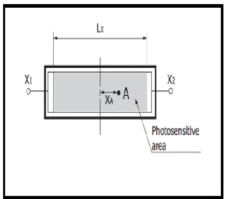
Figure (3) illustrates the photosensitive area (one-dimensional PSD):
Since the resistance of the surface is uniform, the current output from the two poles is inversely proportional to the distance from the point of radiation to the poles. The distance of the two electrodes is and the output light current of the electrodes ( ) and ( ) are respectively and and the incident position conversion formula is calculated from the following equation (Forexample (A)) [3], [4]:
= · (2)
C. Two-dimensional array of photodiodes
Figure (4) illustrates the photosensitive area (two- dimensional PSD):
We noticed that this case is similar to the one-dimensional with a difference that we have two axis of coordinates X and Y instead of only X.
The incident position conversion formula is calculated from the following equations (Forexample (A)) [3], [5], [6]:
= · (3) = · (4)
III. SIMULATION
In this research we also divided the simulation to three levels as above and we used to do this simulation two software tools; Proteus and Matlab.
Proteus is an electronic circuit design software which includes a schematic capture, simulation and PCB (Printed Circuit Board) Layout modules. Proteus is very simple to use and it has wide range of components in its libraries.
MATLAB is a programming platform designed specifically for engineers and scientists produced by MathWorks. The core of MATLAB is the MATLAB language, a matrix-based language allowing the most natural expression of computational mathematics. Typical uses include:
Math and computation.
Algorithm development.
Modeling, simulation, and prototyping.
Data analysis, exploration, and visualization.
Scientific and engineering graphics.
Application development, including Graphical User Interface building [7].
MATLAB is considered very professional, academic and accurate software tool.
A. Single diode simulation
[image:2.595.73.232.69.254.2]Figure (5) illustrates the circuit used to simulate a single photodiode using Matlab. It is a simple circuit, mainly consists of voltage source, a photodiode connected on series with current sensor which is connected to display tool. We control the light beam by the incident radiation block which it is a constant. In the following the description of the blocks used:
Fig.2: circuit used to measure the actual photocurrent
Fig.3: photosensitive area (one-dimensional PSD)
[image:2.595.58.280.359.553.2]International Journal of Innovative Technology and Exploring Engineering (IJITEE) ISSN: 2278-3075, Volume-9 Issue-1, November 2019
Photodiode: The Photodiode block represents a photodiode
as a controlled current source and an exponential diode connected in parallel. The controlled current source produces a current that is proportional to the radiant flux density.
Solver Configuration: For simulation each physical network
that represented by a connected Simscape block diagram requires solver settings information. The Solver Configuration block is used to specify the solver parameters that your model needs before you can begin simulation.
PS Constant: The PS Constant block generates a physical
signal of a constant value. You determine the value of the signal as the Constant parameter.
Current Sensor: This block represents an ideal current sensor,
which it is, a device that converts current measured into a physical signal proportional to the current.
PS-Simulink Converter: It converts a physical signal into a
Simulink output signal. We use this block to connect outputs of a Physical Network diagram to Simulink scopes or other Simulink blocks.
Scope: Display signals generated during simulation [7].
B. Second part of simulation (one-dimensional array)
In this part we formed one-dimensional array of photodiodes and measured the output currents at the ends of the array that we have two photocurrents generated X1 and X2. Our array consists of three photodiodes their cathodes are connected to one point. We will do simulation in three cases each time we will assume that the incident radiation fell on one of the three photodiodes (spot). First we did simulation using Proteus because it is much easier and less complicated to use but Proteus does not have photodiode element so we used instead of it a current source. Figure (6) illustrates simulation of 1D array using Proteus. We did simulation in three cases each case presents different state of position of incident radiation. After simulation using Proteus we moved to do the same but using MATLAB. Figure (7) illustrates modeling 1D array of photodiodes using MATLAB:
Fig.5: circuit used to simulate a single photodiode using MATLAB
Fig.6: 1D array simulation using Proteus
b a
c
Modeling and Simulation of Two-Dimensional Position Sensitive Detector (PSD) Sensor
C. Third part of simulation (two-dimensional array)
After finishing simulation for 1D array we moved to do simulation for 2D array. We assumed that the 2D array consists of (3×3) photodiode then there are nine possibilities that can incident radiation falls but in our research we only will discuss three possibilities and the rest are the same. As in the previous case first we did simulation using Proteus software. Figure (8) illustrates the circuit used to simulate 2D array of photodiode using Proteus. Next we did simulation using MATLAB. Figure (9) illustrate simulation of 2D array using MATLAB that each figure assumes different position of incident radiation. For example, figure (9.a) assumes the incident radiation in the center which means photodiode 5 is active, Figure (9.b) assumes photodiode 8 is active and figure (9.c) assumes photodiode 3 is active, then as we mentioned previously according to our circuit we have nine possibilities of position of incident radiation but we only showed three for explaining.
Fig.7: 1D array simulation using MATLAB
a b
c
International Journal of Innovative Technology and Exploring Engineering (IJITEE) ISSN: 2278-3075, Volume-9 Issue-1, November 2019
IV. RESULTS
In this part we will discuss the results we obtained from the modeling and simulation we did as shown in previous sections.
Fig.8: 2D array simulation using Proteus
c
b
c
b
a
Modeling and Simulation of Two-Dimensional Position Sensitive Detector (PSD) Sensor
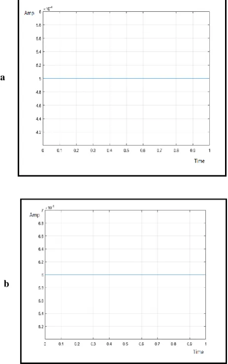
A. Single photodiode
Circuit used to simulate a single photodiode is shown in figure (5) which simulates how photocurrent changes according to incident radiation. We can change the incident radiation by changing the value of PS Constant block which it will be multiplied by the value of Photodiode whit it is initially (5 uA). Suppose the value of PS Constant is 100 then the photocurrent value will be 500 uA, and when it is 120 the photocurrent value will be 600 uA and so on. Figure (10) illustrates how photocurrent increases from 500 uA (as figure 10.a) to 600 uA (as figure 10.b) by increasing incident radiation:
B. One-dimensional array of photodiode
We did simulation for 1D array by using both Proteus and MATLAB. We assumed the total current generated is 500 uA.
In Proteus:
From figure (6) we can see results of simulation using Proteus. In case (a) we notice when the incident radiation falls on center spot (A) then both currents X1 and X2 are equal X1=X2=250uA. In case (b) when incident radiation falls on right side spot (B) we notice X1=375uA is greater than X2=125uA. By the same in case (c) spot (C) we notice X2=375uA is greater than X1=125uA.
In MATLAB:
Figure (11) illustrates the values of X1 and X2 when incident radiation falls on center (spot A) which they are equal
X1=X2=250uAwhich is compatible with case shown in figure (7.a):
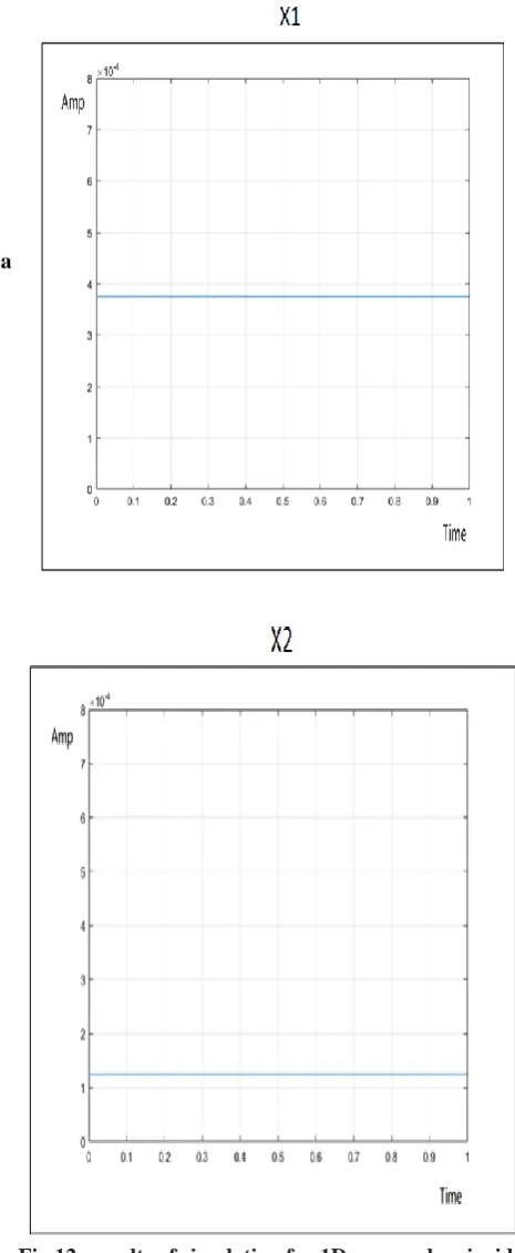
[image:6.595.316.551.81.554.2]Figure (12) illustrates the values of X1 and X2 when incident radiation is shifted to the right of center spot (B) where X1=375uA is greater than X2=125uA which is compatible with case shown in figure (7.b):
[image:6.595.317.543.89.321.2]Fig.10: results of simulation for a single photodiode using MATLAB
Fig.11: results of simulation for 1D array when incident radiation is on spot (A) using MATLAB
b a
[image:6.595.43.275.196.566.2] [image:6.595.318.549.332.549.2]International Journal of Innovative Technology and Exploring Engineering (IJITEE) ISSN: 2278-3075, Volume-9 Issue-1, November 2019
Figure (13) illustrates the values of X1 and X2 when incident radiation is shifted to the left of center spot (C) where X2=375uA is greater than X1=125uAwhich is compatible with case shown in figure (7.c):
C. Two-dimensional array of photodiode
As in 1D array we also did simulation using both Proteus and MATLAB.
In Proteus:
From figure (8) we can see results of simulation using Proteus. In case (a) we notice when the incident radiation falls on center spot (A) then all currents X1, X2, Y1 and Y2 are equal X1=X2=Y1=Y2=250uA. In case (b) when incident radiation falls on spot (B) then the values of currents are as following: X1=187uA, X2=187uA Y1=98.2uA and Y2=527uA. By the same in case (c) when incident radiation falls on spot (C) the values of currents are as following: X1=71.4uA, X2=429uA Y1=429uA and Y2=71.4uA.
[image:7.595.43.276.55.621.2]In MATLAB:
[image:7.595.41.275.57.326.2]Fig.12: results of simulation for 1D array when incident radiation is on spot (B) using MATLAB
Fig.13: results of simulation for 1D array when incident radiation is on spot (C) using MATLAB
b a
[image:7.595.319.553.119.502.2]Modeling and Simulation of Two-Dimensional Position Sensitive Detector (PSD) Sensor
Figure (14) illustrates the values of X1, X2, Y1 and Y2 when incident radiation falls on center spot (A) which they are all equal X1=X2=Y1=Y2=250uA which is compatible with case shown in figure (9.a):
[image:8.595.309.530.51.287.2]Figure (15) illustrates the values of currents X1, X2, Y1 and Y2when incident radiation falls on spot (B) which they are as following: X1= X2=187uA, Y1=98uA and Y2=527uA which is compatible with case shown in figure (9.b):
Fig.14: results of simulation for 2D array when incident radiation is on spot (A) using MATLAB
a
b
d
c
[image:8.595.56.261.97.762.2] [image:8.595.322.540.400.664.2]International Journal of Innovative Technology and Exploring Engineering (IJITEE) ISSN: 2278-3075, Volume-9 Issue-1, November 2019
[image:9.595.48.277.56.721.2]Figure (16) illustrates the values of currents X1, X2, Y1 and Y2 when incident radiation falls on spot (C) which they are as following: X1=Y2=71.4uA and X2=Y1=429uA which is compatible with case shown in figure (9.c):
Fig.15: results of simulation for 2D array when incident radiation is on spot (B) using MATLAB
b
c
d
a
[image:9.595.315.555.100.687.2]Modeling and Simulation of Two-Dimensional Position Sensitive Detector (PSD) Sensor
In table I we summarize the results of 2D array we obtained by simulation which it imitated different potential positions (A, B and C) which they are illustrated in figure 9:
position
A 250uA 250uA 250uA 250uA B 187uA 187uA 98uA 527uA C 71.4uA 429uA 429uA 71.4uA As we mentioned before there are nine possibilities of spots but in this research we only discussed three potential spots of incident radiation and the rest are similar and only the values of currents will change according to the position of the incident radiation.
V. CONCLUSION
Thus, we did modeling and simulation of Position Sensitive Detector (PSD) using Proteus and MATLAB which is considered an academic and accurate software tool. We noticed that by changing the position of incident radiation the generated currents will also change according to the position
which is the point that the sensor based on. This research can be used in Acquisition; Pointing and Tracking (APT) systems. This is consider first step in these systems which it is
obtaining of signals and the next step must be signal conditioning like converting current to voltage and then amplifying.
REFERENCES
1. M.F.Heweage, X.Wen and A. Eldamarawy, “Developing Laser Spot
Position Determination Circuit Modeling and Measurements with a Quad Detector”, International Journal of Modelling and Optimization, Vol. 6, No. 6, pp.310-316, December 2016.
2. Y.Kaymak et.al, “A Survey on Acquisition, Tracking, and Pointing
Mechanisms for Mobile Free-Space Optical Communications”, IEEE Communications Surveys & Tutorials, Vol. 20, No. 2, pp.1104-1123, 2018.
3. Silicon Photodiode Handbook. [available online]:
https://www.hamamatsu.com/resources/pdf/ssd/e02_handbook_si_pho todiode.pdf
4. L.Lin, Z.Sitong, T.Luyang and W.Dong, “Sun sensor design and test of
a micro satellite”, Journal of Measurements in Engineering”, Vol. 4, No. 3, pp.148-155, September 2016.
5. I.A.Ivan, M.Ardeleanu and G.J.Laurent, “High Dynamics and Precision
Optical Measurement Using a Position Sensitive Detector (PSD) in Reflection-Mode: Application to 2D Object Tracking over a Smart Surface”, Sensors, Vol. 12, pp.16771-16784, 2012.
6. L.Xiaohong et.al, “Design of Double PSDs mounting plate on the
tracing measurement system”, Journal of Advanced Mechanical Design, Systems, and Manufacturing, Vol. 11, No. 1, pp.1-10, January 2017.
7. https://mathworks.com/
AUTHORS PROFILE
Shaher Dwik received his Bachelor in Electronic Systems Engineering from University of Aleppo, Aleppo, Syria in 2017. His research interest includes embedded systems, optoelectronics and optical devices. He is perusing Master of Embedded Systems & Technology from VelTech Rangarajan Dr.Sagunthala R&D Institute of Science and Technology, Chennai, India.
Natarajan Somasundaram received his Bachelor in Electronics and Communication Engineering from Bharathiar University, India in 2002, M.E. in Embedded System Technologies from Anna University, Chennai in 2005 and Ph.D. in 2009. His research interest includes reconfigurable embedded systems, VLSI Design and Light Communication Architectures. He is currently a Professor in Department of ECE, VelTech Rangarajan Dr.Sagunthala R&D Institute of Science and Technology, Chennai, India.
Fig.16: results of simulation for 2D array when incident radiation is on spot (C) using MATLAB
d c