Abstract: This paper presents an overview of design, modeling and simulation of MEMS pressure sensor is using COMSOL Multiphysics V4.3b. An attempt has been made to achieve high sensitivity by providing different structures for membrane (Circular, square, rectangle & triangle) with uniform surface area and thickness. Further, simulations have been carried out with various loads ranging from 0.1 to 1MPa assigning three materials viz., InP, GaAs and Silicon. From the analyses of simulation results, it has been observed that the pressure sensor with circular membrane provided InP material found to exhibit more deformation and high sensitivity of 17.3×10⁻¹² for 10 µm thickness
and 50.8×10⁻¹² for 7 µm thickness. The reasons for enhancement in the sensitivity are discussed in detail as function of input load, dimensional changes of diaphragm and materials addition. These studies are highly useful to check and compute pressure in various industrial and environmental conditions.
Index Terms: Pressure sensor; Displacement; Diaphragm; Stress; COMSOL.
I. INTRODUCTION
There has been growing demand for investigations to improve the sensitivity of MEMS based pressure sensor for numerous industrial applications due to their superior features such as low power consumption, high deformation and high sensitivity. MEMS based pressure sensors are mostly used in airplanes, gas turbine engine, submarines, automobiles and biomedical devices. The key parameters of pressure sensors are sensitivity, repeatability and stability. MEMS pressure sensors work on the principle of the mechanical deformation of a thin diaphragm due to the pressure exerted by the contact medium. The accurate measurement of pressure has become vital in variety of industrial applications. There are different pressure sensing approaches which puts limitations on sensitivity due to many reasons these are the effect of variations in one variable by keeping other variables constant may not be very effective as the variable may be interdependent. In a practical situation, the variables are-often related and move together e.g. the selling price and the expected sales volume are interrelated. These drawbacks lead to sensing of pressure with some errors which really needs to be addressed. In general, pressure sensor with a diaphragm will enable to measure the displacement in response to the load applied. It is also worth mentioning that the shape of the diaphragm is crucial in determining the sensitivity of pressure sensor. Various
Revised Manuscript Received on November 05, 2019.
Satyanarayana Talam,Dept. of EIE, Lakireddy Bali Reddy College of Engineering (A), Mylavaram-521230, Krishna Dt., A.P., India.
Rambabu Busia, Dept. of EIE, Lakireddy Bali Reddy College of Engineering (A), Mylavaram-521230, Krishna Dt., A. P., India.
email:[email protected]
Supraja.V.N.La, Dept. of EIE, Lakireddy Bali Reddy College of Engineering (A), Mylavaram-521230, Krishna Dt., A. P, India.
attempts have been made to improve the sensitivity of pressure sensor by means of shape and dimensions of diaphragm along with change of suitable materials. Lot of research has been carried out along the proposed line of investigation. Balaji et.al [1] reported the distinctions among various diaphragm shapes with respect to linearity and burst strength. Finite Element Analysis (FEA) with Conventorware software has been used for the distribution of stress on the diaphragm. It was found that the circular diaphragm gives good linearity as well as higher burst stress acceptance characteristics. Suja K J.et.al [2] has been carried out various performance parameters of pressure sensor such as deflection, stress and voltage sensitivities etc. They reported that SiO2 based pressure sensors are suitable for high pressure
ranges with better sensitivity and conventional pressure sensors are utilized for low pressure ranges. T.Shanmuganantham et.al [3-4] discussed about the sensitivity of MEMS pressure sensor based on diaphragms of different shapes using INTELLISUITE software tool. They reported that the sensitivity is absolutely depends on dimensions and suitable material. They also mentioned that high sensitivity is realized by thin or large membrane which further creates unstable sensor structure. Berns.A.et.al [5] discussed that the contrast to pressure sensor arrays in literature this array is highly sensitive and can be flush mounted on top of a cylinder without using pin holes and flexible tubes. Employing silicon-on-insulator (SOI) technology and deep silicon etching the sensors developed achieve a pressure resolution of 0.5 Pa. Three different types of sensors, featuring a diaphragm thickness of 3m and diaphragm sizes of 500 m, 700m, and 900 m (square diaphragm), have been fabricated and characterized. Tingzhong Xu et. al [6] provides a systematic analysis of the influence of the diaphragm stiffness distribution on the stress concentration characteristics of a pressure sensing chip, which provides a guideline for diaphragm design for piezoresistive pressure sensing chips. Based on our systematic analysis, the optimization method and distribution patterns of peninsula-island structure were also discussed to improve the performance of sensing chips. It was concluded that pressure sensors with the proposed bossed diaphragms had excellent sensitivity, linearity and stability. The pressure sensors with the proposed diaphragm are potentially a better choice to measure ultra-low pressures in the fields of biomedical instruments, smart homes and aerodynamics. A. Nallathambi et.al reported novel high sensitivity and linear 0-1MPa piezoresistive pressure sensor for environmental applications. The design and analyzed pressure sensor parameters such as stress, deflection and sensitivity are obtained by using INTELLISUITE 8.8v. Finally, they observed that the best
deflection obtained from
square membrane and
maximum stress output
Modeling and Simulation of MEMS based
Pressure Sensor for Industrial Applications
reactions are obtained from the rectangular membrane with the pressure range from 0.1 to 1MPa. The effect of these studies can be used to improve the sensitivity of these devices [7]. One has to look for pressure sensor with good performance by selecting suitable shape and dimensions of the diaphragm including the material with predominant mechanical properties. Most of the studies focused on modeling and simulation of pressure sensors using INTELLISUITE software and still there is scope to improve the sensitivity of pressure sensor using software tool COMSOL Multiphysics V4.3b. After going through literature, it has been proposed to model MEMS based pressure sensor and evaluate high sensitivity by optimizing different performance parameters such as input load, von mises stress, shape (Circular, square, rectangle) and dimensions of diaphragm with uniform surface area and thickness for various loads ranging from 0.1 to 1 MPa.
II. MATERIALS AND METHODS
[image:2.595.308.547.320.493.2]The structural mechanics is selected as necessary physical interface in design and modeling of proposed pressure sensor. The interface allows us to compute displacement sensitivity with respect to applied pressure. It is known that diaphragm undergo displacement when pressure is applied. Displacement and stress are found to increase with increase in the applied pressure as conventional pressure sensors. As proposed, pressure sensor provided with membrane of three different shapes & different materials has been modeled and further displacement along with stress distribution have been simulated for applied loads ranging from 0.1 to 1 MPa under uniform thickness of membrane (each 7 & 10 µm) with nearly equal surface area.
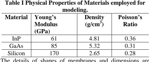
Table I Physical Properties of Materials employed for modeling.
Material Young’s Modulus (GPa)
Density (g/cm3)
Poisson’s Ratio
InP 61 4.81 0.36
GaAs 85 5.32 0.31
Silicon 170 2.65 0.28
The details of shapes of membranes and dimensions are presented in Table1. The details of physical properties of all materials used in this study are presented in Table I.
Theoretical background
The values of displacement and stress distribution have been evaluated theoretically using the following formulae [6] as per the shape of the membrane and further these values are verified corresponding to simulation results.
Maximum stress in the square membrane is given by
𝜎𝑚𝑎𝑥 = 1.25𝑃
ℎ2 𝑎
2……….. (1)
Maximum deflection for square membrane is calculated by
𝑊𝑚𝑎𝑥= −0.0138 𝑃
𝐸ℎ3 𝑎
4………..(2)
Where
α, β = Coeffients for the maximum Stress & deflection
P=Applied pressure h=Thickness of diaphrgm B=Length of diaphrgm E=Young’s Modulus
Maximum stress in the rectangular membrane is given by
𝜎 =6𝑃(𝑚 +1) 47𝑚 ℎ2 𝑎
2……….. (3)
Maximum deflection for rectangular membrane is calculated by
𝑊𝑚𝑎𝑥 =
−𝛼𝑃 𝐸ℎ2𝑏
4……… (4)
Maximum stress in the circular membrane is given by
𝜎𝑚𝑎𝑥 = 1.25𝑃
ℎ2 𝑎
2………..…. (5)
Maximum deflection circular membrane is calculated by
𝑊𝑚𝑎𝑥 =
1−𝑣2 𝑃 4.13𝐸ℎ3𝑎
4……… (6)
III. RESULTSANDDISCUSSIONS
When pressure ranging from 0.1 to 1 MPa is applied on the membrane of three different shapes for InP material, then the circular membrane found to exhibit high displacement in comparision with square, rectangular & triangle diaphragms. Simulations have been carried out for each case corresponding to constant thickness of membrane of 7 & 10 µm. From these results, it was clear that the membrane of 7 µm thickness has exhibited highest displacement than that of 10 µm for the all the cases. The maximum displacement for the applied load of 1 MPa found to be 50.8 µm of InP under 7 µm thickness. The corresponding simulations are presented in Figure 1.
(a) (b)
(c) (d)
Fig. 1 Displacement Vs applied load of a) Rectangle b) Square c) Circular shape and d) Triangle membranes using InP material.
(a) (b)
(c) (d)
Fig. 2 Displacement Vs applied load of a) Rectangle b) Square c) Circular shape and d) Triangle membranes using GaAs material
In figure 2 shows the high displacement in GaAs circular membrane comparision with
[image:2.595.46.289.438.539.2] [image:2.595.314.540.535.684.2]From these results, it was clear that the membrane of 7 µm thickness having highest displacement than that of 10 µm for the all the cases. The maximum displacement for the applied load of 1 MPa found to be 38.1 µm of GaAs under 7 µm thickness.
(a) (b)
(c) (d)
Fig. 3 Displacement Vs applied load of a) Rectangle b) Square c) Circular shape and d) Triangle membranes using silicon material
From the Figure 3, circular membrane of Silicon material exhibits maximum displacement for applied load ranging from 0.1 to 1 MPa.comparision with square, circular & triangle diaphragms simulations have been carried out for each case corresponding to constant thickness of membrane of 7 & 10 µm. From these results, it was clear that the membrane of 7 µm thickness has exhibited highest displacement than that of 10 µm for the all the cases.
(b)
[image:3.595.322.534.48.199.2](c)
Fig. 4 Pressure Vs Displacement of (a) Rectangle (b) Square Rectangle (c) Circular shape membranes using
silicon material
[image:3.595.52.286.118.279.2]In the figure 4 represents the variation of displacement with respect applied pressure for silicon materialthe Pressure (KPa) Vs Displacement (µm) with silicon material for different shapes like rectangular,sqaure and circular shapes respectively.
Table II Pressure Vs Displacement of Square, Rectangle, and Circular shape membranes using Silicon material Thicknes
s 10 µm 7µm 10µ
m 7 µm 10 µm 7 µm Pressure
(KPa) Displacement (µm)
Square Rectangle Circle
100 0.07 0.19 0.51 0.8 0.67 1.95
200 0.13 0.39 1.02 1.6 1.34 3.9
300 0.2 0.58 1.4 2.4 2 5.84
400 0.26 0.78 2.04 3.2 2.67 7.79
500 0.33 0.97 2.55 4 3.34 9.74
600 0.39 1.17 3.06 4.81 4.01 11.7
700 0.46 1.36 3.57 5.61 4.67 13.6
800 0.52 1.55 4.08 6.41 5.34 15.6
900 0.59 1.75 4.59 7.21 6.01 17.5
1000 0.67 1.94 5.1 8.01 6.68 19.5
0 0.2 0.4 0.6 0.8 1 1.2 1.4 1.6 1.8 2
10µm
7µm
D
isp
la
ce
me
n
t(
µ
m)
Pressure(KPa) Rectangle Shape
0 1 2 3 4 5 6 7 8
7µm
10µm
Pressure(KPa
)
D
isp
la
ce
me
n
t(
µ
m)
Square Shape
0 5 10 15 20 25 30
7µm
10µm
Pressure(KPa)
D
isp
la
ce
me
n
t(
µ
m)
[image:3.595.58.282.428.764.2]Table III Displacement and Stress of different Diaphragms
Materials InP GaAs Silicon
Diaphragm Thickness
10µm 7µm 10µm 7µm 10µm 7µm
Displacement
(µm) Rectangle 1.68 4.98 1.28 3.71 0.66 1.94
Square 13.3 38.9 9.98 29.2 5.1 14.9
Circular 17.3 50.8 13 38.1 6.66 19.4
Triangle 0.73 2.12 0.56 1.6 0.28 0.82
Maximum
Stress (N/m2) Rectangle 1.98E+08 4.67E+08 2.02E+08 4.94E+08 2.36E+08 5.17E+08
Square 5.33E+08 1.14E+09 5.44E+08 1.18E+09 6.18E+08 1.30E+09
Circular 4.63E+08 9.91E+08 4.92E+08 1.02E+09 5.17E+08 1.05E+09
Triangle 1.17E+08 2.97E+08 1.24E+08 3.13E+08 1.30E+08 3.20E+08
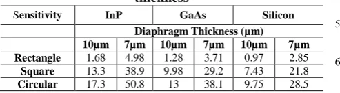
Table IV Sensitivity of different Materials at 1MPa and thickness
Sensitivity InP GaAs Silicon Diaphragm Thickness (µm) 10µm 7µm 10µm 7µm 10µm 7µm Rectangle 1.68 4.98 1.28 3.71 0.97 2.85
Square 13.3 38.9 9.98 29.2 7.43 21.8
Circular 17.3 50.8 13 38.1 9.75 28.5
The Table III shows the displacement and maximum stress for rectangular, square, circular and triangle shape membranes with the thickness 10µm and 7µm using different materials InP, GaAs and Silicon respectively. The table IV shows the Sensitivity for rectangular, square and circular shape membranes with the thickness 10µm and 7µm using different materials InP, GaAs and Silicon respectively.
IV. CONCLUSION
MEMS based pressure sensor has been designed and simulated under various diaphragms like square, rectangular and circular based pressure sensor and different output parameters like stress, deflection and sensitivity by using COMSOL Multiphysics. From the analysis of results, maximum deflection obtained from the circular diaphragm and maximum stress getting from rectangular diaphragm. simulation results allowed us to conclude that, it has been observed that the pressure sensor with circular membrane provided InP material found to exhibit more deformation and high sensitivity of 50.8×10⁻¹² for 7 µm thickness.
ACKNOWLEDGMENTS
The authors would like to acknowledge National Program on Micro and Smart Systems (NPMASS), IISc, Bangalore for establishing National MEMs Design Centre (NMDC) in our institution. NMDC facilitates to carry out these works.
REFERENCES
1. Vidhya Balaji and K.N.Bhat, “A Comparison of Burst Strength and Linearity of Pressure Sensors having thin Diaphragms of Different Shapes”, Journal of ISSS, India, 2, (2012), 18-26.
2. Suja K J, E Surya Raveendran and Rama Komaragiri, “Investigation on better Sensitive Silicon based MEMS Pressure Sensor for High Pressure Measurement”, International Journal of Computer Applications, 8(72), (2013),40-47.
3. Ashish, T.Shanmuganantham, “Design of MEMS Pressure Sensors for Environmental Applications”, IEEE, 2(3), (2014), 10-16.
4. A. Nallathambi and T.Shanmuganantham, “Design of Diaphragm based MEMS Pressure Sensor with Sensitivity Analysis for Environmental Applications”, Sensors & Transducers, 188(5), (2015), 48-54.
5. Berns A, Buder U, Obermeier E, Wolter A, Leder A and Aer Berns, “Aero MEMS Sensor array for high-resolution wall Pressure measurements”, Sensors and Actuators A, 132, (2006), 104–111. 6. Tingzhong, Xu & Lu, Dejiang & Zhao, Libo & Jiang, Zhuangde &
Wang, Hongyan & Guo, Xin & Li, Zhikang & Zhou, Xiangyang & Zhao, Yulong., “Application and Optimization of Stiffness Abruption Structures for Pressure Sensors with High Sensitivity and Anti-Overload Ability”., Sensors. 17(9) (2017), 10.3390/s17091965. 7. A.Nallathambi and T.Shanmuganantham, “Design and Analysis of
MEMS based Piezoresistive Pressure sensor for Sensitivity Enhancement”, Materials Today, Proceedings 5, (2018), 1897-1903. 8. Samitier, J. Puig-Vidal, M, Bota, S.A. Rubio, C. Siskos, S.K.
Laopoulos, “A current-mode interface circuit for a piezoresistive pressure sensor”, IEEE Transactions on Instrumentation and Measurement, 47(3) (1998), 708-710.
9. Bariian.A.A. Park, W.-T. Mallon, J.R.; Rastegar, AJ. Pruitt, B.L, “Semiconductor Piezoresistance for Microsystems”, IEEE Proceedings, 97(3), (2009), 513-552.
10. N. Ahmadzadeh, J.Karamdel, “Simulation and Analysis different MEMS Pressure sensor uses Comsol Multiphysics5.2”, Inter disciplinary Researches in Computer, Electric, Mechanic and Mechatronic Engineering, (2016), 1-14.
11. Krutideepa Bhol, “Highly Sensitive MEMS based Capacitive pressure sensor Design using COMSOL Multiphysics& its application in Lubricating system”, Science PG-Engineering Applied Science, 2(4), (2017), 66-71.
12. Hugo Chambon, Pascal Nicolay, Gudrun Bruckner and Ayech Benjeddou, “Analysis of the sensitivity to pressure and temperature of a membrane based SAW Sensor”, International Journal of smart and nano materials,8 (2-3), (2017), 95-109.
AUTHORSPROFILE
Dr. Rambabu Busi working as a Professor in the Dept. of Electronics and Instrumentation Engineering, Lakireddy Bali Reddy College of Engineering (A) since 2016. He has published 15 papers in highly repute International Journals and presented more than 10 papers in International /National.