International Journal of Innovative Technology and Exploring Engineering (IJITEE) ISSN: 2278-3075, Volume-8 Issue-10, August 2019
Abstract: Block based Discrete Cosine Transform (BDCT) is commonly used to detect and remove blocking artifacts in the compressed images. We proposed spatial domain post processing algorithm with four fold model. In the initial stage, pixel vector (PV) is calculated for horizontal as well as vertical block boundaries, after defining PV calculation of different threshold values is made for extracting blocking artifacts. These thresholds are basically adaptive to the image quality due to strong correlation with the PV. To avoid ringing artifacts across block edges directional filter is proposed. Our research further worked on region classification based upon activity of PV within the blocks. Based upon different PV activity regions separate filters are used to achieve best filtering and finally Symmetrical Pixel Normalization filter (SPN Filter) is used to normalize the values of symmetrical pixel value for better visual performance . Proposed technique various indices like PSNR, MSSIM, GBIM are calculated and compare with different post processing techniques used in literature
Keywords : BDCT, blocking artifacts, GBIM, PSNRB, SPNF.
I. INTRODUCTION
In recent scenario, high data transmission is the need of hour which requires large bandwidth. The main constraint in transmission of data is basically non-availability of bandwidth. In image and videos data transmission, compression of data is done to avoid problems that arise due to large bandwidth. Earlier compression was done by just implementing JPEG, JPEG-2000 for images and MPEG for video which itself produced lots of artifacts. Now-a-days lot of development has been done in this area.One of the technique named Block-based Discrete Cosine Transform (BDCT) which has been widely used for image and video compression is now worldwide accepted by various existing international coding standards such as JPEG for still images and MPEG [1–3] i.e video formats or simply saying moving pictures and H.261 [3] for videophone/teleconference because of its compaction property and ease of implementation..
Revised Manuscript Received on August 09, 2019.
* Correspondence Author
Anudeep Gandam*, ECE, Ph.D Research Scholar, IKG-Punjab Technical university, Jalandhar, India. Email: [email protected]
Dr. Jagroop Singh Sidhu, ECE, DAVIET, Jalandhar, India. Email: [email protected]
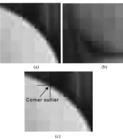
(a) (b)
(c)
Fig 1. Typical blocking artifacts of JPEG decompressed images. (a) Staircase noise. (b) Grid noise. (c) Corner outlier[16-18]
During low bit rate compression, blocking artifacts develop after implementation of BDCT in which loss of information occurs due to rounding-off of high frequency coefficients during the process of quantization across block boundaries. De-blocking algorithm plays an important role in this case which helps in minimizing the blocking artifacts which has been shown in fig 1 and also improves the visual quality of the compressed images Further more while processing of blocking artifacts, block of pixels formed during BDCT can be considered as a single unit and should be coded block wise separately. De-blocking has been classified into two types one which is most commonly used in H.264 in which de-blocking is performed while compression within the loop hence named as In-loop processing. In this process coding efficiency is enhanced by avoiding adjacent block artifact propagation. Other method is post processing, this method is most commonly preferred as it is done after the image is decompressed.
A Post-Processing Algorithm for Spatial Domain
Detection & Removal of Blocking Artifacts
[image:1.595.308.560.169.454.2]II. RELATED WORK
Over the past several years, large number of de-blocking algorithm for post-processing approach to remove blocking artifacts, have been proposed. The most common method is applying LPF over the block boundaries. For Blocking artifacts, low-pass filters can accomplish great execution by using various processes but the disadvantages of the spatial filtering methodology are smoothing or over smoothing of pictures because of its low-pass property. Various strategies have been proposed to mitigate blocking artifacts in the DCT area. Low-pass filtering smoothens out the high-frequency parts close to the limits of DCT blocks. Be that as it may, low-pass filtering brings about the accessible information on the first un-coded picture. Iterative calculations of POCS (projections onto these convex sets) recuperate the original picture from the coded one. But these techniques for the most part have high computational multifaceted nature and subsequently are hard to adjust to continuous/real time picture handling applications. Luo et al. proposed a simple DCT-based de-blocking method for smooth regions [5].In this technique, due to use of LPF high frequency signals are not considered while uneven regions are not regulated . Human eyes are more sensitive to low frequency signals than to high frequency signals. As this method was not much workable on blocking artifacts, it resulted in poor performance across the output images[6-7]. In [8] signal disintegration based strategy was proposed and its advanced technique was explained in [9]. This technique was caused by over blurring due to separation in DCT domain, particularly in comprehensive regions.[10-11]. Also, these are all more unpredictable strategies than spatial sifting. Iterative post processing methodologies were at first proposed by Youla and Webb [12,13],. Some traditional POCS calculations are exhibited in References [12] and [13]. Zhai and Zou's and strategy has highly complicated nature with better implementation [14-15]. A quick DCT space calculation removes every parameters that is required to recognize the nearness of blocking artifacts, utilizing HVS properties. Artifacts are then lessened utilizing a versatile technique. Lee et al. proposed a post-processing algorithm to decrease the blocking artifacts in JPEG packed pictures subsequent to characterizing them into edge zone and monotone area as indicated by the edge outline is gotten in the wake of thresholding the absolute gradient picture [16]. Luo and Ward [17] and Singh et al. [18] created strategies, which secured the edge info. These methods basically depend upon artifacts reduction in smooth region of the decompressed images. Smooth and non-smooth regions are basically distinguished by intensity of boundary pixels of two adjacent blocks while using DCT. But these techniques used lots of computational tasks because of several iterations while performing DCT and IDCT and hence fails in term of complexity. To avoid above mentioned artifacts/defects, we proposed a new post processing de-blocking algorithm for DCT coded image using adaptive filtering with much lesser complexity and highly efficient technique. This work develops a new computationally efficient de-blocking algorithm that effectively reduces the blocking artifacts with improved subjective and objective picture quality. In this proposed algorithm firstly sharp edge detection is performed using adaptive thresholding. Region classification is used in second step of proposed method, to remove stair case noise and
corner outlier, desirable adaptive filters have been used to the different blocks depending upon threshold values and other statistical properties of the image under consideration. During the final stage of proposed algorithm two step adaptive filter like directional filters will be implemented to reduce ringing artifacts along the edges while preserving other details and finally Symmetrical Pixel Normalization filter (SPN Filter is used due to symmetrical artifacts occur in images) to perform subjective details of the final image.
III. PROPOSED ALGORITHM
Fig 2. Pixel Vector distribution (For block size K=8) Let us consider F(x,y) images of M x N =512x512 size standard images and scanning is done with lexicographical manner with order M x N x 1 in a row. Let ƒ = [ Ɨ(0) , Ɨ(1) , Ɨ(2) ,…………. Ɨ(MN-1) ] and let Ҏ is pixel value of each pixel such that ƒ = ҎMN x 1. [Ɨ(.)] in a given image..
Let PVi is the pixel vector of 8x8 block size as shown in Fig. 2, such that p ќ =[ pќ (0), pќ (1)………pќ (K-1)]
Mathematically
PVќ(i)= Ɨ (K×ќ –{K/2} +i),
and j multiple of MN (1)
PVќ ∈ Ҏ K×1, j =1, ..., MN/K−1, K is basically no. of pixels used for one pixel vector(PV) here we are using K=8 for symmetrical artifacts to be de-blocked. BDCT is done using 8x8 blocks and as we are using symmetrical images like 512x512, 256x256, etc . therefore pixel vector is also symmetrical about the horizontal as well as vertical block boundaries. This is clearly shown in Fig2. From this point we can figure out one thing that blocking artifacts are removed horizontal as well as vertical side by side in the same manner. We can start scanning either vertically or horizontally and then rotate the scanner or image by 900 .
3.1 Proposed Algorithm:
Step1: Read an image and apply BDCT to divide image into 8x8 size blocks
Step2: We have to extract/differentiate different regions from the de-blocked images smooth region (Low activity region(LAR)), intermediate region(Medium activity region(MAR)) and Non smooth
[image:2.595.308.549.211.343.2]International Journal of Innovative Technology and Exploring Engineering (IJITEE) ISSN: 2278-3075, Volume-8 Issue-10, August 2019
Step 3: For defining different region we have to take threshold values for comparison, based upon this threshold
value we can figure out different regions so that every region can be treated in different way to reduce
artifacts.
Step4: The region classification is very helpful in designing adaptive filters which are useful in obtaining artifacts
free output in a particular region.
Step5: At the end all the region obtained after implementing adaptive filtering is combined to obtained an artifact free image.
Step 6: Proposed algorithm is tested using various indices like
PSNR, MSE, SSIM, MSSIM, GBIM. etc.
3.2Flowchart of proposed algorithm:
Fig3: Different region (LAR, MAR, HAR) classification based proposed algorithm using adaptive filters
3.3Different thresholds used in proposed work:
Whenever Block Discrete Cosine Transform is done on JPEG compressed images block based discontinuity takes place to calculate such discontinuities various threshold parameters are consider in this research paper like Ⱦќ, ȾɌ , Ⱦ₳₣. It is very important to design and select the value of threshold in such a manner that the pixel vector(PV) will find the artifacts throughout the proposed method as shown in Fig 2.
The first local value of threshold condition is written as |PVќ (K/2) - PVќ(K/2 -1)| < Ⱦќ (2) Here the threshold Ⱦќ is used to calculate and separate the artifacts from the edges of de-blocked compressed image and ќ tell about the pixel vector at ќth value. An efficient
de-blocking algorithm is one which preserve original image sharp edges while extracting edges over block boundaries but this should be done without implementing over smoothing to the block boundaries. The ringing effect so known as Gibbs phenomenon in mathematical methods of image processing is the annoying effect in images and video appeared as rippling artifact near sharp edges. This effect is caused by distortion or loss of high frequency information in an image across edge of different blocks.
No
Flat Edge Filters
Region based Filters Output image is
artifacts free
No Read an Image
After applying BDCT, Calculate pixel vector (8x8 blocksize)
Compute Threshold value Ⱦќ
If |PVќ (K/2) - PVќ(K/2 -1) | < Ⱦќ
Yes
NO Artifacts
occurs across edges
Determine region of activity (Ǽ)
Low Activity Region (LAR)
If Ǽ <μ Medium Activity Region(MAR) If μ< Ǽ < γ
High Activity Region(HAR) If Ǽ > γ
Directional Filter If |PVќ (K/2) - PVќ(K/2 -1) | < ȾɌ
If |PVќ (K/2) - PVќ(K/2 -1) | < Ⱦ₳₣ Yes
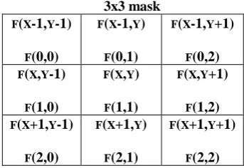
The efficient procedure to remove ringing effect in the de-blocking images is by implementing directional filter. The detail procedure of implementing directional filter is as follows:- 3x3 mask F(X-1,Y-1) F(0,0) F(X-1,Y) F(0,1) F(X-1,Y+1) F(0,2) F(X,Y-1) F(1,0) F(X,Y) F(1,1) F(X,Y+1) F(1,2) F(X+1,Y-1) F(2,0) F(X+1,Y) F(2,1) F(X+1,Y+1) F(2,2)
Fig 4. Directional Filter to remove ringing effect across edges (3x3 window size)
Fig 4. Shows 3x3 window sized directional filter which is used to remove ringing effect across edges of block boundaries. Let f(x,y) the original pixel in the image which may contain ringing effect , Let f′(x,y) be the new pixel which will be replaced with original pixel f(x,y) as follows:
f′(x,y) = (3)
where
is the weight corresponding to different pixel need to be changed using 3x3 filter mask the value of weight will be given by
(4)
The easiest method is to replace the pixel values containing artifacts with some constant values [10-11]. In any case, every irregularity at the piece limit is diverse because of the debasement impact, i.e., there exists a solid connection between's the edge and the DC quantization factor (QF).At high values of QF artifacts are more severe as compare to low QF. Therefore we should obtain and relation between threshold value and QF so that for large values of QF threshold should also be proportionally increased i.e. threshold must be adaptive w.r.t QF.
Mathematically
Ⱦќ = ά *e (ƛ*SD)* QFß (5) where
ƛ=-0.009,SD is standard deviation,ά & ß are observationally parameters having values equal to 187.5 & 0.02 respectively. Now we have three regions where the level of artifacts are different, hence we have to design different filters for these regions which means we require different threshold value corresponding to different regions as image’s local properties changes drastically therefore these threshold should neither have a fixed value not dependent only upon QF factor rather it depends upon local properties of images also. The value of threshold will be large for smooth regions of consecutive PV and small for non-smooth regions so that for smooth region it preserves all edges of blocks and only remove the artifacts in smooth regions where as in non smooth regions QF should be small enough to preserve haziness effects in the images. After formation of threshold next step is to design region classifier based upon the value of region activity (Ǽ) as shown in Fig 5.Classification based upon degree of smoothness of pixel vector in different regions are as follows:
If Ǽ <μ
Low Activity Region (LAR) If μ< Ǽ < γ
Medium Activity Region(MAR) If Ǽ > γ
High Activity Region(HAR)
As PV works in different regions(LAR,MAR & HAR), therefore PV should also be adaptive in nature so that it will works efficiently in different regions and hence activity Ǽ should also be relative w.r.t PV. Based upon different regions, ȾɌ threshold will be considered as ȾLAR , ȾMAR &ȾHAR for LAR,MAR & HAR regions respectively.
Mathematically
Ǽ = (6)
Where
(7) = 0 otherwise
&
defines relationship between adjacent pixel, it can be calculated by
(8)
Where μ & γ are constants, empirically its values are fixed as 1 & 3 respectively.
So as to diminish the blocking artifacts between two adjacent horizontal as well as vertical blocks, the pixel values over the blocks limit are altered. The quantity of pixels to be adjusted relies on the way of the locale to be sifted (smooth, non-smooth, and intermediate region). If the modifications in the artifacts effected pixel have been done without checking the nature of block boundaries it will leads to more blocking artifacts. Hence the modification in the images must carefully done after getting complete knowledge of the content of the images. Fig6. Depicts three cases of blocking artifacts due to behaviour of pixels which generally occur in smooth (Low activity region(LAR)) region.
(a) (b) (c )
Fig6: Three different types of pixel vector in LAR region(Ǽ=1)
Fig 6. Shows different activity and artifacts which are generally produced in the block based DCT images in Low activity region Type (a) is a
simple case of zero activity and flat PV without artifact, Type (b) shows one activity without
[image:4.595.82.254.115.233.2]International Journal of Innovative Technology and Exploring Engineering (IJITEE) ISSN: 2278-3075, Volume-8 Issue-10, August 2019
artifact where as Type (c) shows clear case of one activity as well as artifacts in LAR region.
Medium activity region (MAR) where the value of Ǽ lies between μ=1 & γ=3(max) are shown in Fig 7.
(a) (b) Fig 7. Artifacts in MAR region(Ǽ=2)
Fig7. Shows artifacts occurred in medium activity region when Ǽ =2. Type (a) shows occurrence of artifacts in pixel vector along with activity along block boundaries whereas type(b) shows artifacts free pixel vector in plan region.
In high activity region, the value of activity (Ǽ) > γ and graphically represented in Fig 8.
[image:5.595.312.539.51.105.2](a) (b)
Fig 8: Artifacts in HAR region(Ǽ>3)
To reduce such blocking artifacts and simplify computational complexity de-blocking filters are necessary to implement on Low activity region we have to design a new artifacts free threshold Ⱦ₳₣ , this threshold is adaptive to image information contents due to which it helps in obtaining pixel vector (PV) at block boundaries without blocking artifacts . To reduce complexity of algorithm Ⱦ₳₣ = 0.012 Ⱦќ and the associated condition to this threshold is as follows:
|PVќ (K/2) - PVќ(K/2 -1) | < Ⱦ₳₣ (9)
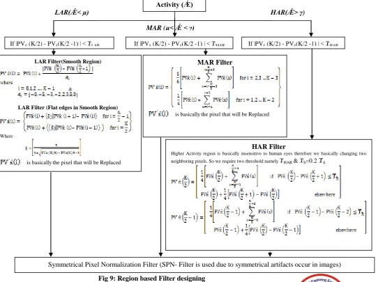
If the above said condition is satisfied, pixel vector is said to be artifact free otherwise Regions filters will be implemented. The region wise filter designing is explained in Fig 9.
Filter Designing:
[image:5.595.47.283.120.190.2]Filter classification/Designing for different regions are shown in Fig 9. Such that ȾLAR= 0.8Ⱦќ , ȾMAR=0.6Ⱦќ & ȾHAR=0.4 Ⱦќ
Fig 9: Region based Filter designing Activity (Ǽ) LAR(Ǽ< μ)
MAR (μ< Ǽ < γ)
HAR(Ǽ> γ)
If |PVќ (K/2) - PVќ(K/2 -1) | < ȾLAR If |PVќ (K/2) - PVќ(K/2 -1) | < ȾMAR If |PVќ (K/2) - PVќ(K/2 -1) | < ȾHAR
LAR Filter(Smooth Region)
& ]
LAR Filter (Flat edges in Smooth Region)
Where
§ =
is basicallythe pixel that will be Replaced
HAR Filter
Higher Activity region is basically insensitive to human eyes therefore we basically changing two neighboring pixels. So we require two threshold namely ȾHAR & Ⱦħ=0.2 Ⱦќ
MAR Filter
is basicallythe pixel that will be Replaced
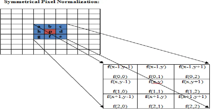
[image:5.595.21.561.357.762.2]Fig.10 Symmetrical pixel normalized filter As the blocking artifacts are symmetrical about the block
boundaries, Its very helpful to implement Symmetrical pixel normalized filter(SPNF) . SPNF works on the desired pixel by calculate the neighboring 9 pixels average vale and replace the new intensity value with the original value like in Fig 10. Red block shows a pixel value that needs to be changed with new value by calculating the average of a,b,c,d,e,f,g,h pixels and replace the pixel value of p with the new value this process will be repeated over the whole image to get better results.
IV. SIMULATION RESULTS:
Various test images(512x512) are taken to perform objective measurement & verification of the proposed method using various metrics like PSNR, SSIM, MSSIM, DBIM w.r.t different results already obtained by researchers in literature. The test images used in this research paper are as follows
(a) (b)
The performance of proposed algorithm is evaluated by comparing the results with conventional methods used in Y. Luo et al.[12], C. Wang et al.[16], Jagroop Singh et al.[18], J. Jin et al.[20] and Jin Wang et al.[21].
(a) (b) (c)
(d) (e) (f)
Fig12: Visual comparison of Lena (512x512) at 0.25 bpp (a) Ref.[12] with PSNR=31,(b) Ref. No [16] with PSNR=30.8 (c ) Ref No.[18] with PSNR=30.83,(d) Ref
No.[20] with PSNR=30.6,(e) Ref. No.[21] with PSNR=29.96 & (f) Proposed method with PSNR=31.83
(c)
[image:6.595.324.537.413.612.2]International Journal of Innovative Technology and Exploring Engineering (IJITEE) ISSN: 2278-3075, Volume-8 Issue-10, August 2019
Table I: PSNR/SSIM/GBIM vs bpp of test images Lena (512x512)
Metrics bpp Proposed Ref.[21] Ref.[ 20] Ref.[18 ] Ref.[16 ] Ref.[ 12]
PSNR
0.17 29.45 28.53 28 28 27.8 28
0.21 30.24 28.99 29.2 29.3 29.2 29.1
0.25 31.83 29.96 30.6 30.83 30.8 31
0.31 33.32 31.08 32.2 32.3 31.9 32.2
0.36 34.24 31.88 32.7 32.8 32.2 32.9
0.46 35.39 33.04 34 34 33.6 33.4
SSIM
0.17 0.79 0.78 0.76 0.77 0.76 0.77
0.21 0.85 0.84 0.81 0.81 0.82 0.82
0.25 0.93 0.98 0.86 0.87 0.87 0.86
0.31 0.97 0.97 0.89 0.87 0.88 0.89
0.36 0.99 0.98 0.92 0.93 0.92 0.92
0.46 0.99 0.99 0.94 0.93 0.94 0.92
GBIM
0.17 1.28 1.3 1.75 1.75 2.56 2.4
0.21 1.13 1.2 1.74 1.7 2.5 2
0.25 0.98 1.15 1.6 1.65 2.2 1.75
0.31 0.89 1 1.55 1.6 1.76 1.5
0.36 0.86 0.75 1.5 1.5 1.52 1.45
0.46 0.75 0.54 1.45 1.4 1.4 1.3
(a) PSNR vs bpp (Lena) (b) SSIM vs bpp (Lena)
(c ) GBIM vs bpp(Lena)
Table II: PSNR/SSIM/GBIM vs bpp of test images Barbara (512x512)
Metrics bpp Proposed Ref.[21] Ref.[ 20] Ref.[18 ] Ref.[16 ] Ref.[ 12]
PSNR
0.2 30.19 29.02 23.5 23.4 23.4 23.5
0.28 33.09 30.87 24.8 24.8 24.8 24.7
0.33 33.77 31.71 25.3 25.2 25.3 25
0.44 34.21 32.44 27 27.1 27 25.8
0.54 34.09 32.48 28.2 28.2 28.3 28.2
0.69 33.77 32.61 29.5 29.5 29.6 29.6
SSIM
0.2 0.85 0.67 0.65 0.65 0.65 0.65
0.28 0.97 0.72 0.69 0.67 0.62 0.68
0.33 0.99 0.74 0.72 0.72 0.71 0.7
0.44 0.99 0.8 0.75 0.75 0.75 0.72
0.54 0.99 0.79 0.79 0.79 0.79 0.78
0.69 0.99 0.91 0.84 0.82 0.83 0.82
GBIM
0.2 1.19 1.2 1.7 2 3.25 2.25
0.28 0.9 1.1 1.6 1.75 2.2 1.75
0.33 0.86 1 1.5 1.5 1.75 1.65
0.44 0.79 0.9 1.4 1.4 1.6 1.49
0.54 0.76 0.8 1.35 1.3 1.49 1.48
0.69 0.75 0.75 1.3 1.2 1.46 1.25
(a) PSNR vs bpp (Barbara) (b) SSIM vs bpp(Barbara)
International Journal of Innovative Technology and Exploring Engineering (IJITEE) ISSN: 2278-3075, Volume-8 Issue-10, August 2019
[image:9.595.45.501.91.707.2]Fig 14: Comparison of different de-blocking algorithm along-with proposed method using different metrics (a) PSNR (b) SSIM & (c) GBIM vs bpp of Barbara(512x512)
Table III: PSNR/SSIM/GBIM vs bpp of test images Pepper (512x512) Metrics bpp Proposed Ref.[21] Ref.[ 20] Ref.[18 ] Ref.[16 ] Ref.[ 12]
PSNR
0.18 29.42 28.43 27.8 28 27.8 28
0.22 30.21 28.92 29.8 29.7 29.7 29.8
0.25 31.74 29.69 30.3 30.3 30.2 30.2
0.31 34.04 31.75 31.4 31.5 31.4 31.3
0.37 34.84 32.45 32.3 32.5 32.5 31.8
0.47 35.34 33.54 33.3 33.3 33.2 32.3
SSIM
0.18 0.78 0.76 0.78 0.78 0.78 0.77
0.22 0.85 0.84 0.83 0.83 0.83 0.82
0.25 0.93 0.89 0.84 0.84 0.84 0.83
0.31 0.98 0.89 0.88 0.88 0.88 0.87
0.37 0.99 0.91 0.89 0.89 0.88 0.88
0.47 0.99 0.93 0.93 0.93 0.93 0.9
GBIM
0.18 1.28 1.4 1.5 2.7 2.8 2.25
0.22 1.16 1.35 1.45 2.45 2.4 1.75
0.25 1.03 1.25 1.45 2 2.2 1.65
0.31 0.86 1 1.4 1.75 1.75 1.5
0.37 0.8 0.87 1.35 1.6 1.65 1.45
0.47 0.74 0.8 1.3 1.5 1.5 1.4
(a) PSNR vs bpp (Pepper) (b) SSIM vs bpp (Pepper)
(c ) GBIM vs bpp(Pepper)
V CONCLUSION:
This paper mainly focused on blocking artifacts detection and reduction using Quality factor based adaptive thresholding in JPEG compressed images and local properties of images for edge preservation and artifact reduction . in next step pixel vector is calculated to obtain different regions of artifacts namely LAR, MAR, HAR and to calculate all these regions an activity is assumed. Based upon different activity regions different filters are designed. To reduce ringing effect directional filter is used. To further reduce blocking artifacts symmetrical mean filter is designed which produces better PSNR, SSIM, GBIM and subjective visual results. Results clearly depicts that proposed method reduces all types of blocking artifacts while preserving the information of original image.
REFERENCES
1. Wallace GK. The JPEG still-picture compression standard. Commun ACM 1991;34:30–44.
2. Mitcheel JL, Pennebaker WB, Fogg CE, Legall DJ. MPEG video compression standard. New York: Chapman & Hall; 1997.
3. ITU Recommendations H.261. Video Code for Audio Visual Service at p x 64 k bits/sec; 1993.
4. Reeve HC, Lim JS. Reduction of blocking effects in image coding. Opt Eng 1984;23:34–7.
5. D.-K. Kwon, M.-Y. Shen, C.-C.J. Kuo, An improved adaptive deblocking filter for MPEG video decoder, Proc. SPIE 5685 (Jan. 2005) 702.
6. J. Xu, S. Zheng, X. Yang, Adaptive video-blocking artifact removal in Discrete Hadamard Transform domain, Opt. Eng. 45 (8) (Aug. 2006) 080501.
7. G. Zhai, W. Zhang, X. Yang, Image deblocking based on multi-scale edge representation, Proc. SPIE 6043 (Mar. 2005) 60430F
8. Yang Y, Galatsanos NP, Katsaggelos AK. Regularized reconstruction to reduce blocking artifacts of block Discrete Cosine Transform compressed images. IEEE Trans Circ Syst Video Technol 1993;3:421–32.
9. Paek H, Kim R-C, Lee SU. A DCT-based spatially adaptive post processing technique to reduce the blocking artifacts in Transform coded images. IEEE Trans Circ Syst Video Technol 2000;10:36–41. 10.D. Youla, H. Webb, Image restoration by the method of convex
projections: part 1—theory, IEEE Trans. Med. Imaging 1 (2) (Oct. 1982) 81–94.
11.S. Liu, A.C. Bovik, Efficient DCT-domain blind measurement and reduction of blocking artifacts, IEEE Trans. Circuits Syst. Video Technol. 12 (2002) 1139–1149.
12.Y. Luo, R.K. Ward, Removing the blocking artifacts of block-based DCT compressed images, IEEE Trans. Image Process. 12 (7) (Jul. 2003) 838–842
13.Singh S, Kumar V, Verma HK. Reduction of blocking artifacts in JPEG compressed Images. Digit Signal Process 2007;17:225–43. 14.Jin Wang, Zhensen Wu, Gwanggil Jeon, Jechang Jeong, An efficient
spatial deblocking of images with DCT compression, Digital Signal Processing, Volume 42, 2015, Pages 80-88, ISSN 1051-2004, http://dx.doi.org/10.1016/j.dsp.2015.03.009.
15.J.J. Zou, H. Yan, A deblocking method for BDCT compressed images based on adaptive projections, IEEE Trans. Circuits Syst. Video Technol. 15 (3) (Mar. 2005) 430–435.
16.C. Wang, P. Xue, W. Lin, W. Zhang, S. Yu, Fast edge-preserved postprocessing for compressed image, IEEE Trans. Circuits Syst. Video Technol. 16
17.D. Youla, Generalized image restoration by the method of alternating orthogonal projections, IEEE Trans. Circuits Syst. 25 (9) (Sep. 1978) 694–702.
18.Jagroop Singh, Sukhwinder Singh, Dilbag Singh, Moin Uddin, A signal adaptive filter for blocking effect reduction of JPEG compressed images, AEU - International Journal of Electronics and Communications, Volume 65, Issue 10, 2011, Pages 827-839, ISSN 1434-8411,
19.Lee YL, Kim HC, Park HW. Blocking effect reduction of JPEG images by signal adaptive filtering. IEEE Trans Image Process 1998;7:229–34. 20.J. Jin, R. Gu, J. Yuan, A novel image deblocking method based on
curvelet trans-form, in: Proc. ICNC, 2011, pp.1800–1804.
21.Jin Wang, Zhensen Wu, Gwanggil Jeon, Jechang Jeong, An efficient spatial deblocking of images with DCT compression, Digital Signal Processing, Volume 42, 2015, Pages 80-88, ISSN 1051-2004,
AUTHORS PROFILE
Anudeep Gandam received the B.Tech. degree in Electronics & Communication Engineering from Punjab Technical University, Jalandhar in 2005 and completed her M.Tech. degree in Electronics & Communication Engineering from Punjab Technical University, Jalandhar in 2010. She is working as an Associate Professor with the Department of Electronics & Communication Engineering in Rayat Institute of Engineering & Information Technology. She is also a life-member of ISTE. She is pursuing Ph.D. from IKG-PTU Jalandhar in the area of Image / Video Processing. She guided various graduate/post graduate projects. She has also successfully guided 6 M.Tech. thesis in the area of Image/ Video processing. She has awarded best teacher awards thrice under ISTE Chapter.