Ames Laboratory ISC Technical Reports Ames Laboratory
6-1953
Magnesium-uranium alloy system
George A. TracyIowa State College P. Chiotti Iowa State College H. A. Wilhelm Iowa State College
Follow this and additional works at:http://lib.dr.iastate.edu/ameslab_iscreports Part of theCeramic Materials Commons, and theMetallurgy Commons
This Report is brought to you for free and open access by the Ames Laboratory at Iowa State University Digital Repository. It has been accepted for inclusion in Ames Laboratory ISC Technical Reports by an authorized administrator of Iowa State University Digital Repository. For more information, please [email protected].
Recommended Citation
Tracy, George A.; Chiotti, P.; and Wilhelm, H. A., "Magnesium-uranium alloy system" (1953).Ames Laboratory ISC Technical Reports. 49.
Keywords Ames Laboratory
Disciplines
Ceramic Materials | Engineering | Materials Science and Engineering | Metallurgy
UNCLASSIFIED
Physical Sciences Readin~ Ro
UNCLASSI FfED
ISC-377
Subject Category: METALLURGY AND CERAMICS
UNITED STATES ATOMIC ENERGY COMMISSION
MAGNESIUM- URANIUM ALLOY SYSTEM
By
George A. Tracy P. Cniotti
H. A. Wilhelm
June 1953
Ames Laboratory Ames, Iowa
This report was prepared as a scientific account of Govern-ment-sponsored work and is made available without review or examination by the Government. Neither the United States, nor the Commission, nor any person acting on behalf of the Commis-sion makes any warranty or representation, express or implied, with respect to the accuracy, completeness, or usefulness of the information contained in this report, or that the use of any infor-mation, apparatus, method, or process disclosed in this report may not infringe privately owned rights. The Commission assumes no liability with respect to the use of, or for damages resulting with respect to the use of any information, apparatus, method, or proc-ess disclosed in this report.
This report has been reproduced directly from the best available copy.
Issuance of this document does not constitute authority for declassification of classified material of the same or similar content and title by the same authors.
Since nonteclmical and nonessential prefatory material has been deleted, the first
18ae
of the report is !8ge 5.Printed in USA, Price 35 cents. Available from the Office of Technical Services, Department of Commerce,
MAGNESIUM=URANIUM ALLOY SYSTEM1 by
George A. Tracy~ P. Chiotti and H. A. Wilhelm L .ABSTRACT
.L""la_ ytic al.o _,._~ray;,; thermal)) and metallographic data have been :;btai:ned in tne st'.ldy of the magnesium=uranium systemll and a proposed pr~ss diagram has been constructed.
5
Almost e;omplete liquid immiscibility was found at temperat.ures 1..:p
-:n
125.5'°C~ and the compositions of the two liquids which coe:d:st<mder a pressure of about 3 atmospheres at about 11500C are appro:dl::.ately 0.16% by weight uranium in magnesiu..11 and 0.004% magnesium in uranium. T:\18 soli.!.bi.li ty of uran.ium in magnesium decreases to nearly 0.05% p.t 675"C a."lc! to about
0.0005%
at 650°C. It was found that uranium has l.i ttle or no effect on the melting point of magnesium. The magnesium dr:;as nrot affect the uranium transformation temperatures suffichntly for detection. by the methods employed.Evid~nce has been introduced to show that the previously repcrted :ix::t.emediat·e phases i!:'. the magnesium=uranium system have been caused by im.p:zrities introduced by the crucibles used or possibly by some iJt;.'AeX' source. X=ray data show that the diffusion bands formed at the 1J.ranium=magnesiwn interface when uranium was heated in contact with magnesi-um contained in a graphite crucible are composed of urani'W!l monocar~:.de and uranium dicarbide. X=ray diffraction patterns ha·ve also shown the presence of U5Si3 a:1d USi in uranium heated in contact with magnesium ccnta.ined in a ~Hagnorite1~ ::rucible which contained a pe~entage of silicon as an impurity.
MethodE and apparatus which are suitable for the preparation of a.llnys of reactive ~tals under an inert atmosphere are disCllSsed. A heating chamber which was used to prepare alloys under pressures of
3
to4
atmospheres is shown.Crucibles made of several ceramic materials were found to be re= active or poro'J.S toward uranium and magnesium. Crucibles made from high purity magnesium oxide containing 10% by weight of added magnesium fluoride were found to be nonporous and non-reactive toward rnagnesiuxn~ ,~ra~i·JJL~ mAlts~
More specifically.v certain types of alloys if formed by magnesium and urani'Wn would be of interest in pile techn<;>logy since magnesium has a low capture cross section for thermal neutrons. Knowledge of this s~tem would be useful in any proposed application of magnesium in t:M preparation of a homogeneous fuel.v in the extraction of fission products and plutonium from uranium.~~ or as an alloying constituent to improve the properties of ura.niu.m.
Empiric.al rules have been presented in the literature which attempt
to predict the nature of an alloy sys:tem from the properties of the
component metals. These rules have been applied to the magnesium~·uraniu.m systemj) and a brief resume of the conclusions which might be drawn from tmse empirical relations is presented here. The relations and a table giving the data on which these conclusions are based are given in part
A of the appendix.
According to the size factor of Hu.-ne=Rothecy (1) ~ no extensive solid
solubility is expected. Axon (2) examined 83 binary metal systems which showed limited solid solubility. These he divided into thl"ee groups based on two factors which are determined by the difference in melting
temperatures and the difference in atomic diameter of the constituent
metalso .A.cccrding to his division of these systemsj) the magnesium=uranium system could be either of two types. It could show liquid immiscibilityo or it could have a eutectic point located near· pure magnesium on the composition scale. Hildebrand and Scott (3) give an equation which ex= presses the conditions fozo liquid miscibili tyo A·ccordin.g to this equation.~~ the magnesiwn=uraniu .. m system would be expected to show liquid immisci= bility. Hildebrand and Scott point out that a large difference in electro= negativities ·~f the constituent metals would invalidate the equation9 but no specific electronegativity differenc;e value is gi~~Ten. The differeoote between the electronegativities of ma&nesium and uranium is uncertain.ll but i t is not considered large.
The high vapor pressure of magnesium at temperatures near the metlting point of uranium along with the reactivity of these metals toward atmos·~
pberic gases and crucible materials has required special techniques in the study of this systemo
The purpose of this investigation is to establish the phase diagram for the magnesil.lllll=uraniwn system. X=ray studies» thermal analyses, and the usual metallographic techniques have be~n employed to obtain the
ISC-377 7
III. REVIEW OF LITERATURE
A search of the literat.ure has shown that no complete study of the
magnesium~uranium system has been made. Results of heating uranium in
contact with magnesium have2 in a number of instances~ indicated the
possible existence of compounds in this system. None of these postulated
compounds have been prepared in a ·pure form or identified.
Ahmann (4) ~ formerly of this laboratory~ did much of the previous work on the magne.sium-uranium system. One of the several methods used
by Ahmann involved the reduction of uranium tetrafluoride in the presence
of a large excess of magnesium. In these experiments~ the magnesium
wet the surface of the uranium~ but there was no apparent reaction of the
magnesium=uranium interface. The maximwn solubility of magnesium in uranium interface. The maximum solubility of magnesium in uranium was
indicated to be 100 -ppm. In another set of experiments)) chips or pieces
of uranium were held i~ molten magnesium for a short time. There was no
good evidence of a reaction between the metals~ and after recasting the
uranium» a maximum of only 80 to 100 ppm of magnesium was found to be
present. Later refinements consisted of holding uranium powder~ or pieces
of uranium9 i.n mol ten magnesium for 24 to 48 hours in graphite o:t• gra~
phite=lined iron crucibles. A rea·ction layer was found at the magnesium=
uranium interface in several instances~ and at times~ the phase formed
at the interface extended into, the magnesium. .x~ray analysis of the layer material showed the presence o£ uranium IOOnocarbide and some .addi=
tional unidentified lines which were assumed to· pos.sibly be from an inter=
metallic compound of uranium and magnesium. These studies indicated the
maximum content of magnesium in uranium. to be 430 ppm. One sample of magnesium which had been heated at 1025°C in contact with excess uranium
was found by chemical analysis to contain 0.2.75% uranium •
.A...l'l intermediate phase was also found at· the _ma.gnesium~uranium inter~
face by investigators at Battelle Memorial Instit~te (5) when a bar of
uranium was immersed in molten magnesium at 880°C for one hour. This
intermediate phase was believed to be due to the existance of a compound in this system.
Weiner (6), in later diffusion studies at this laboratory~ found that two diffusion bands were formed at the uranium-magnesium interface when a bar of uranium was held for 6 hours at 700°C in a bath of magnesium
contained in a graphite crucible. Weiner1s uranium sample which had been cleaned in lsl nitric acid was introduced irito the molten bath at
7000C and held in suspension by means of a tungsten wire to prevent direct
contact with the graphite crucible. A helium atmosphere was used
to
ex-clude air. His results were interpreted to indicate the possible existm ce
of two compounds in this system.
is stable between 6£0 and 715°C~ and that the body~centered cubic (gamma) form is stable above 7150C. Dahl and Van Dusen (9) used electrical resistivity measurements to determine the transition temperatures. They reported that~ on heating» the temperature of the alpha to beta transition was 66t°C 3 and that of the beta to gamma was 772°0. On cooling» the
respective temperatures were 645 and 764°C.
The melting point. of Magne:si\llil is reported in the llliMetals Handbook~a
(10} as 6.50 t 2oc. Schaum and Burnett (11) used inverse rate cooling curve methods to obtain 648.1 ! 0.2°0 for the meltin§. point of magnesium. They also reported that a temperature of 648.5
'!
Oo5 C was obtained byelectrical resistivity methods. ·
The temperature of the normal boiling point of magnesium is reported as lllOOC in the WMetals Handbookit (10). Schneider and Esch (12) give 1103
t
5
°
C
for the normal boiling point of magnesiumoThe uranium» as well as all other materials and equipment JJ was made
available by the Ames Laboratory of the Atomic Energy Commission at Iowa State College. Uranium from several lots was used in this investigationJJ and an analysis of each lot was not obtai~d. Several analyses of material equivalent to that used indicate the major impurities to be
35
ppm irons 200 to 400 ppm carbon» 10 ppm manganese.~> and5
ppm magnesiumoThe magnesium used in this investigation was obtained from two sourceso The greater portion was Dow pure ingot magnesium. The manufacturergs
specifications were not available.~> but a qualitative spectrographic analysis showed the presence of a small amount of iron and lesser amounts of beryl= lium» aluminum.~> calcium» copper.!) and silicon. Chemical analysis showed
0.021$%
iron. The presence of copper could not be detected chemically. The remaining portion of the magnesium used was produced at Ames Laboratory by a double distillation of less pure metal.. A chemical analysis of this :magnesium showed the presenceot
0.00~3% iron and no de·tectable amount of copperoThe crucibles used in this investigation were made at Ames Laboratory troa AGR grade graphite» berylliaJj 11Magnorite" (a coaercial DIB.gnesia).l> and pure magnesiUil oxide to which 10% of MgnesiUJil nuoride had been added
9
V. APPARATUS AND GENERAL POOCEDURE
Due to the high vapor pressure of the magnesium and to the reactivity of both magnesium and uranium toward atomospheric gasesll a system was designed to allow samples to be heated under an inert gas at a total pres~ sure of 3 to
4
atmospheres. The increase in external pressure was apractical method of reducing the rate of distillation of the liquid mag-nesium.
A. Heating System
The details of the stainless steel (AISI 309) heating vessel used as a part of the experimental apparatus are sho'Wil in Figure 1. A photograph of the essential part of the assembly is shown in Figure 2. A mechalical vacuum pump was used to evacuate the system before flushing and filling with an inert gas which was either helium or argon. The gas was passed
through a heated (600°C) nickel tube which was packed with zirconium turnings and calcium chips in order to eliminate any reactive impurities. An arrange-ment of valves allowed the use of hydrogen when desired. A kanthal wire wound resistance furnace was used to heat the stainless steel vessel. The conduit was
l/4
inch black iron water pipe with the exception of a length of black rubber vacuum hose on both sides of the heating vessel. This hose allowed the vessel and its contents to be easily remov~d from the furnace and quenched in water. This procedure was used to rapidly cool molten samples in order to prevent possible segregation of constituents with a high densit,y such as uranium which might precipitate and settle out on normal cooling. The heating vessel was used for diffusion studies» for a portion of the liq-uidus studies» and for thermal analyses.B. Diffusion Studies
The purpose of these studies was to obtain evidence for the possible existence of one-plu?-se regions in the magnesium-uranium system. If inter-metallic compounds are formed itt a system» their presence will be indicated by the diffusion bands or layers formed when the two components of a binary system are heated in contact with each other for a sufficiently long period
ot
time. These bands will correspond» in the order of their occurrencej to the single-phase regions of the phase diagram at the temperature and pressure at which the diffusion bands are fonned (13).In the procedure used in these experimentsj a uranium bar in contact with magnesiumi contained in a graphite» beryllia, or ttMagnorite" crucible» was placed in the heating vessel, and the heating system was evacuated to
a pressure of 10 to 1.5~. The system was then flushed and filled with
purified helium or argon to a pressure of about 2 atmospheres, and the metals were heated to the desired temperature.
A. B.
c.
D.E.
F.
G.
H.
I.
"·
K.Fig. 1
•
•
I
I
•
•
I
RUBBER 0- RING WATER COOLING COIL
TO VACUUM PUMP OR GAS OUTLET STAINLESS STEEL
c
J - - - 0
t _ _ - - - '
KANTHAL WIRE WOUND RESISTANCE FURNACE REFRACTORY CRUCIBLE
REFRACTORY BLOCK THERMOCOUPLE REFRACTORY BLOCK
THERMOCOUPLE ~OTECTION TUBING GAS INLET
Construction Details and Arrangerrent of Heating Chamber.
[image:10.547.167.439.54.452.2]ISC-377
-·
~=-
-...
...
Fig. 2 Pressure Apparatus and Heating Chamber
[image:11.549.55.503.62.485.2]and if conditions were favorable9 this material could react ~th the
uranium and deposit a layer of the reaction product on the surface of the uraniumo A.ny such layer caused by an unsuspected third component
could easily be misinterpreted as an additional single=phase region of
the systemo The layer could also restrict the diffusion process to
such an extent that 1 t would prevent the formation of bands which normally should form and thus lead to a misinterpretation of the phase relation=
shipso In order to reduce these possible effects of impurities to a
minimum9 the crucibles used were of the various compositions mentioned
above o It was believed that the effect of a possible impurity from one
type of crucible would not be duplicated on a similar sample prepared in
a different type crucible" Diffusion studies were also made on uranium crucibles that had been used in several experimentso
Co Determination of the Liquidus
If a sample containing a liquid and a solid in contact with each other is heated for a sufficiently long period of time 9 the liqUid will
dissolve the u-.aximwn or equilibrium amount of the solid for that temper=
ature o If the sample is quenched rapidly enough to retain all of the
dissolved mater.ial9 chemical analysis of the portion which was liquid can be used to determine the amo1.mt dissolved at the temperatwreo The
purpose o£ these studies was to det.ennine the line 9 know as the liquidus 9 which joins these equilibrium liquid phase compositions at the different
temperatureso The procedures used for this det.erminatioxrinvolved the
heatJ.ng of massive uranium and uranium shavings or powder in contact w1 th
magnesium contained in refactory crucibl-es and the heating of magnesimn
in uranium containerB o
In a number of related experiments 9 massive uranium or urB.Il-i um
shavings were heated in contact with magnesium in crucibles mad,e from atMagnorite1al) graphite.~~ berylliti\" pu:;:'e magnesi'W'!!. o:xide9 or pure •.. a.gnesiwn
oxide to which 10% magnesium fluoride had been addedo The all~~,-s were
prepared in the heating vessel by the use of the sQI)le procedure employed
for the diffusion experiments o In accordance -with the above general
procedure9 a sample cf what had been the liquid phase was removed from.
the quenched alloy and a ~hemical analysis was obtainedo In a variation of this method» several magnesium samples were taken f:rom a large amour.1t
of magnesium as i t was heated to progressively higher temperatures in
contact with solid u::raniumo In this case:. the liquid magnesium was con~ tained in a large crucible made from the magnesium oxide=magnesium fluoride :mixture and was heated in a monel tube under argo1n at a pressure slightly
13
by dipping a small graphite crucible into the melt and then quenching t.he crucible and its contents in an oil bath. Another method used to obtain data for the determination of the liquidus involved the heating of pressed billets of -uranium shavings in contact with magnesium in magnesium oxide= magnesium fluoride crucibles which were sealed in iron bombs under argon. Part of the purpose of the two latt..er methods was to determine the time needed to reach equilibrium. In one case» an attempt was made to determine the time by taking samples at different intervals at the same temperature. In the other» several bombs were placed in the muffle furnace at the same time and removed after different time intervals at temperature.
In order to increase the area of contact between the uranium and the magnesium and thus attain equilibrium conditions in a shorter time» uranium powder was used in a series of experiments. These experiments were con= ducted in the heating vessel by placing uranium turnings on top of a cylinder of magnesium in a refractory crucible. Then the uranium turnings were con= verted to uranium powder through the hydride process according to the method reported by Chiotti and Rogers (14). In this method» a stream of hydrogen at. about one atmosphere pressure is passed over the uranium turnings at a temperature of 225 to 250°C to give the hydride which is then decomposed by continued heating to above 450°C. The hydrogen liberated by the decomposition of the uranium hydride was flushed out of the system by a flow of helium at a pressure slightly greater than one atmosphere. Just before the melting point of magnesium was reached~ the outlet valve on the heating chamber was closed and the remainder of the heating cycle was d:me under approximately three atmospheres of helium pressure. After holding for a desired period of time at temperature~ the sample was quenched in the manner previously described.
Finally~ in the attempt to eliminate any impurities introduced by the
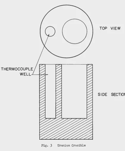
crucibles~ magnesium was heated in uranium crucibles such as shown in Figure
3. The experiments employing these uranium crucibles in the heating vessel were carried out in the same manner as in the other experiments except that an internal thermocouple was used. In a later modification9 a capped uran~ ium crucible~ called a bomb» was used to prevent contamination of the melt by possible impurities remaining in the gas. The uranium bomb is shown in Figure
4.
The samples for chemical analysis were obtained by taking dril= lings from the quenched magnesium-rich phase.D. Thermal Analyses
The apparatus used for most of the thermal analyses consisted of a
heating vessel very similar to the one used for the preparation of the alloys~
THERMOCOUPLE
WELL.-L---f-?~
Fig. 3 Uranium Crucible
TOP VIEW
[image:14.545.57.478.80.586.2]15
The
purpose of these studies was to determine if uranium lowered the melting point of the magnesium.~> and to determine the effect of magnesiumon the solid transformations in uranium by the measurenent of the temper=
atur~s at which the thermal arrests took place on heating and cooling. Standard differential methods were employed. In most cases a nickel referen~e body was used. In determining the effect of uranium on the melting point of magnesium a pure magnesium reference body was used.
Chro.mel~alumel thermocouples were u..<:1ed with the cold junctions in an ice bath.
E. Preparation of Alloys for Microscopic Examination
The standard methods of grinding and polishing were used in the pre= paration of the alloys for microscopic examination3 but the etching pro~ cedures were varied.
Several chemical etching solutions were tested in the preparation of uranium samples for examination3 but none were completely satisfactory.
Cathodic etching was used almost exclusively for pure uranium and was also used with favorable results on uranium-rich alloys. Two chemical
etching solut,.ions which gave satisfactory results for some uranium~rich alloys were a solution of 10% hydrofluoric acid in methanol and a solution
composed of 2 parts of a saturated water solution of sodium fluosilicate and potassium tartrate and 1 part eoncentrated nitric acid. This latter solution will be referred to as 11etchant A11 •
Pure magnesium was easily etched by several reagents~ but a very good polish etch was obtained with a solution of 11etchant A11 diluted ls2 to ls4 with distilled water. An etchant which was almost as good was a solution of
8%
nitric acid in ethanol. These solutions also prod~ced good etches on magnesium=rich alloys.Many of the alloys produced in this investigation contained large areas of both a magnesium~~ich phase and a uranium-rich phase. These two phases exhibited a large difference in hardness and in reactivity toward etching solutions. The wet polishing of these samples resulted in the abrading away of the magnesium to such an extent that there was a large difference between the level of the two surfaces by the time the scratches from the sanding operations were removed from the uranium. Also» no
etching solution was found which would satisfactorily etch both the uranium and the magnesium phases simultaneously. The only solution to the problem was the polishing and etching of the sample for the examination of the magnesium-rich areas and then polishing and etching for the uranium=rich areas. This resulted in very poor definition of the interface region.
F. X-Ray Analyses
Both a Debye~Scherrer type camera and a "Norelco" x-ray diffractometer
Debye-THREADED
CAP
SIDE
SECTION
ISC-371
17
Scherrer cameras the x-~ray diffraction pattern was recorded on a photo= graphic emulsion. Massi~.re samples were used when the 11Norelco11
dif-fractometer was employed9 and the diffraction pattern was recorded on
the chart of the associated recorder. The normal techniques were used in the measurement of these patterns and in the identification of the phases present.
VL EXPERIMENTAL RESULTS
The proposed phase diagram of the magnesium-uranium system as
construct,ed from thermals analytical» and microstructure data is shown
in Figures
5
and 6.Since the results of the experiments in this investig~tion were
dependent» to a large degree~ upon the method of procedure used» some details of the procedures will be given at the same time that the results are presented.
A.. Diffusion Studies
The results of the diffusion studies were very dependent on the
crucible material used. A.s shown in Figure
7
» two diffusion balds wereobserved in a sample heated for 6 hours at 700°C in a graphite crucible
under a helium atmoshphere o The rectangular bar of uranium used to
prepare this sample was first cleaned in lgl nitric acid to remove the
oxide film. In an attempt to prevent the formation of a new film of oxide9 the cleaned sample was immersed directly into the molten magnesium
at 700°C as s~on as possible after cleaning. In order to prevent direct
contact between the uranium and the graphite~ the uranium was held sus= pended in the magnesium by means of a tungsten wire o The obse:rved bands
that formed at the interface in this experiment were interpreted to indicate the presence of two intermediate single-phase regions in the
phase diagram of tm magnesium-uranium system.
In
another experiment in which uranium was heated at about l075°C in contact with magnesium in a ''Magnoriten cruciBle.~~ the magnesium filtered through the crucible walls and was in contact with the wallaof the stainless steel heating chamber. The uranium of this sample had mel ted» and examination of th~ alloy showed that two liquid phases had been formed. The structures observed in the uranium-rich phase are
shown in Figures 8 and 9 o These microstructures show what might be
interpreted as a eutectic structure and a peritectic reaction. However3
(.)
0
..
MAGNESIUM- URANIUM
SYSTEM
~LIQUID I LIQUID 2~
1
140 0 ~ I
I I
1 I
1 I
1 LIQUID I ;- LIQUID 2 I
I I
1200 !..
I
I
1133°
I
1000 1- LIQUID
+
y URANIUM800
-
769°LIQUID
+
{l
URANIU~6100
-
/ 650°./...
...,
LIQUID+
a
URANIUM ......,
200
-MAGNESIUM
+
URANIUMI
II
I
0 20 40 60 80 100
WEIGHT PERCENT
URANIUM
[image:18.544.72.463.176.563.2]ISC-377
19
MAGNESIUM-RICH END OF MAGNESIUM-URANIUM SYSTEM
1200
1000
u
0 800
..
w
a::
::::>
~
a::
LLJ Q.~
LLJ
...
0
LIQUID I (LIQUID I / o
+LIQUID
2K
/ 1133°
/
/
0
0
LIQUID
+
Y URANIUMLIQUID
+
~ URANIUM661°
MAGNESIUM -t a URANIUM
0.04 0.08 0.12 0.16
WEIGHT PERCENT URANIUM
0.20
Fig. 6 Liquidus at Magnesium-Rich End of Magnesium-Uranium Phase
[image:19.548.47.515.56.646.2]•
Fig. 7 Diffusion .Bands in
Uranium Heated in Contact with Magnesium in Graphite Crucible
for
6
Hours at 700°C, Na2SiF6-K2C4H406-HN03 Etch, X 250 (Uranium at ]ottom.)
Fig. 8 Uranium Contaminated
by Nickel from Stainless Steel Heating Chamber, Heated in Con-tact with Magnesium at 1075°C in "Magnoritett Crucible, 10% HF
in Methanol Etch, X
50.
••
Fig. 9 Reaction Ring
Around Crystallite in Uranium Contdminated with Nickel, Cathodic Etch, X
1000. (Same alloy as shown
[image:20.544.31.511.54.657.2]ISC=377 21
Several other experiments were made with the use of 11Magnorite11
crucibles which9 in these instances9 were placed inside a larger crucible
of either graphite or beryllia. In each case3 samples heated above the
melting point of uranium showed that two liquid phases had been formed.
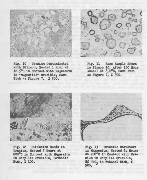
Figure 10 is a photomicrograph showing the structure observed in the uranium=rich phase of a sample which had been heated at 1215°0 for
one hour in a nMagnorite" crucible. This photomicrograph also shows what
might be interpreted as a eutectic structure. Figure 11 shows the same
sample after annealing at 850°0 for 100 hours. This microstructure in=
dicated the possibility of t~ compounds in the magnesium=uranium system. It was later founds howeverj that the "Magnorite" crucible contained a
certain amount of silicon.
Other e~periments involved the use of beryllia crucibles to contain
the melt. Figure 12 shows the diffusion bands in uranium after the
uranium was heated in contact with lnagnesium for
5
hours at 800°C in aberyllia crucible. This structure was very puzzling. Figure 13 shows
the eutectic-like structure for:ned at the grain boundaries of the magne-sium-rich phase of a sample which had been heated in contact with uranium in a beryllia crucible for
24
hours at 900°C. A spectrographic analysisshowed an approximate tenfold enrichment of beryllium in the magnesium
of this sample over the beryllium content of the magnesium used as the
starting material. The use of beryllia was then discontinued» and neither structure shown in Figures 12 or 13 was found again ..
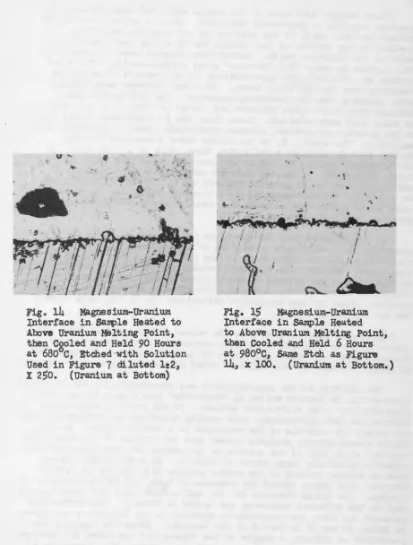
After the above studies~ an examination was made of a section of uranium crucible in which magnesium had been heated for a total of
24
hours at temperatures between650
and1015°C.
This crucible did not show any evidence of diffusion bands. Similar examinations were made on sections of uranium bombs in which magnesium had been heated for even longer ~riodsin the same temperature range» and agains no diffusion bands were found. Figures
1.4
and 15 show the absence of diffusion bands in two different samples. Figure14
is a photomicrograph of the magnesium-uranium interface region of a sample in which uranium had been heated in contact with magne-sium to a maximum temperature of 1230°C in a magnesium oxide~magnesium fluoride crucible» and then cooled to 6S0°C. The sample was held at thistemperature for 90 hours and then quenched. Figure
15
shows a part ofthe interface area of a sample which had been heated to a maximum of 1205°C and then cooled to 980°C. After 6 hours at this temperaturell the sample was quenched. Both samples were polished for only a· short time and etched very slightly in order to maintain the same surface level for both the uranium-rich and the magnesium-rich phases.
Fig. 10 Uranium Contaminated with Silicon, Heated 1 Hour at 121S°C in Contact with Magnesium in "Magnori te11 Crucible, sa~ Etch as Figure 7, X SOO.
Fig. 12 Diffusion Bands in Uranium, Heated S Hours at 800°C in Contact with Magnesium in Beryllia Crucible, Cathodic Etch, X 100.
.:
.
Q~Q~.:
;) ..
·
~
·
·
<
~
.
•
ta=-...
~
.· ..
~~
~
"J~··
..
v0
·
l?
j ?~/ 4; It' , ' • * ~ . • ) (
. . '# (} - • • . ·~
~_) ::. ~·
•"'
-(.
,_(:)
., ... Fig. 11in Figure Anneti.l at as Figure
Same Sample Shown 10, After 100 Hour 8S0°C, Saroo Etch
7, X
Soo.
Fig. 13 Eutectic Structure ir1 Magnesium, Heated 24 Hours at 900°C in Contact with Ura-nium in Beryllia crucible, 8% HNOJ in Ethanol Etcll, X
[image:22.542.27.503.66.648.2]ISC-377 23
u •. (j
..
.
-
.
Fig. 14 Magnesium-Uranium Interface in Sample Heated to Above Uranium Melting Point, then Cooled and Held 90 Hours at 680°C, Etched-with Solution Used in Figure 7 diluted 1:2, X 2$0. (Uranium at Bottom)
• I
&,.. • i .,
\< -· • ..;. ' \ •
~~,
....
~,..;.,..0 ~
I
/
I
I
,
~
-
'
~
J.
a
Fig. 15 Magnesium-Uranium Interface in Sample Heated to Above Uranium Melting Point, then Cooled and Held 6 Hours at 980°C, Same Etch as Figure
[image:23.544.43.504.60.668.2]this surface by means of a onNorele;o0~ x=ray diffractometer. The first
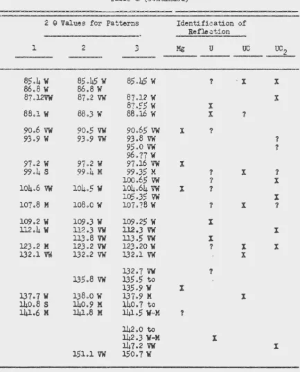
pattern was obtained with approximately 0.6 millimeters of magnesium remaining over the diffusion bands. Two ot...'ller patterns were obtained after grinding away the remaining magnesium. The diffraction lines obtained from these three patterns are listed in Table 1 in the order
in which they were obtained. These lines can be attributed fairly well to the presence of uranium.!) uranium monocarbide" uranium dicarbide" and magnesium. The symbol)) X3 in the column under a compound or metal
denotes that it produces a reflection whose value of 2 Q is equal)) or is very nearly equalo to that of the observed reflection shown at the left. The symbol~ ? !) denotes that the metal or compound produces a
reflection near to the observed reflection» but its identification may be doubtfuL Tables containing the literature values for the character= istic x~ray diffraction patterns for these metals and compounds are
given in part B of the appendix.
It may be noted that the agreement between the values of the obser= ved reflections which were identified as uranium dicarbide and the liter= ature values for the reflections of the compound are not too good in
some cases. However~ the agreement between the values for the reflections calculated from the lattice constants given in the liter a ture and the li.terature values for the observed reflections i.s also not good" The observed values for the identified reflections lie in the ran~ between the two literatu~e values.
It should also be noted that the values of 2 G and sin2 Q for all tables of x~ray diffraction patterns correspond to the use of copper K=alpha radiation. Also)) the system of notations given in footnote otaii
of Table 1 is used in all tables of x~ray patterns given in this report.
The identity of the impurity~which was responsible for the st~1cture
ISC=37?
25
Table 1
X=Ray Diffraction Patterns of Magnesium=Uranimn
Diffusion Co~ple Heated in Graphite
2 9 Vall::.es for Patterns Identification of
Reflection
l 2 3 Mg
u
uc
uc
231.7
}fl31&5
M 31~32 M X32.2 M
32.2
M32.29
w
X.34.6
M34.5
M34.43
s
X36.0
w
35.94
M X36.3
w
36.26
M X36.35
w
X36.8
s
36.75
s
36.67
s
X46.6
vw
46.5
w
X47o5
w
47.6
w
47.85
w
X52.4
w
52.3
w
52.23
w
X ?52.8
M52.9
w
52.85
vw
X60.9
vw
60.9
vw
60.9
vw
?62.3
w
62.3
w
62.21
w
X ?.62.9
M63.05
M63.12
M X63.32
w
?64.6
w
?65.2
w
65.2.w
65.22
vw
? X68.67
w
68.9
w
68.90
s
68.89
w
X70.2
M 10.2w
?0.20
vw
X72 .. 58
w
X75.5
vw
75.5
vw
75.4
vw
I76.2
vw
76.2
vw
76.15
w
X?6.9
vw
?6.9
vw
76.8
vw
X X83.65
vw
? 1&
Refle c:ti.on
1 2
u
8,5o4 W 85.4.5
w
85.45
w
?-
X
86.8
w
86.8w
87 .l2VW 81.:2
vw
87.12w
87.55
w
I88.1
w
88 • .3w
88.16w
I 190.6
vw
90.5vw
90.65vw
I 193.9
w
93.9
vw
93.8vw
95.0vw
96.11
w
97.2
w
91.2
w
9?.16vw
X99.4
s
99.4
M 99.35 M ? X100.65
vw
?104.6
vw
104.5
w
104.64vw
I ?105 • .35
vw
107.8 M 108.0
w
107.?8w
? I109.2
w
109 • .3w
109.25w
Xll2 .4
w
112.3
vw
112.3vw
113.8
vw
ll.3.5vw
X12.3 .2 M 12.3 .2
vw
123.20w
? X1.32-.l
vw
1.32 .2vw
132.1vw
X1.32.7
vw
?135.8
vw
135.5
to1.35o9 W i
l.37.7W 1,38.0
w
1.37.9 M X140.8
s
140.9 M 140.7 to141.6 M
141.8
M
1.41.5
W=M 1142.0 to
142.3
W-M X1.47.2
vw
151.1
vw
1$0.7w
X
X
?
?
1
I
X
?
X
X
[image:26.542.47.481.81.618.2]ISC-377 27
Table 2
X=Ray Diffraction Pattern of Uranium Heated
in Contact with Mg in 11Magnorite"
Intensity Sl.n " 2 G Identification of Diffraction Line
Uranium u5si3 USi
wa
0.0601 Xw
o.c64.3
? ?vw
0.07h7 ?vw
o
.
otr
t
'
X XM 0.0900 X
M-S 0.0944 X
s
0.0971 Xvw
0.1107 ? ? 1w
0.1260 XM 0.131.3
S (broad) 0.1531 ?
vw
0.1760w
0.1950 ? ?vw
0.2o60 Ivw
0.2271 ? 1vw
0.2370 IM-S 0.2562 X
M 0.2613 I
vw
0.2709 ? X Xvw
0.2775vw
0.2857 Xvw
0.3161 Xw
0.3247 X ?M 0.3484 X ?.
M-8 0.3578 X
M 0.3868 I
vw
0.4253 Xvw
0.4470 Ivw
0.5350
I Ivw
0.5849 ? Ia Where a line was definitely identified as uranium» no attempt has been
[image:27.541.54.484.106.642.2]Uranium.
u
5
s1
3 USivw
0.6081 ? Ivw
0.6248 Xvw
0.6318 Xvw
0.6481 Ivw
0.6781 ? I 1vw
0.7444 Iw
o.
1619 Xw
0.1153 Ivw
0.1982 Xvw
0.8029 Xvw
0.83.51 Ivw
0.8493 Ivw
o.~?Q Ivw
0
.
8?66
Xvw
0.8119 IM Oo9876
In view of these x-ray data and the fact that no diffusion bands or
componnds were formed when magnesium was heated enclosed in a uranium
bomb 3 it is concluded that no compounds exist in the magnesium~uranium
system.
B. Determination of Liquidus
After it was determined t~t no intermetallic compounds existed
in the magnesiUJ~Furanium system» the determination of the ]jquidus
[image:28.540.52.484.80.386.2]remained as the major problem. The resultant liquidus curve9 shown in
Figure 6 ~ was obtained by a combination of data obtained by several
methods.
1. Determination of the solubility of uranium in liquid magnesium
Before the complete results. of the diffusion studies were available,
attempts were made to prepare alloys in ttMagnorite"~ graphite, or beryllia
crucibles. Most of these attempts were made with the use of the uraniua
powder metb:>d. In samples prepared by this method.~~ the powder bad been
partially ,sin tend into spongy disks which usually sank to 'the bette. o'
the crucible. The upper portion of the magnesium was removed, and the
[image:28.540.49.472.92.386.2]ISC-317 29
analyses are shown in Table 3. These results were not considered in the construction of the liquidus line shown in Figure 6 since these crucible
materials were shown to introduce appreciable amounts of impurities into
the magpesium melt.
a.. Ex:periments in Hhich magnesium oxide-magnesiu.rr fluoride crucibles were used. Crucioles made in this laboratory from very finely divided high purity magnesium oxide were porous toward liquid magnesium. This
condition required the use of an adcli tional crucible to contain the rnagpe=
sium oxide crucible in order to prevent the liquid magnesium from coming
in contact with the stainless steel wall of the heating chamber. It was found that the addition of 10% of magnesium fluoride to the pure magnesium
oxide produced a non=porous crucible. These crucibles were completely satisfactory and. were used throughout the remainder of the investigation except for those experiments in which uranium was used as the crucible material.
Table 3
Uranium Content of Magnesium After Heating in
Contact with Uranium Powder
Temp. Time at Crucible
%
oc TemtJ. Hours Material Uranium
705a lo2 Magno rite 0.041
780 2.5 Magno rite 0.727
920
3.5
graphit..e 0.0441000 2.3 Magnorite 1.157
lo65 1.0 beryllia 1.05
1110 2.0 beryllia 0.233
1110 2.8 beryllia 1.596
a All temperatures plus or minus 10°C
A number of experiments which employed the pressure heating chamber were carried out to obtain data for the determination of the magnesium=
rich portion of the liquidus with the use of the magnesium oxide-magnesium
fluoride crucibles. Helium at a pressure of from 3 to 4 atmospheres was
maintained over the charge in each case. In these experiments~ a charge
of approximately 60 grams of either massive uranium or uranium shavings
and approximately 30 grams of magnesium was used. The charge was heated
to a temperature above the melting point of uranium for
0.5
to 1.0 hourand then cooled to the desired temperature and held for a period of time
[image:29.540.42.491.98.576.2]quenched. The method of chemical analysis used to obtain each r~su1t
is ind.ioated in the table.
Examination of these samples showed that two liquid layers: had been formed in all expe::"ime~ts in which :.he sample had been heateQ. t'> above the melting point of uranium. The use of uranium shavings did n~ a.ltei" the fL"laJ. results. In each case the urani'.llll had melted and sett.~ed t :; the b.c•ttom o.f t.b..e charge. Due to the relatively large area expc.3ed by t.he s.hav:L"lgs to t.he molten m.agn.esi.um» it might. be aas1.L'1lled that near equilibrium ~onditiQns had been attained L~ the melt.
Because of the -;raria tion noted in t.he resul t.s of the .;:;hemieal analyses,~~
1u was believed that there was a faint possibility t.l-J.at. small particles of uranium» urani~ monocarbide~ or uranium dioxide had been mech&~ically
entrapped in the magnesium» althou~~ no definite evidence of entrapped partiC'.les was seen in micros co pi~ examinations of the samples. An attempt was made to differentiate between any entrapped particles and the urani.u.m in met.allic solu.t.ion by dissolution of the samples in ei.ther dilute nitric. or hydrochloric acid. However» if the particles did existJ the met.hod used did not show their presence.
In another experiment» about. 500 grams of magnesium were heated in a magne:sL.!Jn oxide=magnesi:um fluoride crucible in argon at about atmospheric presst.U"e. Approximately 100 grams of uraniwn shavings which had been cleaned in lsl nitric acid were added to the molten magnesium at 670°0.
A.
50
gram massive bar of uraniu.m» cleaned in nitric acid» was also added. After the melt had been held at temperature for a period cf time~ a5
gram ~ample of magnesium for chemical analysis was removed by irrdners~ng a small gxaphite crucible int~o the melt. The removed sample was quen0hed by immediate immersion of the graphite crucible into an oil bath. Any loose particles of graphite were removed from each crucible before it was dip~ d. m.tothe magnesium. In order to aid in t:b..e determination of the time nece6sary fcr•equilibrium conditions to be attained~ the melt was held for an additional period of time at the same temperature.\) and additional samples were taken at intervals. The temperature was then increased and the pro~cedure wae repeated for successively higher temperatures up to a maximum of llloc·c. Samples were taken in an analogous manner on cooling. The results of chemical analysis of these samples are given in Table
5.
l l l of the results in this table were obt~ined with the use of the spectro= photometric method of analysis.ISC-377 31 Table
4
Urani~~ Content of Magnesium Heated in Contact with Excess Uranium in Magnesium Oxide-Magnesium
Fluoride Crucibles
Temp. Time at Temp.
%
Uraniumoc Hours .t'olarographic
Spectrophoto-Analyses metric Analyses
655&
1.65
0.014680
4B
0.108680
48
0.020155
28 0.046785
l l 0.098785
11 o.o55900 5.8 0.088
900
5.8
0.095
990
4.5
0.136990 4.5 0.1.3.5
1080
2.3
0.1731080 2.,3 0.110
1090? 1.0
o.oa
1110°
2.5
0.10112.5
1.5
0.074112.5 1.5 0.144
11.35 1.0
0.051
ll45b 1.0 ('.2.3
ll95b
1.1 0.1111215~ 1.0 0.22
1225
4.0
0.1310°1255b
2.0 0.240·a All temperatures plus or minus 10°0 •.
b These samples were heated only to the temperature given and then quenched
c
Difficulties in rapidly quenching this sample might have allowed some
[image:31.541.39.481.68.630.2]to be reached was the primary purpose of the experiments in wr.ich uranium was heated in contact with magnesium in magnesium oxi.de~magnes:l.um fluoride crucibles which were sealed in iron bombs. .A.ddi tional points for the determination of the li.qu.id·J.s were also obtained. In these experiments
approximately
:5
grams of magnesium» contained in an oxide=flu0ride crucible» was first heated to 9000C in an atmosphere of helium. About 10 grams of cleaned uranium shavings~ which had been pressed into a briquette3 werethen dropped ir..to the molten magnesium. After 20 :rr.inutes at tr..e same ten= perature 9 the crucible was cooled u.."1.der heliu.'ll, and any oxide fiL'll on top
of the magnesium was removed by scraping. The crucible was then capped with a di.sk of the oxide·~f'luoride rna terJ..a.l. and transferred to the bomb. Argon wa:s used to f1115h the bomb before welding on the cap. Several of the bombs>~
which were made of extra heavy walled iron tubing» were placed in a muffle furnace and heated to a predetermined temperature. The bombs were removed after different time intervals and were immediately quenched in water. This procedure was repeated at several tempe:;ca tures.
The top portion of the magnesium was removed from these samples &~d
sent for c.henrl.cal analysis. 'lhe results of these analyses» show in Table
6 ~ indicate that the length of th8 heat.ing peri od was not the factor responsible for the variation of the analytical results. A spectrophoto=
metric methcd was used to obtain the results shown in this table.
b. Experiments i.n which uranium containers w~e used" Uranium ;cru= cibles were also used in the determination of the liquidus for the magne= si~~~rich portion of the system. In these experiments» the uranium crucibles were cleaned in lgl nitric acid» and a cylinder of approximately
15
gzoaJ'I!S of' magnesium which had been machined to a close tolerance was then forced into the crucible. A. thermocouple was placed i.n a thermocouple we~l pro= vided in the uranium crucible which was placed inside a graphite crucible used to prevent contact between the uranium and the walls of the heating chamber. The CI"J.Cible was t.hen heated for a pe~iod o£ time at a temperature between the melting points of magnesium and uranium. The heating chamber and its contained sample were then air cooled or quenched in water. The crucible was then removed» and a portion of the magnesium was drilled out for chemical analysis. Particular care was taken to avoid including any uranium from the crucible in the magnesium shavings obtained in this manner~because only a few milligrams of added uranium would cause an appreciable error in the results. Another cylinder of magnesium was then machined to fit into the drilled hole~ and the procedure was repeated at a different temperature. The results of analyses of these samples are shown in Table
ISC-377 .3.3
Table
5
UraniURLContent of Magnesium Removed at Intervals from a
Large Melt of Magnesium Heated in
Contact with Uranium
Temp.a Time at Temp.
%
oc Hours Uranium
65 b 0.0001
65~
0.001665
3e5 0.00.3noc
2eJ 0.056775° 1.3 0.038
775c ~-7 0.029
780C 1'.9 0.042
830 4.2 0.041
840 2.1 0.048
925° laO 0.048
930° 0.7 0.059
9.30 2.0 0.039
930 ).0 0.058
1030c 1.3 0.084
1030 3.4 0.056
1030 4.3 0.109
1040 1.1 0.143
1100 1.1
o.o6o
1110 2.6 0.252
81 All temperatures plus or minus 10°C.
b These samples were taken from the magnesium after it had been allowed
to furnace cool to room temperature in the crucible. They should represent the solubility of uranium in magnesium at the freezing point of magnesium since any uranium that precipitated after freezing wuld be retained in the sample.
[image:33.537.39.471.158.541.2]heating may have reacted to form a film of oxide or nitride$ or boths at the magnesium=uranium interface. Ther~fore, in crder ·t,o exclude all external impurities as much as possible~ the magnesium was enclosed in small uranium bombso These bombs were~ in effect» uranium crucibles with threaded caps.
The threaded cap could be screwed solidly against a uranium shoulder or against the top of a machined cylind~r of magnesium which had b~en forced
into the bomb in the same manner as was used for the uranium crucibles. After heating» a sample of magnesium was removed for chemical analysis as previously described. The results of these analyses are included in Table
1·
c. Statistical treatment of data. It can be noted that the values
reported for the concentrations of uranium in magnesium vary considerably.
Since it would be difficult to plot a liquidus line with the use of the individual values9 all values shown in Tables
4
»
5
96 and7
were combined inan attempt to obtain a reasonable mean value for the ma~esium liquidus
at the various temperatures.
In t.he met..l}od usedJ> the arithmetical mean was calculated for all tem=
peratures and for all analytical results in a small temperature range. Additional calculations were then made in this manner for successive incre= menta of temperature. An. effort was made to keep the temperature range small and yet include enough values so that an average value would be meaningfuL Where possible~ a phase transition was taken as the dividing line between successive increments of temperature. The two values obtained for the furnace cooled samples were treated separately. Each resultant
average value for the uranium content of the samples included in a temper= ature range was plotted against the average temperature of that range.
The error in the mean value fer both the temperature and the uranium content.
of a particular increment was taken as plu.s or minus the average deviat:i.on of the individual values fran the mean. The values for the temperature and the error in temperature were taken to the nearest
50C.
These mean values which were used to plot the liquidus line shown in Figure 6 are shown in Table8.
The reason for the variation of the individual values for the concen= tration of uranium in·magnesi\un is not. known. However~ a rather large variation in the values of determinations in the concentration range in~
valved is not uncommon~ and the close agre~ntbetween the mean values
or
the successive increments of temperature is evidence in itself that some type of random error is largely responsible for the variation of theISC-377
Table 6
Uranium Content of Magnesium after Heating in Contact
with Pressed Urani'W!l Shavings
Temp. Time at Temp.
%
c
c
Hours Uraniwn85o'a 16 0.107
850 34 0.034
975 18 0.055
975 40 0.052
1075 6 0.031
1075 29 0.0.30
a All temperatures plus or min1.:s 10°C.
Table
7
Uranium Content of Magnesium After Heating in
Temp.
oc
690a 100 125 765 825 850 875 930 980Uranium Containers
Time at Temp. Hours
2.4
46.
2.3 2 • .3 1.7
27.
1-.5
2.01.5
Cooling Rate
air cooled quenched air cooled air cooled quenched
quenched quenched quenched quenched
a All temperatures plus or minus lOOC.
[image:35.542.48.485.93.693.2] [image:35.542.52.485.378.659.2]Liquidus for Magnesimn.=Rich Port.ion c.f Magnesium-Uranium System
No. of Temp. Range Ave. Temp. Ave.
%
Values oc
oc
Uranilm2 650
0.0005
2 10 660
±
5
o.ooB'±
o
.
oo6
5
45695
±
15
0.055 t
0.0288 30
115
t 10 o.o61±
0.0241
5
0
8
45
t
lO 0.069±
0.0241 30 920
t
10 0.074'!
0.0265
15
980t
5
0.101t
0.0364
10 1030±
5
0.098 t 0.0288
35
1090
'!
15
0.112 to
.
o65
5
20 11.3.5±
5
0.124±
o.o;:1
4
60 1225 i. 20 0.190 ! 0.040contamination Jf the analytical specimens w.i.th even minute amounts of
uranium dioxide or other particles containing uranium during the prepar~ ation of the samples for analysis. Both methods of chemical analysi.s
are believed to be good~ but the spectrophotom9tric method is possibly more sem.:si ti ve than the polarographic met.hod.
2. Determination of the solubili t.y of magnesium in uranium.
An attempt was also made to determine the solubility of magnesium
in uranium. Uranium samples which had been heated in ccntact with magne=
sium to above the melting point of uranium and either quenched directly from this temperat~re or cooled and held at some lower temperature for a
period of time and then quenched were analysed for magnesium. The mag=
nesium contents of these samples are given in Table 9. The temperature indicated is thilt temperature at which the sample was heated after the original melting. The magnesium content of those samples heated below t.he melting point of uranium is probably not the equilibrium content at
the temperature indicated since the nranium was in solid state and equilibriwn could only be obtained by diffusion of magnesium through
Table 9
Magnesium Content of Uranium Heated in
Temp"
cc
655a 680 755 785 900 990 1080 1125 1135 1195 1250 1255Contact with Magnesium
Time at Temp. Hours 165. 48. 28. ll.
.s.s
4.5
2.3 1.5 1.0 1.10.7
2.0a All temperatures plus or minus 10°Co
Magnesium Content ppm 155 30 20 95 210
3'>
llO 1515
40
25
40
31to be obtained under these conditions. Although these results do not give the absolute solubility of magnesium in uranium, they indicate the probable magnitude of the solubility. The magnesium content of those samples in
which the uranium was liquid is probably very near the equilibrium value since the diffusion process is much more rapid in the liquid state o
Figure 16 shows the struct.ure of the uranium used as a starting mat=
erial for the preparation of samples in this investigation. Figure 17 :W
a photomicrograph of a uranium control sample which was relted in a mag= nesium oxide=magnesium fluoride crucible in the absence of magnesium and then que'lchedo Figure 18 is a photomi.crograph of a ·uranium samgle which had been heated in contact with mangnesium to a maximum of 1230 C » then held at 680°C for 90 hours and quenched. .The uranium used to prepare this sample was cut from the uranium control sample shown in Figure 17 o The large crystal of an impurity seen in Figure 18 is apparently produced by the agglomeration and growth of the smaller impurity crystals seen in Figure 17. Crystals of this type in uranium have been observed in the absence of magnesium and according to Mott and Haines (7))) such crystals are possibly due to uranium oxide.
[image:37.548.58.495.70.382.2]Fig. 16 Uranium Used to Prepare Samples, Cathodic Etch, X 120.
Fig. 17 Uranium Control,
Heated Above Melting Point in MgO-MgF? Crucib1.e and Quenched,
Cathodi~ Etch X 250.
Fig. 18 Uranium Heated in
Contact with Magnes:i. um in
Mg0-MgF2 Crucible to above Uranium Melting Point, then Cooled and
Held at 680°C for
90
Hours and [image:38.542.23.501.78.646.2]ISC-317
39
at temperatures up to 1250°C, and the microstructure of uranium does not show any change which could be attributed to tre addition of magnesium.
C • Thermal Analyses
The melting point of the magnesium used in this investigationj as determined by the differential cooling curve method with the use of nickel as the reference body~ was 647 ± 2°C.
A
thermal arrest at 650t
2°C was obtained during the first heating of magnesium in a uranium crucible. The thermocouple was insulated from the uranium sidewall of the thermo~couple well by a thin walled alundum tube (see Figure 3). Any thermal gradient between the thermocouple and the magnesium inside the uranium
crucible would be small since uranium is a relatively good heat conductor. When a sample of .magnesium in a uranium crucible was cooled after the
initial heating period and then reheated, the thermal arrest for the freezing point of magnesium was difficult to determine in a uranium cru= cible on cooling because the temperature of the beta to alpha transform-ation was lowered to an extent that a differentitransform-ation between the thermal arrests representing the two transitions was very difficult. Therefore, no reliable cooling curve measurements could be made. The results which were obtained indicate that uranium has little, if any, effect on the melting point of magnesium.
Differential cooling curve methods were also used in the attempt to determine the effect of uranilun on melting point of magnesium. In these experiments» pure magnesium was used as a reference body» because the temperature difference between the sample and the standard can be deter= mined with greater accuracy than can the absolute temperature of the sample. However» ~11 tne magnesiilm samples which contained uranium produced a
thermal arrest within the range found for pure magnesium» ·and no signif-icant difference between the sample and the pure magnesium could be deter= mined.
The transformations in pure .uranium were determined with the use of the uranium crucible. The weight of the crucible was 738 grams, and since the thermOcouple was in the thermocouple well inside the wall of the crucible» the thermal arrests were very pronounced. The temperatures of the thermal arrests were measured with the use of a Rubicon portable precision potentiometer. In the first experiment, a temperature of 666
±
lOC was observed for the alpha to beta transformation with a heating rate of5°C
per minute. A heating rate of 10 to 15°C per minute gave a val~a of667
i
l°C. The value of the beta to alpha transformation was determined as 656±
1°C for a cooling rate of 10 to 15°C per minute. For heating and cooling rate of 10 to 15°C per minute, the temperature of the beta~gammarates of heating.
An
attempt was made to determine the effect» i f any~ of magnesium on the transform tions of uraniumo Different-ial heati~g a.nd co .ling curves were made on a sample of uranium that had been heated i:1. contactwith magnesium for one-half hour at 1~80°C and then for
6
hours at 900°C.It was assu.rned that the liquid uranium became saturated with magnesium
i::-~ the first treatment. With heating rate of
5°C
per minute for twodeterminations» the alpha to beta transformation in the uranium was found
to occur at a temperature of 666 t 2°C l> and beta to gamma transformaticnjl
at 771
±
2c'C. On cooling9 the corresponding transforma tion.s took p~ceat
655
'!
2 and 756 t 2oc. All of these temperatures are within the tra'.'ls=formation ranges de7-ermined for pure uraniui'll. In view of the very li:mit'l!d sol':.1.bility of magnesium in uraniumjl as shown by spectrographic analyses» no pronounced change in the transformation t~mperatures for uranium was