International Journal of Innovative Technology and Exploring Engineering (IJITEE) ISSN: 2278-3075, Volume-8 Issue-9, July 2019
Abstract— The conventional method of wired charging system isn’t portable. The units must be connected to power plugs in order to function or to charge. Moving the units require time, energy, space and staff which makes the process quite difficult as well as expensive. The system arrangement can limit the options for users and the equipment placement. Wires can be damaged in case of faults, electrical surges or storms whereas the wireless units can be unplugged in any abnormal conditions. The core of this project is to design a system for a wireless power transfer; the wireless power transfer was acknowledged by Nikola Tesla. Wireless power transfer brings a remarkable change in the field of the electrical engineering which knockout the issue of conventional copper cable and current holding wires. It can be used for charging the battery of electric vehicle, charging the battery of mobile, in medical equipment, running the DC fans and other DC loads. In this project we transfer the power wirelessly and run a 12V DC fan and a CFL bulb.
Index Terms— WPT (Wireless Power Transfer), MOSFET (Metal-oxide-semiconductor field-effect transistor), FKP Capacitor (F = film/foil, K = Plastic film capacitors, P = Propylene)
I. INTRODUCTION
The standard wire system makes a mess with regards tocharging a couple of gadgets in the meantime. It also takes up a piece of electric connections and not to determine the truth that every gadget has got ready for the charging port. [1] At this point an exploration may rise. What if a solitary framework can be used to charge these gadgets in the mean time without the use of wires? We gave it a thought and came up with an idea. The course of action to all these issues lies with inductive coupling, a fundamental and convincing method for trading power wirelessly. Wireless Power Transmission is the capability transmission of electric power from primary circuit to secondary circuit without wires. This can be used for applications where either a provoke total or a constant transport of essentialness is required, anyway where standard wires are exorbitant, badly organized, expensive, hazardous, unwanted or undesirable. The transmission of power can be through Inductive coupling for short range, for mid-expand Resonant Induction is used and for high range Electromagnetic wave control trade.
Revised Manuscript Received on July 06, 2019.
Ghulam Akbar, Department of Electrical Engineering SUKKUR IBA University, Sindh Pakistan.
Syed Sabir Hussain Shah, Department of Electrical Engineering SUKKUR IBA UNIVERSITY, Sindh Pakistan.
Hafsa Shaikh, Department of Electrical Engineering SUKKUR IBA University, Sindh Pakistan
Salman Murtaza, Department of Electrical Engineering SUKKUR IBA University, Sindh Pakistan.
Alamdar Shah, Department of Electrical Engineering SUKKUR IBA University, Sindh Pakistan.
WPT is a development that can transport ability to areas, which are by and large improbable or difficult to reach. Charging low power devices and over the long mid power devices by strategies for inductive coupling could be the accompanying enormous thing. The objective of this system is to design and build up a method to transmit wireless electrical power through space and charge a desired low power gadget. Two coils will be used to transfer the electric power from an AC source to the load. Examination of various geometrical and physical casing factors surveyed with a particular true objective to extend coupling among transmitter and circuitry. An achievementin doing all things considered would take out the use of connections in the charging methodology accordingly making it less complex and less demanding to charge a low power device. It would ensure the less complexity of the device since it would wipe out the danger of short circuit. The objective moreover joins the likelihood of charging distinctive low power devices at the same time using a single source which would use a single electrical plug [2].
Parallel topology used is very beneficial in a sense that, it omits the use of reactive devices for the purpose of parallel operations and the amount of power between two is also controlled in an easy manner. And when the amount of power is increased the only method that is cost effective parallel topology because design is not changed even if the amount of power is increased in this case, and secondly the decapitation of heat is also easily controlled because of distribution of heat in the circuit. And also the devices used for this are of small ratings [3]. Multiple input and output coils can also be connected together to increase the amount and efficiency of power to be transmitted wirelessly [4].For the short range of the power transfer it is very important that the efficiency is high. The applications of wireless devices with high efficiencies uses special met materials [6].The robustness of the wireless power transfer is increased by using multiple coils [7].The electrical power that is transferred wirelessly is not affected by any object or human in between the sending and receiving end coils. There might be some effects if these objects are very near to the coils [8].Different techniques can be used for the propagation of electrical power wirelessly for different small level application to make it easy for the supply of electrical power. [9].
II. WIRELESS POWER TRANSFER METHODS
1.Inductive Coupling
Inductive coupling or magnetic coupling works on the principle of electromagnetism. When a wire is put in the surrounding of magnetic
field, another field on that wire is generated too. [3]
Ghulam Akbar, S.S.H. Bukhari, H. Sheikh, S. Murtaza, A. Shah
Transfer of energy between two coils via magnetic field is known as inductive coupling. If an amount of the magnetic flux established by one system interlinks with the second circuit, at that point two circuits are coupled inductively and the energy might be exchanged from one circuit to the another circuit. In electrical designing, two conduits are referred to as common magnetically coupled when they are arranged with the goal that change in current through one wire will cause an induced voltage in the other wire through electromagnetic acceptance. The measure of inductive coupling between two conductors is estimated by their shared inductance. [4] The output in terms of efficiency can be increased by
1. By increasing the turns of the coils 2. By increasing the magnitude of the current 3. By increasing the strength of the magnetic field 4. By increasing the cross sectional area of the coil
2.Resonant Inductive Coupling
It is also known as magnetic phase synchronous coupling. It is the type in which secondary side of the coil is loosely coupled and the coupling is increased by resonating the coil. The basic system for resonant inductive coupling includes a primary coil and a resonant inductive circuit on the secondary coil. The resonant inductance and capacitance of the secondary side are together called as a resonant circuit. When the rate of change of magnetic field of the primary is at the resonant frequency of secondary sides, the phases of the primary and secondary magnetic fields are interlocked. This is done to achieve the maximum output voltage by obtaining maximum common flux [5]. In this case the Cu losses at the primary coil are decreased, heat losses are reduced and the efficiency of the system is relatively improved.
It is near the field transmission of wireless power. The system is tuned on the resonant frequency such as driving frequency equals the resonant frequency.
3.Mathematical Modelling of Proposed Wireless PowerTransfer Scheme
[image:2.595.313.538.110.312.2]Consider Figure 1, for understanding of inductive coupling,
Fig. 1. Theoretical model of Inductive Coupling System
Where,
ZT = Impedance of the source of the transmitter circuit,
CT = Total LC tank capacitance in the transmitter circuit,
LT = Total LC tank impedance in the transmitter circuit,
RT = Resistance of the source of transmitter circuit,
IT= Total current flowing in the transmitter circuit,
CR = Total LC tank capacitance in the receiver circuit,
LR= Total LC tank impedance in the receiver circuit,
RR = Total receiver circuit resistance,
ZR= Receiver circuit load impedance,
IR=Total current flowing in the receiver circuit,
CRS = Equivalent series capacitance of CR in the receiver
circuit,
CTS = Equivalent series capacitance of CT in the
transmitter circuit,
LRS = Equivalent series inductance of LR in the receiver
circuit,
LTS = Equivalent series inductance of LT in the
transmitter circuit,
From the circuit in Fig. 1 given above, we can write,
T
Ts Ts
T C
L C
L
X
X X
X
(1)
R
Rs Rs
C
L C
R X
X X
X
(2)
T
Ts Ts
T CL
C L
C
X
X X
X
(3)
T
Ts Ts
T CL
C L
C
X
X X
X
(4)
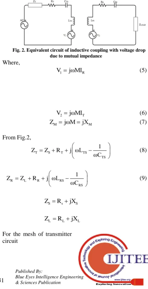
[image:2.595.301.546.364.839.2]And the equivalent circuit of inductive coupling with voltage losses is shown in figure 2.
Fig. 2. Equivalent circuit of inductive coupling with voltage drop due to mutual impedance
Where,
1 R
V jωMI (5)
2 T
V jωMI (6)
M M
Z jωMjX (7)
From Fig.2,
T S T TS
TS 1
Z Z R j ωL
ωC
(8)
R L R RS
RS 1
Z Z R j ωL
ωC
(9)
S s S
Z R jX
L L L
Z R jX
International Journal of Innovative Technology and Exploring Engineering (IJITEE) ISSN: 2278-3075, Volume-8 Issue-9, July 2019
S 1 T T
V V Z I 0 (9)
S 1
T T
V V I
Z
(10)
S M R
T
T
V Z I I
Z
(11)
For the mesh of receiver circuit
2 R R
V Z I 0 (12)
2 M T
R
R R
V Z I I
Z Z
(13)
M S M R
T
R T
Z (V Z I ) I
Z Z
(14)
2
T R M R M S
(Z Z Z )I Z V (15)
M S
R 2
T R M
Z V I
Z Z Z
M S
T
T R 2
R T R M
Z V Z
I I
Z Z Z Z
(16)
Power delivered from the primary circuit
*
*1 e S T S e T
P R V I V R I (17)
* *
R S
1 S e * * 2
T R M
Z V
P V R
Z Z Z
(18)
Received power by the receiver circuit is
* *
2 T R e L T R L
P I I R Z I I R (19)
2
*
M M S L
2
2 * * *
T R M T R M
Z Z V R P
Z Z Z Z Z Z
(20)
III. HARDWARE EXPERIMENT
The design which we have proposed consists of six major parts.
1. Rectifier
2. Oscillator
3. Transmitting coil
4. Receiving coil
5. Filtration
6. Load
1.Rectification
It is the process of converting AC – DC. It turns the direction of the AC to a constant output. Rectifiers are mainly used in power supplies, adapters and as radio signal
detectors. They are made of different kinds of diodes for example solid state diodes, vacuum diodes and mercury arc diodes with other components such as resistors and capacitors.
The AC input of 220V 50 Hz from the utility power supply is required to be converted in to high current DC. This is done using 12V 4A. The process of rectification is done in order to get a constant signal which is then later switched into high frequency using Oscillators.
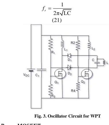
2.Oscillator Circuit
The oscillator circuit which we have used is shown in figure 3. The values of the components are given in table 1The 12 V 4A supply from adapter is given to Radio frequency chokes L1 and L2. At first current flows from L1 and L2 and through drain terminal of the n-channel MOSFETS Q1 and Q2 here IRFZ44N. By this, a small voltage will appear at gate terminals. At a time, one transistor will be in on state while the other will be in off state. The transistor which is in off state drain voltage will become greater and it will drop on the tank circuit which is made of transmitting coil L of 1uH and Capacitor C of 55nF.
This combination of L and C is done to achieve resonance frequency fr.
1
2π LC r
f
[image:3.595.48.262.55.562.2](21)
Fig. 3. Oscillator Circuit for WPT
3.Power MOSFET
[image:3.595.314.504.360.578.2]TABLEI
SPECIFICATIONS ADOPTED FOR THE SIMULATED INVERTER
Component’s Name Component’s Value
Voltage Source, Vdc 12V
Capacitor, C1 100nF, 63V
Resistor, R1, R2 100 Ω, 1W
Resistor, R3, R4 10k Ω, ¼ W
Diode, D1, D2 1N4148
MOSFET,Q1, Q2 IRFZ44N
Radio Frequency
Choke,L1, L2 100uH
Capacitor 55nF, 1000V FKP
Inductor 1uH
4.Zener Diode [IN4148]
It is a switching diode having PIV rating of 100V and maximum repetitive peak forward current is 480 mA. It provides the same functionality as a switch. It has very high resistance similar to open switch when the voltage is applied below the specified level. When the voltage is increased to a specified level, it suddenly acts as a close switch. Switching diodes have very short reverse recovery time ranges between few nano-seconds. 1N4148 switching time is 4ns.Here these diodes are used to clamp the higher voltages for Q1 and Q2. 5V are provided to the MOSFETs by this cross coupled feedback of clamping diodes
5.FKP Capacitors
This type of capacitors are used for high frequency applications such astiming circuits, LC-filters, oscillators and audio equipment circuits. Its special features are, it has a very small amount of dissipation factor, and it has a negative temperature co-efficient for capacitance and a little dielectric absorption.
6.Radio Frequency Choke
It chokes the radio frequencies. Radio frequencies are from 3 kHz to 300GHz. It blocks AC current of radio frequencies. Here two 100uH chokes are used. When power is supplied to the oscillator, current flows though these chokes.
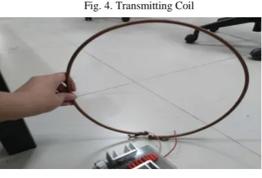
7.Transmitting and Receiving Coil
[image:4.595.331.521.51.180.2]Here the transmitting coil and receiving coil is designed using 6mm copper pipe. The copper pipe is wound in a single turn. The reason to use copper pipe is, it has greater current density and constant magnetic field when operated under high frequencies. The coil’s diameter is 1feet with an inductance of 1uH. Figure 4 and 5 shows the coils.
Fig. 4. Transmitting Coil
Fig. 5. Receiving Coil
8.Filters
The output at receiving coil is not pure DC. It has a presence of considerable amount of AC component. The load is sensitive and requires pure DC. To filter out these ripples, a capacitor of 2200uF/ 25V is connected in parallel with the load. The high frequency AC component in form of noise is bypassed through this capacitor.
9.Loads
[image:4.595.316.550.431.596.2]The current at the load terminals ranges between 0.8-1.5A and voltage from 7-16V. At first, we connected two loads in parallel, a DC fan of 12V 1.2A and a bulb of 12V 1A. The results under next section are taken with a single load of DC fan. The bulb works on DC and AC as well so, it is connected before filtration capacitor.14Watt DC fan is used as a load, which consume 12V and 1.1A at a distance of 2 inches to run at full speed.12Watt DC Bulb is used as a load, which consume 12V and 1A at a distance of 2 inches.The complete hardware for WPT is shown in figure 6.
Fig. 6. Transmitting Coil
IV. RESULTS
International Journal of Innovative Technology and Exploring Engineering (IJITEE) ISSN: 2278-3075, Volume-8 Issue-9, July 2019
TABLE 2
POWER CALCULATION AT SENDING END
Distance
(meter) Current (A) Voltage (V)
Power (W)
0.1524 2.5 12 30
0127 2.5 12 30
0.1016 2.5 12 30
0.0762 2.5 12 30
0.0508 2.5 12 30
As it is clear from the results in table 3 that with the increase in distance the amount of power is reduced. The efficiency of the model is also calculated in table 4, in which powers from receiving and sending coils are compared to find out the efficiency. The expression for the efficiency is
TABLE 3
POWER CALCULATION AT RECEIVING END
Distance
(meter) Current (A) Voltage (V)
Power (W)
0.1524 0.372 7.5 2.79
0127 0.55 9.5 4.275
0.1016 0.75 11.5 5.824
0.0762 1.1 13 13.4
0.0508 1.2 16 15.6
TABLE 4
EFFICIENCY CALCULATIONS AT NO. OF DISTANCES
Distance (meter)
Sending end power(W)
Receiving end power(W)
Efficiency (%)
0.1524 30 2.79 9.3
0127 30 4.275 14.25
0.1016 30 5.824 19.41
0.0762 30 13.4 44.6
0.0508 30 15.6 52
V. CONCLUSIONS
The goal of this project was to design and implement a wireless power transfer system via resonant inductive coupling. The fabrication of the PCB for the receiving and transmitting circuit is carried out in FAB-Lab at Sukkur IBA University, which is the only fabrication lab in Pakistan. Based on the theory of wireless charging via inductive coupling, which was the method used in the project, it was seen that various aspects determine the efficiency of Wireless Power Transfer i.e. Resonant frequency, Distance, Quality factor, Coil turns ratio. In addition, there is an exponential decay for power versus the distance of separation. After 6cm separation the power transferred began to significantly drop. WPT can be used for other applications too. In this project we have energized a 12W bulb and used a dc fan load by a two way switch.
ACKNOWLEDGEMENT
We are very thankful to Sukkur IBA University for providing us with sources and environment for research.
REFERENCES
1. Aditya, Kunwar, and Sheldon S. Williamson. (2014) “Design Considerations for Loosely Coupled Inductive Power Transfer (IPT) System for Electric Vehicle Battery Charging – A Comprehensive Review.” IEEE Transportation Electrification Conference and Expo (ITEC), doi:10.1109/itec.2014.6861764.
2. Aldhaher, Samer,“Tuning Class E Inverters Applied in Inductive Links Using Saturable Reactors.”IEEE Transactions on Power Electronics, vol. 29, no. 6, 2014, pp. 2969–2978., doi:10.1109/tpel.2013.2272764
3. Das, Suprabhat. “Review Paper on Wireless Power Transmission for Charging Mobile Devices.”International Journal of Engineering and
Computer Science, 2017.
4. Hao, Hao, “A Parallel Topology for Inductive Power Transfer Power Supplies.”IEEE Transactions on Power Electronics, vol. 29, no. 3, 2014. vol. 134, pp. A635–A646, Dec. 1965.
5. Casanova, J.j,“A Loosely Coupled Planar Wireless Power System for Multiple Receivers.”IEEE Transactions on Industrial Electronics,
vol. 56, no. 8, pp. 3060–3068, 2009.
6. Ajit Rajagopalan, Anil Kumar RamRakhyani, David Schurig. “
Improving Power Transfer Efficiency of a Short-Range Telemetry System Using Compact Metamaterials .”IEEE Transactions on Microwave Theory and Techniques, vol. 62 no.4, 2014.
7. Chen, Wei, et al. “Optimization Spatial Multiple Coil Transmitter Structure for Wireless Power Transfer.” IEEE Antennas and Propagation Society International Symposium (APSURSI), 2013. 8. Kurs, A. Karalis, R. Moffatt, J. D. Joannopoulos, P. Fisher, M.
Soijacic, “Wireless Power Transfer via Strongly Coupled Magnetic Resonances”, Massachusetts Institute of Technology, Science, Vol. 317. No. 5834, pp. 83— 86, 2007.
9. Jawad, Aqeel, et al. “Single-Tube and Multi-Turn Coil Near-Field Wireless Power Transfer for Low-Power Home Appliances.”Energies, vol. 11, no. 8, p. 1969. 2018 , doi:10.3390/en11081969.
10. A. K. RamRakhyani and G. Lazzi, “On the design of efficient multi-coiltelemetry system for biomedical implants,” IEEE Trans. Biomed. Circuits Syst., vol. 7, no. 1, pp. 11–23, Feb. 2013.
11. A. K. RamRakhyani, S. Mirabbasi and M. Chiao, "Design andOptimization of Resonance-Based efficient wireless power deliverySystems for biomedical implants," IEEE Transactions on biomedical Circuits and systems, pp. 48-63, February 2011. 12. Chen, J.-F, Ding, Z.Hu, Z.;Wang, S, Cheng, Y., Liu, M.Wei, B.Wang,
S. “Metamaterial-based high-efficiency wireless power transfer system at 13.56 mhz for low power applications.” Prog. Electromagnet. Res, 72,pp. 17–30, 2017.
AUTHORS PROFILE
Ghulam Akbarhas got his B.E in Electrical Engineering from MUET Jamshoro, Sindh Pakistan in 2013. And Masters in Electrical Engineering from QUEST, Nawabshah Pakistan in 2018. He is currently in the faculty of Electrical (Power) Engineering at Sukkur IBA University, Sindh Pakistan. The area of interest includes Power System Stability, Power System Quality, Power System Protection & Control.
Syed Sabir Hussain Shah BukhairHe received his Bachelor of Engineering degree in Electrical Engineering (Power) from Mehran University of Engineering and Technology Jamshoro, Sindh, Pakistan, in 2009, and his Ph.D. in Electronic Systems Engineering from Hanyang University, South Korea. He is currently serving as an Assistant Professor in the department of Electrical Engineering at SukkurInstitute of Business Administration. His main research interests include Electrical Machines Design, Power Quality, and Power Electronics.
Hafsa Shaikhhas got her B.E in Electrical Engineering from Sukkur IBA University, Sindh Pakistan in 2018. And is currently enrolled in Masters in Electrical Engineering from MUET Jamshoro, Sindh Pakistan. The area of interest includes, Power System Quality, Power System Protection & Control.
Salman Murtazahas got his B.E in Electrical Engineering from Sukkur IBA University, Sindh Pakistan in 2018.The area of interest includes Power System Quality, Power Electronics.
Alamdar Shahhas got his B.E in Electrical Engineering from Sukkur IBA University, Sindh Pakistan in 2018. The area of interest includes, Power System Quality