International Journal of Innovative Technology and Exploring Engineering (IJITEE) ISSN: 2278-3075, Volume-9 Issue-2, December 2019
Abstract: Fading channels learning about polar codes is great prominence. Knowledge of polar codes is very important while they are applied to the wireless communication systems. In fading Channels the communication through channel estimation which is an essential step for communication. The structure is constructed by a set of information bits for both systematic polar code and non-systematic polar code and the information set recognized frozen bits. In fading channels uneven pilot selection scheme and even pilot selection scheme are two pilot selection schemes are considered for polar codes. There is an improvement in decoding performance of polar codes using these selection schemes. In this choosing of coded symbols treated as pilots is a replacement of insertion of pilots. Polar codes have poor performance in fixed domain. So the EPS selection scheme can be active for tracing or channel estimation. The structure of polar code encoding is acapable structure and pilot selection is grave since whole selections cannot use the existing structure again. By conjoining the above advantages, pilot signals are selected without any addition from outside and insertion of pilot symbols impartial to estimation of the channel. Leveraging this, the DM-BS scheme is applyto multiple input multiple output (MIMO) system in frequency selective fading channel.
I. INTRODUCTION
Basically all channel coding technology works in same way. There are some errors occur in communication links due to random noise device impairments, interference etc. The original data stream is correct at receiving side. So two sets of operations are employs on original data stream in channel coding. Polar codes being used in 5G wireless standard due to provide great error correcting performance with low decoding complexity .When combined with more advanced decoding algorithms .This makes outstanding performance. Frequency Division Multiplexing (FDM)technique is built in this OFDM. Different information streams are plotted in FDM onto discrete frequency channels which are in parallel. Every FDM channel is divided from the others to reduce the interference contiguous channels.
With the increased future smart transportation systems, rapid mobility takes place with variable Doppler shifts with time based phenomena in wireless communication. Peak data rate problems are encountered. So we need efficient encoding and decoding schemes to increase the peak data rate in high velocity environment.Hence,5G is the better candidate to attain data rates up to 20 Gb/s for eM-BB. So, efficient coding scheme is a challenging task in wireless 5G for high mobility scenario. This project aims to observe that Polar codes are used for capacity improvements. Several researchers are
Revised Manuscript Received on December 05, 2019.
* Correspondence Author
B Pujitha, Department of Electronics and Communication Engineering, P V P Siddhartha Institute of Technology, Vijayawada, India.
K Aruna Kumari, Department of Electronics and Communication Engineering, P V P Siddhartha Institute of Technology, Vijayawada, India.
working on this continuously since long back. The current 5Generation and 3GPP trade off, polar codes are used in uplink and down link as a channel coding in eMBB type of services. Polar codes also used in Ultra low latency and massive machine type communications. Compared to advanced-codes such as Lowdensity-paritycheck (LD-PC) and successivecancellation-list (S-CL), therefore the error identification response with finite length systematic polar codes are far better.
II. BCAK GROUND OF POLAR CODES
R.Mori,et al [2]: The creators of this paper has given a short clarification about the exhibition of polar codes. These are the principal group of codes-known to accomplish limit of symmetricchannels utilizing a low intricacy progressive crossing out decoder. Despite the fact that these codes, joined with progressive wiping out, are ideal in this regard, their limited length execution isn't record breaking.
I.Tal,et al [3]: The creators of this paper has given a short clarification about the strategy for proficiently developing polar codes is displayed and broke down. Albeit polar codes are unequivocally characterized, straight forward development is immovable since the subsequent polar piece channels have a yield letter set that develops exponentially with the code length. In this manner, the center issue that should be explained is that of dependably approximating a bit-channel with an obstinately enormous letters in order by another channel having a reasonable letter set size. They devise two estimate techniques which "sandwich" the first piece channel between a corrupted and an overhauled form thereof. The two approximations can be proficiently figured and end up being amazingly close practically speaking. P.Trifonov [4]: The creator of this paper has given a short clarification about the proficient plan and translating of polar codes of both summed up linked codes and staggered codes. It is demonstrated that the exhibition of a polar code can be improved by speaking to it as a staggered code and applying the multistage disentangling calculation with most extreme probability deciphering of external codes. Extra execution improvement is acquired by supplanting polar external codes with different ones with better blunder adjustment execution. Sometimes this likewise results in multifaceted nature decrease. It is appeared Gaussian guess for thickness development empowers one to precisely foresee the exhibition of polar codes and connected codes dependent on them.
M.Morelli,et al [5]: The creators of this paper has given a short clarification about the pilot-supported channel estimation technique for OFDM frameworks is tended to for PACE equidistantly dispersed pilot images permit to reproduce the channel reaction by
methods for insertion. The ideal
Improved Pilot Selection for Channel Estimation
of Polar Codes in Wireless 5G
least mean squared blunder (MMSE) estimator performs smoothing and introduction together. To lessen the intricacy of the ideal MMSE estimator, and propose to isolate the smoothing and insertion undertakings. The isolated smoothing and introduction estimator (SINE) comprises of a MMSE based smoother which just works at the got pilot images, and an interpolator which is free of the channel measurements. The isolated methodology draws near to the ideal MMSE, while the intricacy is horribly diminished. Kai Chen,et al[12]: The SC translating calculation of polar codes and its improved variants, in particular, SCL and SCS, are repeated as way search methods on the code tree of polar codes. By joining the standards of SCL and SCS, a conventional ISC deciphering plan called the SCH unraveling is proposed. This proposed plan can give an adaptable setup when the reality complexities are restricted. To maintain a strategic distance from superfluous way looking, a pruning method reasonable for every one of the three ISC interpreting plans is proposed. Execution and multifaceted nature examination dependent on reproductions demonstrates that in the moderate and high SNR routine, the pruned ISC decoders can approach the exhibition of ML deciphering with the reality complexities extremely near those of SC.
Nadine Hussami,et al [13]: Polar codes, presented as of late by Arrkan, are the principal group of codes known to accomplish limit of symmetric channels utilizing a low multifaceted nature progressive undoing decoder. In spite of the fact that these codes, com bined with progressive dropping, are ideal in this regard, their limited length execution isn't record breaking. We talk about a few strategies through which their limited length execution can be im demonstrated. We additionally contemplate the presentation of these codes with regards to source coding, both misfortune less and lossy, in the single-client setting just as for appropriated applications.
Tao Wang,et al [14]: The creators have proposed PCC polar codes to sum up the CRC-linked polar codes. With the proposed heuristic development, the PCC polar codes show a capability of blunder execution upgrades over CRC-connected polar codes, particularly when the codeword length is short and code rate is low.
Kai Niu,et al [24]: The creators in this paper propose a system of rate-perfect punctured polar code. A basic semi uniform puncturing strategy is proposed to produce the puncturing table. By the investigation of the line weight property, this calculation can be viewed as an observationally decent puncturing plan. Recreation results in BI-AWGN channel demonstrate that the presentation of RCPP codes can be equivalent to or surpass that of the turbo codes at a similar code length.
III. BASIC STRUCTURE OF POLAR CODES
Another channel coding has thrived known as polar coding and it is a channel coding plan that was designed by Erdal Arıkan at Bilkent University (Ankara,Turkey) in 2009. Polar Codes are said to accomplish direct limit in a given paired discrete memoryless channel. This can be accomplished just when the square size is huge enough. The multifaceted nature of encoding and translating is less and these codes can be effectively decoded. They have been utilized for testing and are in the long run going to be conveyed by Huaweiin5G systems by2020[24].
Generally polar code is said to be a LB-errorcorrecting code. Multiple concatenations that is recursive is said to be the basic building block for the polar code and this is the basis for the code construction. Physical transformation of the channel takes place which transforms the physical channels to virtual channels and this transformation is based on multiple concatenation that is recursive. When the multiple channels multiply and accumulate there is a chance that most of the channels either become good or bad and the idea behind polar code is to make use of the good channels and the idea behind this to send the data through the good channels at rate 1 and send data through the bad channels at rate 0. In other words, the channels are said to enter the polarized state from the normal state[25].
The code development was at first exhibited by stotle and later Erdal Arikan created it. It is the principal code with an express development to provably accomplish the channel limit with regards to symmetric double info, discrete, memoryless channels (B-DMC) with polynomial reliance on the hole to limit. One increasingly significant thing to be noted here is that polar codes the encoding and disentangling multifaceted nature with unobtrusive development which renders them to be utilized in a ton of utilizations.
[image:2.595.312.534.447.519.2]As the demand for various accepted cases in 5G like in eMBB, Massive IOT and URLCC increases, there is a need for stronger channel coding efficiency than Turbo Codes. Also, there is an increase in the capacity i.e. the maximum number of subscribers that a channel can sustain at a given point of time. So, Polar codes have been introduced to support increased channel capacity and improved bit error rate. SCL decoders with CRC achieve about 30% reduction in bit rate when compared to its predecessor Turbo Code at the same given conditions
Fig 1: polar code basic channel
[image:2.595.309.543.575.690.2]IV. PROPOSED CHANNEL ESTIMATION OF POLAR CODES
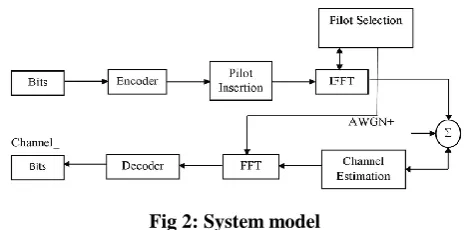
Fig 2: System model
The
transmission model is discussed as below. A set of encoded binary bits transmitted through the underlying channel and the elements taken from code word.The transmitting binary bits are encoded present in the x arethrough the primary channel
International Journal of Innovative Technology and Exploring Engineering (IJITEE) ISSN: 2278-3075, Volume-9 Issue-2, December 2019
matrix. The diagonal matrix given as
X = diag{
x
1N } ,The corresponding code word signal is giveas
=
X +
(1)
Where = ( , ... ) - channel response for all coded
symbols
AWGN noise vector.
Every element with zero mean & with variance . In this ISI( inter-symbol interference)
present. The channel is expected Rayleigh distribution is
followed byDoppler shift . The channel correlation can be definedthroughJake’s spectrum as below
The Bessel function with zero order is given as:
(2)
Where - autocorrelation function
T - symbol duration.
4.1 Efficient Selection Criterion
as pilot positions and in as the pilot positions in and
in A respectually.
, are identified pilot symbols. The encoding through
pilot selections of polar codes is comparable to the subsequent problemhow to estimate in order to produce
for every information vector &the
buildingcircumstances one can instantlydetect.
The above problem has not any solution meanwhile the linear expression only essential length K vector . There are extra
well-known values in in the pilot selectioncase.Those
known pilots are fixed in the information bits are
noted[26].
as pilot positions and in as the pilot positions
in and in A respectually.
, are identified pilot symbols. The encoding through
pilot selections of polar codes is comparable to the subsequent problemhow to estimate in order to produce
for every information vector &the
buildingcircumstances one can instantlydetect.
The above problem has not any solution meanwhile the linear expression only essential length K vector . There are extra
well-known values in in the pilot selectioncase.Those
known pilots are fixed in the information bits are
noted.
Now the procedure of encoding can be given as follows
(3)
The set C has not any longer information set aspresent in the novel encoding. So, the weights of this novel encoding need to betested. Then the encodable recordingrequests to be established efficiently. The elements ofC and the mapping C could be same. This is the first condition.one-to-one mapping is second conditionandit is
invertible.The efficient construction depends on the
fact . The following is happenedwhen .
The following conditions are satisfied for selection pilots efficiently
Condition 1:
Let C ⊆ {1, 2, ...,N} When then . .
Condition:2
Let where . Compared with , all
are increased columns from
Insertion of pilots is not traditionally in this project. In its place of pilot insertion, selection of pilots techniqueis used. The pilots selected whichare cannot be distributed evenly between 1 to Nbit channels.
Two selection schemes are projected based on the effective encoding condition .they are
The uneven pilot selection (UEPS) and
The even pilot selection (EPS).
The new encoding set withselection of pilots from the coded symbols is C = A ∪ Pf, where Pf is containing a set ofselected pilot symbols from the A¯ frozen set. The two UEPS and EPS selectionsare established to meet the effective encoding condition. The condition is GCC = G−1 CC and C is recognized to domination connecting. The efficiency and performance of decoding are explored. The EPS decoding performance is analyzed and displayed by a simulation which isbetter than the insertion of traditional method.
4.2.UNEVEN PILOT SELECTION (UEPS):
Theinvertible matrix is a lower triangular
matrixin which ones present at diagonal in field of binary. Revealssome of the columns are everything zeros
excludingdiagonal elements. The set S is defined as:
S =
(4)
Where is the jth column of the sub matrix , , is a sub
matrix formed by taking rows from .
The pilots selected whichare cannot be distributed evenly between 1 to Nbit channels.
4.3.Even Pilot Selection (EPS)
In this section, Adifferent set D is defined as (5)
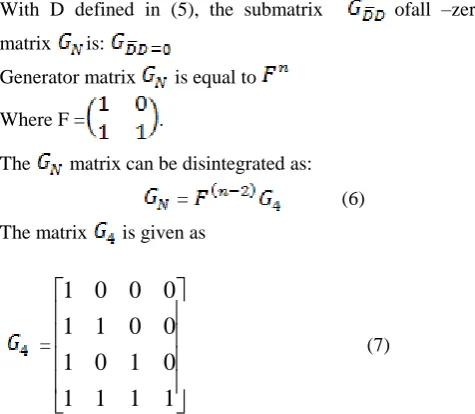
With D defined in (5), the submatrix ofall –zero
matrix is:
Generator matrix is equal to
Where F = .
The matrix can be disintegrated as:
= (6)
The matrix is given as
=
1
1
1
1
0
1
0
1
0
0
1
1
0
0
0
1
(7)
From the abovethe element of 4th position of last column is non- zero. Nowthespecified columns by selectingthrough the set Dremoving the submatrix of .
V. CHANNEL ESTIMATION BASED ON DB-MS Coded symbols are used by the pilot selections. Those coded symbols are known as pilots. The EPS pilot selection and traditional pilot insertion are given below
[image:4.595.47.285.54.261.2]The block diagram for channel encoder is shown in figure 3
Fig 3: Bipolar code basic channel W2
Before proceeding with the polar code we construct and specify a channel W2 which is a Bisymmetric channel and it is to achieve symmetric capacity I(W) which is the highest rate and this is subjected to using the I/P letters of the channel which are equally probable. It is possible to synthesize or create a second set of N binary input channels out of N independent copies of a given B-DMCW channel properties
W
Ni
i
N
. One thing to be noted here is that whenN becomes bigger, 2 things tend to happen i.e. some of the
fraction of channels for the indices I for
I
W
N i is near 0 approaches 1- I(w) and rest of the fraction of channels forindices I for
I
W
N i is near 1 approaches I(w).Thesepolarized channels
W
N i are in good condition for channelcoding. So, one
shouldmakesurethatthechannelswhicharealmostnear1orare1h avetobesentdatathrough rate of 1 and some of the channels for which capacity is 0 needs to send data at rate 0 i.e. the channels with capacity 0 are said to be junk channels. Therefore, Codes implemented on this Idea are called polar codes. We are trying to prove a fact that the real ways exists a sequence of polar codes {Cn; n-1} given any binary discrete memory less channel with I (W) > 0 and any target rate R < I(W). The sequence of polar codes are such that Cn has block length N=2n and the bounding for the successive cancellation
decoder is bounded as
1 4
,
e
P N R
O N
which is
said to be independent of the code rate for the probability of block error under successive cancellation decoding. The complexity of the decoders and encoders that achieve this performance are having a complexity of O (NlogN).
For a Bisymmetric channel W, there are basically two channel parameters of interest. One is the symmetric capacity (W) and the second one is the Bhattacharya parameter.
1 2
log
11
1
1
0
1
2
2
y Y x X
y
W
X
y
I W
W
X
W y
W y
and the Bhattacharyya parameter is given by
12
0
1
y Y
y
y
Z W
W
W
The symmetric capacity parameter is used as a measure of rate and the Bhattacharya parameter is used as a parameter of reliability, respectively. Symmetric capacity is the highest rate at which any reliable communication will take place across the channel W. This will be done using the inputs for the channel W with equal frequency. Bhattacharya parameter is Z(W) is said to be an upper bound on the probability of maximum-likelihood (ML) decision error when W is used only once to transmit either of the two i.e. 0 or 1.
Theperformance of channel estimation analyzed by mean square error (MSE). There are two estimators like least square (LS) and minimum mean square error (MMSE) are used in this estimation. To estimate the channel response the technique linear interpolation is used at non-pilot locations. Let be set of pilot locations then
In the LS estimator, the channel response estimationthrough the pilot locations are given as
=
(13)
International Journal of Innovative Technology and Exploring Engineering (IJITEE) ISSN: 2278-3075, Volume-9 Issue-2, December 2019
(14)
Even though for the MMSE estimation, thechannel response estimation at the pilot locations are:
(
15)
Where is a matrix in which the cross correlation of a and b vectors.
Here
R
ab
E ab
H and I is identity matrix.The MSE of1
ˆ
Nh
estimation does not in common yield a form of closed expressionwithoutanyapproximations and simplifications. The performance of MMSE is better compared to LS in small0
b
E
N
regions.The Numerical results of EPS through MSE and UEPS through MMSE &LS are informed.Thechannel estimation performanceof pilotselection schemesEPS or UEPS should have same as the traditional pilot insertion.The channel estimation performance of UEPS should be worse than the EPS due to the pilots have uneven nature.
VI. RESULTS
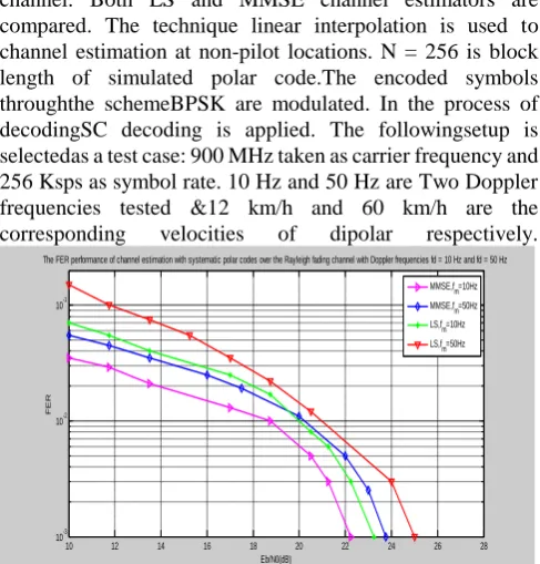
From fig 4: Theexpected channel is to be the Rayleigh fading channel. Both LS and MMSE channel estimators are compared. The technique linear interpolation is used to channel estimation at non-pilot locations. N = 256 is block length of simulated polar code.The encoded symbols throughthe schemeBPSK are modulated. In the process of decodingSC decoding is applied. The followingsetup is selectedas a test case: 900 MHz taken as carrier frequency and 256 Ksps as symbol rate. 10 Hz and 50 Hz are Two Doppler frequencies tested &12 km/h and 60 km/h are the corresponding velocities of dipolar respectively.
10 12 14 16 18 20 22 24 26 28 10-3
10-2 10-1
Eb/N0(dB)
F
E
R
The FER performance of channel estimation with systematic polar codes over the Rayleigh fading channel with Doppler frequencies fd = 10 Hz and fd = 50 Hz
[image:5.595.304.556.50.231.2]MMSE,fm=10Hz MMSE,fm=50Hz LS,fm=10Hz LS,fm=50Hz
Figure 4: The FER performance of channel estimation over the Rayleigh fading channel N=256 and R=0.5.
10 12 14 16 18 20 22 24 26 28
10-3 10-2 10-1
Eb/N0(dB)
F
E
R
The FER performance comparison of the pilot selections of UEPS and EPS
[image:5.595.307.552.377.577.2]UEPS,MMSE EPS,MMSE UEPS,LS EPS,LS
Figure 5: The FER performance comparison of U-EPS and E-PS in the Rayleigh fading channel N=256 and R=0.5.
From fig 5 Theperformance of frame-error-rate (FER) for EPS is shown in below graph. The selected pilots are and = . R = 0.5 is the initial code rate of the polar code. and are the elements in the frozen and information set, respectively. The FER performance of MMSE technique with = 10 Hz isenhancedwhen compared to the LS with the equivalent Doppler shift.When goes up to 50 Hz the MMSE and LS performs worse FER performance than the consistent performance at 10HZ.
10 12 14 16 18 20 22 24 26 28
10-3 10-2 10-1
Eb/N0(dB)
F
E
R
The FER performance comparison of the pilot selections (UEPS and EPS)
[image:5.595.47.291.397.652.2]UEPS,MMSE EPS,MMSE Traditional,MMSE UEPS,LS EPS,LS Traditional,LS
Figure 6: FER performance comparison among pilot selections and traditional pilot insertion method
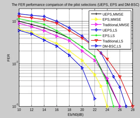
From fig 6 A comparison between the UEPS and EPS pilot selections and the insertion of pilot traditionally shown in the following graphs. Where = 50 Hz is the Doppler shift. In this pilot insertion scheme, pilots are injectedevenly. For each four coded symbolsone pilot is inserted. The polar code with block length N = 256 isused for the pilot insertion and 0.5 is the initial code rate. The numbers of pilots in these three systems areequal.The total number of pilots employed here is 64. In the traditional pilot insertion the overall throughput is = 128/(256 + 64) that equal to 0.4. The same throughput is maintainedby UEPS and EPS as that of the insertion of pilot in traditional method, the initial code rate is adjustedasR = 147/256 = 0.574. For both UEPS
final throughput of = (147 − 45)/256 = 0.4.When MMSE is applied to UEPS and the traditional method has nearly the equal FER performance and the FER performance of EPSis better when compared to UEPS and traditional insertion. Thus benefit of EPS than UEPS at FER applies at 2dB to the traditional selection of pilots. But, this benefit of EPS terminated the traditional insertion comes that all pilots injected serve only as the elements of channel estimation.
10 12 14 16 18 20 22 24 26 28
10-3 10-2 10-1
Eb/N0(dB)
F
E
R
The FER performance comparison of the pilot selections (UEPS, EPS and DM-BSC)
[image:6.595.47.285.157.357.2]UEPS,MMSE EPS,MMSE Traditional,MMSE UEPS,LS EPS,LS Traditional,LS DM-BSC,LS
Figure 7: Bisymmetrical channel estimation Vs EPS and UEPS
VII. CONCLUSIONS
Two pilot selection systems, uneven pilot selection (UEPS) and even pilot selection (EPS) are considered for polar codes along with new DM-BSC in fading channels.Instead of pilot insertion, thedecodingperformanceof polar codes is really improved by choosing the pilots. Considering the insufficient performance of polar codes in the fixed domain, the projected pilot selection system EPS can be hired in real systems for channel estimation or tracing. Simulation results display that the projected EPS systembeats both UEPS and traditional insertion of pilot systems.so, the polar code performance is improved in wireless communication systems.
REFERENCES
1. EArikan, “Channel Polarization: A Method for Constructing Capacity- Achieving Codes for Symmetric Binary-Input Memoryless Channels,” IEEETransactions on InformationTheory, vol55, no7, pp30513073,2009.
2. RMori.etc.al,“Performance of polarcodes with theconstruction using densityevolution,” IEEECommunicationsLetters, vol3, no7,pp519–521,Jul2009.
3. ITal.etc.al, “How to Construct Polar Codes,” InformationTheory, IEEETran’s ,vol59, no10, pp6562–6582, Oct2013.
4. PTrifonov.etc.al, “Efficient Design and Decoding of Polar Codes,” IEEE Tran’s on Communications, vol60, no11, pp3221–3227, November2012
5. DWu.etc.al, “Construction and Block Error Rate Analysis of Polar Codes Over AWGN Channel Based on Gaussian Approximation,” IEEE Commun’s-Letters, vol18, no7, pp1099–1102, Jul2014.
6. KChen.etc.al,“Improved SuccessiveCancellation Decoding ofPolar Codes,”IEEE-Tran’s onCommun’s, vol61, no8, pp3100–3107, August2013.
7. Ital.etc.al, “List Decoding of Polar Codes,” InformationTheory, IEEETran’s, vol61, no5, pp2213–2226, May2015.
8. EArikan,“APerformanceComparisonofPolarCodesandReed-Mullercode s,”IEEECommunicationsLetters,vol12,no6,pp447–449,200
9. NHussami.etc.al,“Performance of PolarCodes for Channeland Source Coding,” in IEEEIS-IT, June2009, pp1488–1492.
10. JGuo.etc.al,“Enhanced BeliefPropagation Decodingof PolarCodes throughConcatenation,” in 2014 IEEEISIT,2014 pp29872991. 11. EArikan, “Systematic Polar Coding,” IEEECommun’sLetters, vol.
15,no8, pp860–862, August2011.
12. YLi, “Pilot-symbol-aided channel estimation for ofdm in wireless systems,” IEEE Tran’s onVehicularTechnology, vol49, no4, pp12071215, Jul2000.
13. MMorelli.etc.al,“A Comparisonof PilotAided ChannelEstimation Methods for OFDMSystems,” IEEETransa’s SignalProcessing, vol. 49, no12, pp3065–3073, Dec2001.
14. YLi, “Simplified channel estimation for ofdm systems with multiple transmit antennas,” IEEE-Transa’s on Wireless-Commun’s, vol1,no1,pp67–75,Jan2002.
15. KJKim.etc.al,“Akalman filterbased detection and channelestimation algorithm for mimoofdm systems,” IEEETransa’s WirelessCommun’s, vol4, no2, pp710–721, March2005.
16. HMinn.etc.al,“Optimal trainingsignals for mimoofdm channelestimation in the presenceof frequencyoffset and phasenoise,” IEEETransa,onCommuni’s, vol54, no10, pp1754–1759, Oct2006. 17. MBiguesh.etc.al,“Trainingbased mimochannel estimation: a studyof
estimator tradeoffsand optimal trainingsignals,” IEEETransa’s on SignalProcessing, vol54, no3, pp884–893, March2006.
18. 3GP-PTM,“TechnicalSpecification Group RadioAccess Network; (Release10),”3GPPTS 36.211V1070(201302).
19. LLi.etc.al,“On the EncodingComplexity of SystematicPolarCodes,” in IEEESO-CC, Sep2015, pp508–513.
20. GSarkis.etc.al,“Flexible and LowComplexity Encodingand Decoding of SystematicPolarCodes,” IEEETransa’sonCommun’s, vol64, no7, pp2732–2745, June2016.
21. AEslami.etc.al,“On BitErrorRate Performanceof PolarCodes inFinite Regime,” conference on Computingcommmn’s.2010,pp188–194. 22. “A Practical Approach to Polar Codes,” in IEEEInternational
Symposiumon InformationTheory, 2011, pp16–20.
23. YS Cho.etc.al, Practical guide with matlab based on mimo-ofdm JohnWiely-Asia-2010
24. K.Murali, Siva Perumal.S“ Power Signal based Multiple-Access Schemes for 5G and Beyond- Survey and its Challenges”Journal of Adv Research in Dynamics and Control Systems,April 2019,pp 184-191 25. K.Murali,K.Prasuna “Survey on Saliency-Based Approach of Error
Correction for 5G Communication” Smart Intelligent Computing and Applications Proceedings of the Third International Conference on Smart Computing and Informatics, Volume 2,Pp 511-516 https://doi.org/10.1007/978-981-32-9690-9_56
![SYNTHESIS AND BIOLOGICAL SCREENING OF 2 AMINO 6 ARYL 4 {[(3′ DIFLUOROMETHOXY) 5′ (3″ METHYL) 4″ (2‴,2‴,2‴ TRIFLUOROETHOXY)PYRIDIN 2″ YL]METHOXYPHENYL} NICOTINONITRILES](data:image/gif;base64,R0lGODlhAQABAIAAAP///wAAACH5BAEAAAAALAAAAAABAAEAAAICRAEAOw==)