University of Strathclyde
Department of Electronic and Electrical Engineering
Facilitating the Validation of Adaptive Power
System Protection through Formal Scheme
Modelling and Performance Verification
Ibrahim Faiek Abdulhadi
A thesis presented in fulfilment of the requirements for the
degree of Doctor of Philosophy
This thesis is the result of the author's original research. It has been composed by the author and has not been previously submitted for examination which has led to the award of a degree.
The copyright of this thesis belongs to the author under the terms of the United Kingdom Copyright Acts as qualified by University of Strathclyde Regulation 3.50. Due acknowledgement must always be made of the use of any material contained in, or derived from, this thesis.
All praise to God for his endless guidance and sustenance
Acknowledgments
First and foremost I would like to express my thanks and gratitude to my supervisor Prof. Graeme Burt for his support and guidance during my studies. The challenges you continuously posed to my research definitely helped increase its quality. You always made me go the extra mile!
I would like to extend my thanks to my second supervisor Dr. Adam Dyśko. You always managed to provide an interesting and entertaining technical conversation.
Thanks to Dr. Ray Zhang of National Grid. I appreciate you facilitating my placement at the company and supporting my research work.
Thanks also go to the EPSRC for providing the financial support for this work and facilitating a UK forum for disseminating my research achievements.
I would also like to thank my colleagues in the department of electronic and electrical engineering whom with I had valuable research exchanges. Special thanks go to those who tolerated my cynicism on various topics of life.
Thanks to my brother for appreciating the comic value of my PhD experience and listening intently to related rants.
Abstract
There exists a critical mass in research related to adaptive protection approaches that address some of the shortcomings of conventional protection functions. This is in response to concerns in the reliability of conventional protection which manifested itself in some severe disturbances in more recent years. Despite the fact that adaptive protection offers a compelling technical solution to some of these performance problems, the industry has not widely adopted adaptive protection approaches as a de facto policy for future protection scheme implementations.
This is attributed to the difficulties associated with the testing of such schemes where no significant work has been reported yet. Furthermore, the benefits vs. the risks associated with such a protection strategy are not well understood. This is coupled with the conservatism towards radical changes in the way the power system is operated. As such the work reported in this thesis complements the existing body of research in order to address some of the major technical and institutional challenges associated with adopting adaptive protection schemes for future networks, especially those networks that exhibit flexibility in operation to deal with uncertainty in generation and to maximise asset utilisation. These are network characteristics that adaptive protection approaches are seen to be an effective enabler of.
Contents
1
Introduction ... 25
1.1 Research context and justification ... 25
1.2 Research main hypothesis and contributions... 27
1.3 Publications ... 28
1.4 Thesis outline ... 30
1.5 References ... 32
2
A Modern Perspective on Power System Protection ... 33
2.1 Chapter methodology and contributions ... 33
2.2 Power system protection principles ... 34
2.2.1 Unit-based protection ... 34
2.2.2 Non-unit based protection ... 36
2.3 Distance protection ... 37
2.3.1 Elements, characteristics and polarisation ... 37
2.3.2 Ground fault detection ... 41
2.3.3 Communications based distance schemes ... 42
2.3.4 Distance protection application issues and considerations ... 43
2.4 DER interface protection ... 45
2.4.1 Loss of mains protection ... 45
2.5 System integrity protection schemes ... 46
2.6 Wide area measurement, protection, automation and control ... 47
2.6.1 Synchrophasor measurement technology ... 47
2.6.2 Protection applications of SMT ... 48
2.7 The digital substation ... 49
2.7.2 IEC 61850 communications standard ... 52
2.8 Functional testing of power system protection ... 54
2.8.1 Functional type testing ... 54
2.8.2 Software type testing ... 55
2.8.3 Commissioning testing ... 56
2.8.4 Shortfalls of existing testing practices ... 56
2.9 Chapter summary... 57
2.10 References ... 57
3
Evaluating the Performance of Existing Protection Schemes
under Flexible Primary System Operation ... 61
3.1 Chapter methodology and contributions ... 61
3.2 Causes of deterioration in protection performance under flexible power system operation ... 64
3.2.1 Flexible operation of the primary power system ... 64
3.2.2 Power system topology changes ... 65
3.2.3 Utilisation of DER ... 67
3.2.4 FACTS and similar devices providing system operational support67 3.2.5 Wide-area disturbances ... 68
3.2.6 Hidden failures ... 68
3.2.7 Closing discussion on performance issues ... 69
3.3 Overview of quadrature booster transformers ... 70
3.3.1 QB construction, connection arrangements and functions ... 70
3.3.2 QB control and protection arrangements ... 72
3.3.3 Setting of distance protection for transmission lines with QBs ... 74
3.4 The evaluation of the impact of QBs on distance protection
performance ... 75
3.4.1 Evaluation methodology ... 75
3.4.2 QB model... 76
3.4.3 Results of the distance protection reach evaluation ... 78
3.4.4 Discussion of reach impact due to QB operation ... 87
3.4.5 A relation for measured impedance error vs. QB mode ... 88
3.5 Sensitivity and stability evaluation of loss of mains protection ... 93
3.5.1 Methodology ... 94
3.5.2 Power system models ... 96
3.5.3 Compromise settings for DFIG based generation ... 97
3.5.4 Performance discrepancies between different ROCOF algorithms 97 3.6 Robust vs. flexible protection scheme performance ...100
3.6.1 Robust behaviour of protection systems ...100
3.6.2 The need for flexible power system protection ...101
3.6.3 Robustness in protection measurement algorithms ...103
3.7 Chapter summary...104
3.8 References ...105
4
Delivering Flexible Protection Schemes with Enhanced
Performance using an Adaptive Protection Philosophy ... 109
4.1 Chapter methodology and contributions ...109
4.2 Adaptive protection concept review ...111
4.2.1 Identification of prevailing power system conditions ...111
4.2.2 Adaptable protection functions ...113
4.2.3 Automatic adjustments of protection functions ...115
4.3.1 Adaptive protection to improve scheme sensitivity ...117
4.3.2 Adaptive protection to improve scheme coordination ...119
4.3.3 Shaping the research direction for adaptive protection ...120
4.4 Challenges to adopting adaptive protection ...121
4.4.1 Integration with existing protection arrangements ...121
4.4.2 Adaptive scheme testing ...122
4.4.3 Inadequacy of utility policies and procedures ...122
4.5 Using settings groups to enhance distance protection performance in QB presence ...124
4.5.1 General strategy for the adaptive distance protection scheme ...124
4.5.2 Settings group calculation and mapping to power system states 126 4.5.3 Settings group for a fall back situation ...131
4.5.4 Settings group selection implementation with a physical relay ...132
4.6 Choosing the number of settings groups for adaptive protection ...134
4.7 Chapter summary...136
4.8 References ...137
5
Requirements specification, architectural design and overall
validation of adaptive protection schemes ... 140
5.1 Chapter methodology and contributions ...140
5.2 Overview of adaptive protection design and architectures ...141
5.3 Adaptive protection lifecycle requirements ...143
5.3.1 Scheme design and implementation requirements ...145
5.3.2 Scheme installation and commissioning requirements ...146
5.3.3 Scheme operation and maintenance requirements ...147
5.4 Development of a detailed adaptive protection architecture ...150
5.4.1 The role of execution layer functions ...150
5.4.2 The role of coordination layer functions ...153
5.4.3 The role of management layer functions ...154
5.5 Design and implementation of the proposed adaptive distance protection scheme ...156
5.5.1 Primary ‘system state acquisition’ function ...159
5.5.2 ‘Online protection performance verification’ function ...160
5.5.3 ‘New protection configuration selection’ function ...161
5.5.4 ‘New protection configuration activation and verification’ function . ...162
5.5.5 Implemented communications interfaces ...162
5.5.6 Management layer functions implementation ...163
5.6 Hardware in the loop (HIL) adaptive distance protection scheme validation ...164
5.6.1 HIL validation methodology ...164
5.6.2 HIL validation results...165
5.6.3 Discussion of HIL validation results in light of APA design and scheme implementation ...172
5.7 The role of hardware in the loop approach to validating adaptive protection schemes ...174
5.8 Chapter summary...175
5.9 References ...176
6
Formal approach to the verification of adaptive protection
scheme performance based on hybrid systems modelling ... 178
6.1 Chapter methodology and contributions ...178
6.2.1 Hybrid dynamical systems overview ...180
6.2.2 Modelling power systems in the hybrid domain ...181
6.3 Verification of hybrid systems performance ...183
6.3.1 The use of reachability analysis to verify hybrid system safety ...184
6.3.2 Justification for conducting reachability analysis for adaptive protection safety verification ...185
6.4 Defining a hybrid model for the developed adaptive distance protection scheme ...186
6.4.1 Developing a DES abstraction to include adaptive protection functionality ...186
6.4.2 Definition of operation and performance states as a prerequisite for reachability analysis ...194
6.5 Reachability analysis for the verification of the developed adaptive distance protection logic ...195
6.5.1 Reachability verification implementation in Simulink ...197
6.5.2 Reachability analysis test setup and results ...201
6.6 Discussion of reachability results and the role of formal approaches to the verification of adaptive protection functionality ...205
6.7 Chapter summary...206
6.8 References ...207
7
Thesis Conclusions and Future Work ... 209
7.1 Qualitative reflection on the general hypothesis ...209
7.2 Evaluation of conventional protection performance ...209
7.3 Design of adaptive protection schemes ...211
7.6 Future work ...215
Appendix A
Test transmission network model data and
protection settings ... 216
Appendix B
Adaptive Distance Protection Simulink Model . 218
List of Figures
Figure 2-1 A typical current differential protection scheme showing zone of
protection ... 35
Figure 2-2 Radial distribution network showing grading between IDMT characteristics to achieve selectivity between overcurrent protection relays ... 36
Figure 2-3 Mho distance protection characteristic ... 39
Figure 2-4 Quadrilateral characteristic showing independently adjustable resistive and reactive reaches ... 40
Figure 2-5 Distance protection zones ... 40
Figure 2-6 Zone 2 coordination with shortest adjacent line ... 41
Figure 2-7 Load blinders used to minimise load encroachment ... 43
Figure 2-8 Distance protection of multi-terminal circuits ... 44
Figure 2-9 Typical WAMPAC architecture ... 48
Figure 2-10 IED hardware architecture ... 49
Figure 2-11 Typical PSL diagram ... 51
Figure 2-12 IEC 61850 functional hierarchy ... 52
Figure 2-13 Typical substation architecture utilising IEC 61850 ... 53
Figure 2-14 Dynamic type testing of protection relays ... 55
Figure 3-1 Schematic showing QB shunt and series elements ... 70
Figure 3-2 QB phasor diagram showing primary system quantities incorporating QB action ... 71
Figure 3-3 QB substation connection arrangement ... 72
Figure 3-4 Typical QB operating envelope ... 73
Figure 3-5 Typical QB local control system ... 73
Figure 3-6 Modelled primary system single line diagram showing QB positions ... 76
Figure 3-7 QB in extended delta winding connection ... 77
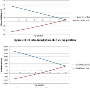
Figure 3-8 QB introduced phase shift vs. tap position ... 77
Figure 3-9 Circuit power flow vs. QB tap position ... 77
Figure 3-12 Fault impedance when QB is in buck mode ... 87
Figure 3-13 Mho characteristic showing how the reach error magnitude is measured ... 90
Figure 3-14 Mho diagram illustrating process of determining |Zoffset| ... 92
Figure 3-15 LOM sensitivity and stability testing procedure ... 95
Figure 3-16 33kV test network ... 96
Figure 3-17 11kV Test network ... 96
Figure 3-18 Maximum sensitivity settings for 30MVA synchronous DG connected to 33kV network – relay 1 ... 98
Figure 3-19 Maximum sensitivity settings for 30MVA synchronous DG connected to 33kV network - relay 2 ... 98
Figure 3-20 Maximum sensitivity settings for 30MVA synchronous DG connected to 33kV network - relay 3 ... 99
Figure 3-21 Primary current trajectory under normal operating conditions ...101
Figure 3-22 Flexible changes in protection setting and new system current trajectory ...102
Figure 4-1 Adaptive protection scheme composition ...115
Figure 4-2 Adaptive distance protection general strategy ...126
Figure 4-3 Phase to phase fault impedance locus mapping on Mho diagram with different QB modes, tap positions and fault positions ...127
Figure 4-4 Mho diagram showing extended zone 2 (AZ) for QB boost mode ....128
Figure 4-5 Mho diagram showing extended zone 2 (AZ) for QB buck mode to fully offset under reach issue ...129
Figure 4-6 Mho diagram showing extended zone 2 (AZ) for QB buck mode to partially offset under reach issue ...129
Figure 4-7 Mho diagram showing extended zone 3 (AZ) for QB buck mode ...130
Figure 4-8 Settings group selection implementation ...132
Figure 4-9 Alstom P446 PSL for settings group selection ...133
Figure 4-10 Using IEC 61850 for selecting between a large number of settings groups ...134
Figure 5-1 Original proposed adaptive protection architecture ...141
Figure 5-3 Behaviour of adaptive scheme under SCT and normal operating
modes ...146
Figure 5-4 V-Model for the V&V of a system’s design and implementation ...149
Figure 5-5 Developed adaptive protection architecture ...151
Figure 5-6 High level structure of the Simulink model and interaction with testing ...157
Figure 5-7 Adaptive distance protection scheme implementation ...158
Figure 5-8 Physical equipment used for HIL testing of the adaptive distance protection scheme ...159
Figure 5-9 QB connection and mode state acquisition ...160
Figure 5-10 Initiating or blocking settings changes based on reach error for a given QB state ...161
Figure 5-11 Settings activation low level implementation ...162
Figure 5-12 Test network showing fault positions and distance protection relay ...165
Figure 5-13 Test case 1, adaptive protection disabled ...166
Figure 5-14 Test case 1, adaptive protection enabled ...166
Figure 5-15 Test case 1, IED disturbance record ...166
Figure 5-16 Test case 2, adaptive protection disabled ...167
Figure 5-17 Test case 2, adaptive protection enabled ...167
Figure 5-18 Test case 2, IED disturbance record ...168
Figure 5-19 Test case 3, adaptive protection disabled ...168
Figure 5-20 Test case 3, adaptive protection enabled ...169
Figure 5-21 Test case 3, IED disturbance record ...169
Figure 5-22 Test case 4, adaptive protection disabled ...170
Figure 5-23 Test case 4, adaptive protection enabled ...170
Figure 5-24 Test case 4, IED disturbance record ...170
Figure 5-25 Test case 5, adaptive protection disabled ...171
Figure 5-26 Test case 5, adaptive protection enabled ...171
Figure 5-27 Test case 5, IED disturbance record ...172
Figure 6-3 Finite state machine representing operating states of protection
element ...187
Figure 6-4 Interactions between continuous and discrete components of system under study ...191
Figure 6-5 DES abstraction representing adaptive protection functionality and its relation to conventional protection elements and the underlying primary system ...192
Figure 6-6 Finite automata reflecting primary plant states ...193
Figure 6-7 Partitioning of the hybrid state space ...194
Figure 6-8 Reachability analysis procedure...197
Figure 6-9 Reachability analysis subsystem ...198
Figure 6-10 Stateflow subsystem for reachability analysis showing three categories under test ...199
Figure 6-11 Reach performance Stateflow state diagram (automaton) ...200
Figure 6-12 Load encroachment performance Stateflow state diagram ...200
Figure 6-13 Adjacent line coordination performance Stateflow diagram ...201
Figure 6-14 Structure of the Simulink test harness for performing reachability analysis ...202
Figure 6-15 QB states for stimulating the adaptive protection logic using a PRBS ...202
Figure 6-16 Correct operation of adaptive logic indicated by safe states ...203
Figure 6-17 Failure of adaptive logic leading to unsafe state detection ...204
Figure B-1 Full high level Simulink model showing constituent subsystems ....218
Figure B-2 Signal generator for testing the model ...219
Figure B-3 Coordination layer subsystems ...220
Figure B-4 Primary system state acquisition subsystems ...221
Figure B-5 Stateflow chart to determine QB state based on status measurements ...221
Figure B-6 Stateflow chart used to determine line loading state based on status measurements ...222
Figure B-7 Protection performance verification subsystem ...223
Figure B-9 Setting activation and verification subsystem ...225
Figure B-10 Reachability analysis signal mapping subsystem ...226
Figure B-11 Staeflow chart mapping QB state and protection setting for reachability analysis ...227
Figure B-12 Management layer functionality ...227
Figure B-13 Reachability analysis subsystem ...227
Figure C-1 Transmission circuit used for load encroachment ...228
List of Tables
List of abbreviations
AEZ Anti-Encroachment Zone
ANN Artificial Neural Network
APA Adaptive Protection Architecture
COMTRADE Common format for Transient Data Exchange
CT Current Transformer
CVT Capacitive Voltage Transformer
DAR Delayed Auto Reclose
DER Distributed Energy Resources
DES Discrete Event System
DFIG Doubly Fed Induction Generator
DG Distributed Generation
DMS Distribution Management System
DNP3.0 Distributed Network Protocol 3.0
DO Data Object
DT Definite Time
DUT Device Under Test
EMC Electro Magnetic Compatibility
EMS Energy Management System
FACTS Flexible AC Transmission Systems
FCL Fault Current Limiter
GOOSE Generic Object Oriented Substation Event
GPS Global Positioning System
HDS Hybrid Dynamical System
HIL Hardware in the Loop
HMI Human Machine Interface
ICT Information and Communications Technology
IDMT Inverse Definite Minimum Time characteristic
IED Intelligent Electronic Device
LAN Local Area Network
LED Light Emitting Diode
LN Logical Node
LOM Loss of Mains
MAS Multi Agent System
MTTR Mean Time to Repair
MU Merging Unit
NCIT Non-Conventional Instrument Transformer
OLTC On Load Tap Changer
OPC Object Linking and Embedding for Process Control
PC Personal Computer
PCC Point of Common Coupling
PRBS Pseudo Random Binary Sequence
PSL Programmable Scheme Logic
PSO Particle Swarm Optimisation
PST Phase Shifting Transformer
QB Quadrature Booster
QBCS Quadrature Booster Control System
RCA Relay Characteristic Angle
ROCOF Rate of Change of Frequency
RTDS Real Time Digital Simulator
SCL Substation Configuration Language
SCT Site Commissioning Test
SG Setting Group
SGCB Settings Group Control Block
SIPS System Integrity Protection System
SMT Synchrophasor Measurement Technology
SV Sampled Value
V&V Verification and Validation
VS Voltage Vector Shift
VT Voltage Transformer
WAMPAC Wide Area Measurement, Protection and Control
WAMS Wide Area Measurement System
List of symbols
Ground fault zero sequence compensation factor
Ground fault residual compensation factor
Reach error magnitude (Ω)
Reach error threshold (Ω)
Zero sequence current (A)
Residual current (A)
Zero sequence impedance (Ω)
Positive sequence impedance (Ω)
Zero sequence resistance (Ω)
Positive sequence resistance (Ω)
Zero sequence reactance (Ω)
Positive sequence reactance (Ω)
Zero sequence susceptance (S)
Positive sequence susceptance (S)
Positive sequence source impedance (Ω)
Hybrid system automaton
Set of discrete states
Primary power system operational state
Conventional protection system operational state
Set of hybrid system inputs
Set of initial hybrid system states
Discrete state domain
Set of edges/transition maps
Continuous vector field
Set of guard conditions
Continuous state reset relation
Discrete state n
Set of real numbers
Active setting n
State transition n
̅ Unsafe state space
Invariant performance state
Load encroachment threshold current ( ) Monitored system quantities
̃, - Event related to monitored system quantities
̃, - Protection event
( ) Protection command
Eventually logical operator
Always logical operator
1
Introduction
1.1 Research context and justification
pproaches to power system protection are under scrutiny for mal-operation and shortcomings in performance which leave the power system exposed during dynamic and stressed system operating conditions. The dynamic system operation and the uncertainties brought with it were some the main focuses of the research consortium SUPERGEN FlexNet that funded the research reported in this thesis. These operational challenges have been echoed by the protection research community that identified a number of issues that affect the performance of protection schemes. Such issues include:
Topological changes in the power system and transmission and distribution levels result in changes in fault levels that affect the operating times or even the sensitivity of protection or changes fault paths that affect the coordination of protection [1, 2].
The impact of power electronic generator and energy storage interfaces on the fault levels seen by protection which can affect their sensitivity especially in islanded power system operation [3, 4].
Operating the power system with lower inertia due to the connection of large levels of wind generation, in addition to the increased utilisation of the transmission network can result in more forceful system disturbances. This can affect the performance of system protection especially those relying on system frequency to operate [5, 6].
One of the approaches to improve the protection functionality, as proposed in the literature, relies on adaptive techniques. These involve dynamic changes in the protection functionality to reflect the state of the power system at any given time. These dynamic changes in protection configuration are governed by specially designed and often bespoke logic. This logic can rely on simple mappings between system states and new protection configurations or more complex arrangements that utilise intelligent systems or optimisation techniques [7, 8]. System operators are also expressing interest in adaptive protection. Smart grid projects funded by the low carbon network fund (LCNF) scheme consider adaptive protection in their demonstration [9]. But the more pressing issue is that the philosophy of adaptive protection was never fully embraced by the power system operators despite the clear performance enhancements that they provide and the clear need to achieve such improvement in performance.
There are some fundamental problems related to adaptive protection that are not being addressed sufficiently or are being outright ignored. For instance, issues related to testing the adaptive schemes out with a set of very specific case studies are rarely discussed. No standard or widely accepted approaches to testing exist. Furthermore, the requirements development for adaptive protection schemes is fairly basic despite it being an important prerequisite for scheme validation and verification. Furthermore, it is important to consider the implications of gradually introducing more adaptive protection schemes alongside more conventional approaches to protection. As such, there must be strategies for non-intrusive integration of these protection schemes to substations as well appropriate revisions for related utility policies.
How much flexibility can adaptive protection provide and where can it be applied without adding an unmanageable level of uncertainty to the power system operation?
How can adaptive protection functions be integrated in a substation without the need for an overhaul in protection scheme design or equipment?
How should the testing methodology for adaptive protection be approached in order to de-risk the behaviour of such schemes?
1.2 Research main hypothesis and contributions
The following statements describe the main research hypothesis:
Power systems that are operated in a flexible manner necessarily require protection schemes that display flexible operating characteristics. Adaptive protection techniques strategically integrated within substations can deliver the required level of flexible operation without jeopardising required performance levels.
From these statements, a number of sub-hypotheses are examined throughout the course of this thesis:
Existing protection scheme testing practices are not sufficiently effective in validating the overall adaptive scheme functionality and existing practices must be complemented but not completely revamped.
In order to de-risk the adaptive protection functionality, a description of its behaviour is required such that it takes into account the state of the power system, the configuration of the protection scheme and dynamic interactions between both systems.
The development of a lab based adaptive protection using commercial distance protection functions and substation automation equipment served as a vehicle to test the hypotheses made earlier. To this end, four main novel contributions have been made. These are:
An experimentally validated adaptive distance protection scheme has been developed. It is based on dynamic settings group selection to improve the performance of distance protection in the presence of quadrature booster transformers (QB). This provides an improvement in reach of up to 20% for distance zones that are affected by the under-reach effect of the QB.
The adaptive protection architecture proposed in previous work, which is adopted by the developed adaptive distance protection scheme, was formalised and validated using a system’s engineering approach. This considered the functional requirements of an adaptive protection scheme over its lifecycle and utilised model based design using Simulink to create platform independent adaptive protection functions.
Limitations in the standard method of hybrid modelling abstraction (which is used in this thesis to model the behaviour of the adaptive protection) were overcome. This was achieved by extending the behavioural model to accommodate concurrent control loops which encompasses the adaptive protection functionality.
A powerful approach to formally verify the logic of adaptive protection schemes has been demonstrated. This method is based on a novel application of reachability analysis (safety property verification) to adaptive protection that utilises the developed hybrid behavioural model.
1.3 Publications
Journal articles:
A. Roscoe, I. Abdulhadi, G. Burt, “P and M Class Phasor Measurements Unit Algorithms using Adaptive Cascaded Filters,” IEEE transactions on Power Delivery, 2013.
Conference papers:
I. Abdulhadi, R. M. Tumilty, G. M. Burt, and J. R. McDonald, “A dynamic modelling environment for the evaluation of wide area protection systems,”
in Universities Power Engineering Conference, 2008. UPEC 2008. 43rd
International, 2008, pp. 1–5.
I. Abdulhadi, G. M. Burt, A. Dysko, R. Zhang, and J. Fitch, “The evaluation of distance protection performance in the presence of Quadrature Boosters in support of a coordinated control strategy,” in Developments in Power System Protection (DPSP 2010). Managing the Change, 10th IET International
Conference on, 2010, pp. 1–5.
I. Abdulhadi, F. Coffele, A. Dysko, C. Booth, and G. Burt, “Adaptive Protection Architecture for the Smart Grid,” in Innovative Smart Grid Technologies (ISGT
2011). 2011, pp. 1–8.
S. P. Le Blond, R. K. Aggarwal, I. F. Abdulhadi, and G. M. Burt, “Impact of DFIG windfarms and instrument transformers on transient based protection,” in Developments in Power System Protection (DPSP 2010). Managing the Change,
10th IET International Conference on, 2010, pp. 1–5.
J. Kincaid, I. Abdulhadi, A. Emhemed, G. Burt, “Evaluating the Impact of Superconducting Fault Current Limiter on the Performance of Distribution Network Protection Schemes,” in Universities Power Engineering Conference,
2011. UPEC 2011. 46th International, 2011, pp. 1-6.
V. Terzija, P. Regulski, L. P. Kujunmuhammed, B. C. Pal, G. Burt, I. Abdulhadi, T. Babnik, M. Osborne, W. Hung, “FlexNet Wide Area Monitoring System,” in
IEEE PES General Meeting, 2011, pp. 1-7.
Roscoe, I. Abdulhadi, G. Burt, “P-Class Phasor Measurement Unit Algorithms Using Adaptive Filtering to Enhance Accuracy at Off-Nominal Frequencies,” in
X. Cao, I. Abdulhadi, C. Booth, G. Burt, “Defining the Role of Wide Area Adaptive Protection in Future Networks”, in Universities Power Engineering
Conference, 2011. UPEC 2011. 47th International, 2012, pp. 1-6.
I. Abdulhadi, F. Coffele, A. Dysko, C. Booth, G. Burt, G, Lloyd, B. Kirby, “Performance Verification and Scheme Validation of Adaptive Protection Schemes”, in CIGRE 2012 Session, 2012, pp. 1-9.
A. Adrianti, I. Abdulhadi, A. Dysko, G. Burt, “Assessing the reliability of adaptive power system protection schemes”, in Developments in Power
System Protection (DPSP 2012). 11th IET International Conference on, 2012,
pp. 1-6.
L. Xiong, I. Abdulhadi, G. Burt, “Adaptive Load Blinder for Maximising Distance Protection Loadability,” PACWorld 2013.
National and international reports:
DERlab, “International White Book on DER Protection: Review and Testing Procedures”, 2011.
Energy Network Association, “ETR 139:2009, Recommendations for the Setting of Loss of Mains Protection Relays”, 2009.
1.4 Thesis outline
The remainder of the thesis chapters are laid out as follows:
Chapter 3 – claims of conventional protection performance shortfalls have been substantiated in this chapter through a combination of literature review, simulations and laboratory testing. The chapter focuses on protection performance issues that stem from the varied and flexible operation of future power systems. Simulations conducted have quantified the effect quadrature booster transformers have on the reach of distance protection. Furthermore, the performance of loss of mains protection (mainly ROCOF) was evaluated using secondary injection testing. The chapter finally asserts that to overcome protection performance challenges caused by flexible power system operation a flexible approach to protection is required.
Chapter 4 – this chapter reviews adaptive protection methods as an approach to provide the required flexibility for protection scheme functionality and thus enhance its performance. This review focuses on adaptive protection techniques that improve the selectivity or coordination of protection schemes. By recognising the technical and institutional challenges facing the adoption of an adaptive protection strategy, the chapter identifies the scope adaptive protection functionality where it is considered most applicable. The chapter finally provides a preliminary design for an adaptive distance protection scheme based on multiple settings groups to address problems identified in the previous chapter.
Chapter 5 – a systems engineering based approach to adaptive protection is presented here. It focuses on developing life-cycle functional requirements for adaptive protection schemes which are reflected in a formalised adaptive protection architecture. An architecture compliant design and implementation of the adaptive distance protection scheme is presented. Hardware in the loop testing is used to validate the scheme in full view of the developed requirements and architecture.
using this behavioural representation to extract a measure of adaptive protection performance (adaptive protection safety) and verify it using reachability analysis. The adaptive setting logic used by the distance protection scheme developed in the thesis was verified using reachability analysis.
Chapter 7 – the main thesis conclusions are presented in this chapter with a focus on contributions made to the power system protection community and the systems verification body of research. Future directions of research have also been identified with focus on applying the modelling and testing methodologies developed in this thesis to wide area protection schemes.
1.5 References
[1] F. Coffele, C. Booth, G. Burt, C. McTaggart, and T. Spearing, "Detailed Analysis of the Impact of Distributed Generation and Active Network Management on Network Protection Systems," in CIRED 2011, 2011. [2] D. Tholomier and A. Apostolov, "Adaptive protection of transmission
lines during wide area disturbances," in Power Systems Conference and
Exposition, 2009. PSCE '09. IEEE/PES, 2009, pp. 1-7.
[3] E. Sortomme, G. J. Mapes, B. A. Foster, and S. S. Venkata, "Fault analysis and protection of a microgrid," in Power Symposium, 2008. NAPS '08. 40th
North American, 2008, pp. 1-6.
[4] M. A. Zamani, T. S. Sidhu, and A. Yazdani, "A Protection Strategy and Microprocessor-Based Relay for Low-Voltage Microgrids," IEEE
Transactions on Power Delivery, vol. 26, pp. 1873-1883, 2011.
[5] NGET, "Report of the national grid investigation into the frequency deviation and automatic demand disconnection that occured on the 27th May 2008," 2009.
[6] R. Doherty, A. Mullane, G. Nolan, D. J. Burke, A. Bryson, and M. O'Malley, "An Assessment of the Impact of Wind Generation on System Frequency Control," IEEE Transactions on Power Systems, vol. 25, pp. 452-460, 2010. [7] M. Sanaye-Pasand and P. Jafarian, "An Adaptive Decision Logic to
Enhance Distance Protection of Transmission Lines," IEEE Transactions
on Power Delivery, vol. 26, pp. 2134-2144, 2011.
[8] M. M. Mansour, S. F. Mekhamer, and N. E. S. El-Kharbawe, "A Modified Particle Swarm Optimizer for the Coordination of Directional Overcurrent Relays," IEEE Transactions on Power Delivery, vol. 22, pp. 1400-1410, 2007.
2
A Modern Perspective on Power System Protection
2.1 Chapter methodology and contributions
odern substation technologies provide the building blocks for the realisation of new and improved protection techniques and systems. This chapter examines the fundamental concepts and recent developments in power system protection practices. A brief explanation of distance protection principles is included as it will be revisited in later chapters of the thesis. Other functions will not be discussed in detail as they have been treated exhaustively in previous theses and related textbooks. Focus will also be placed on the emerging concepts of the digital substation and wide area protection systems. Finally, the testing of protection schemes will be discussed while identifying potential shortfalls of existing testing practices. This will be used as a springboard for the development of improved functional testing methodologies in later chapters. All protection functions discussed in this chapter are based on numerical methods.
The main contributions of this chapter are:
Review of emerging approaches to power system protection including those utilising synchrophasor technologies and digital substation functions.
Discussion of limitations in protection system testing practices in coping with scheme developments and new functional requirements.
2.2 Power system protection principles
Although protection systems represent a 5% capital investment of the overall power system [1], they are considered a fundamental operational component. Without protection schemes, power systems cannot be operated in a stable, secure or reliable manner. Different protection functions are deployed in transmission and distribution networks. This is mainly due to the more stringent stability requirements placed on transmission networks [2]. Consequently more complex scheme configurations are found on transmission networks in addition to redundant schemes. Distribution networks on the other hand require more cost effective protection solutions due to the sheer volume of feeders and network assets that need to be protected [3].
Recent developments in distribution network automation in addition to the increased penetration of DG are stimulating more interest in distribution network protection [4]. This particular field has seen growth in research activity which led to the development of many improved protection functions including those dealing with protection performance issues arising from islanded network operation [5], changes in network topology [6], increased use of power electronics in generator interfaces [7], etc.
2.2.1 Unit-based protection
to directly measure the line quantities without intermediate electrical/optical transformations. This allows for faster acquisition of line current from different points on the line using the same optical fibre [9].
Figure 2-1 A typical current differential protection scheme showing zone of protection
Digital current differential protection relies on communications to exchange measurements made across the protection zone boundary. Dedicated point to point communications links are commonly used for this purpose. Such links’ latencies can be characterised so that corresponding measurements made at different physical points can be compared at the same time regardless of communications channel delay. Alternatively, the delay compensation algorithms (e.g. ping pong method) can be used to dynamically calculate this delay and compensate for it [10]. With the advent of non-deterministic packet switched communications networks, compensating for channel delays becomes more problematic. To tackle this problem, GPS synchronisation can be used were each measurement can be tagged with a GPS time stamp [11]. Therefore, only corresponding measurements are compared. When backhaul communications infrastructure is used for exchanging measurements, routing technologies such as IP/MPLS (Internet Protocol/Multi-Protocol Label Switching) can guarantee the communications quality of service by prioritising protection traffic [12].
differential relay
circuit breaker transformer (CT)current
zone of protection primary current
2.2.2 Non-unit based protection
Non-unit protection schemes can be found in both transmission and distribution networks. These rely on local measurements made by instrument transformers to inform the protection functions. Such functions include overcurrent and distance protection. The latter will be discussed in detail in the following section due to its relevance to the remainder of the thesis.
Overcurrent protection is mostly applied in distribution networks due to its simplicity. It is however also used in transmission networks as a backup protection function. Phase or earth faults are detected by simply measuring the current at the relaying point and comparing that with a predetermined pick-up setting. To achieve selectivity in operation, time delays or fault levels or a combination of both are used. The latter method is most commonly used and is achieved using an inverse definite minimum time (IDMT) characteristic as shown in Figure 2-2. The IDMT characteristic ensures that faster operation is achieved with higher fault currents. A time setting multiplier is used to coordinate the operation of relays in series (R1-R3) which creates a grading margin. The grading margin is selected based on breaker operating times, errors in the protection system and the overall acceptable operating time for the specific network.
Figure 2-2 Radial distribution network showing grading between IDMT characteristics to achieve selectivity between overcurrent protection relays
R1
R2
R3
R1
R2
R3
IDMT characteristics for relays R1 – R3
Fault current (A)
O
p
er
at
in
g
ti
m
e
(s
One of the main issues facing the application of overcurrent protection is the increased penetration of distributed energy resources (DER) as well as changes in operation practices such as islanded network operation or the dynamic changes in network topology. These network operating conditions and their impact on protection performance will be examined further in chapter 3.
Overcurrent protection reach depends on fault type and source impedance [8, 13]. Thus its application as a main protection function to transmission lines is undesirable since non-selective operation can have a detrimental impact on system stability. Therefore, a protection method that is mostly independent of variable fault currents is necessary. Distance protection is an example of such a protection method.
2.3 Distance protection
Distance protection is mainly used in transmission systems. It is applied, to a lesser extent, in meshed distribution systems to improve selectivity with a faster operating time [14]. Distance protection relies on the simple principle that the protected line impedance is proportional to its length. Therefore, by measuring (or more practically calculating) the protected line impedance, a fault can be identified by monitoring changes in the impedance. These changes can then be compared with impedance characteristics to determine the need to operate or restrain [14]. Multiple distance relays can be made part of a communications based scheme. Such schemes are used to overcome reach issues or accelerate tripping of time delayed distance relays.
2.3.1 Elements, characteristics and polarisation
faults for an ABC three phase system where G represents ground. The apparent impedance is calculated as in (1, 2) [15]:
Earth fault:
( ) (1)
Phase fault:
( ) ( ) (2)
Where is the apparent impedance calculated by the relay for a phase to
ground fault, is the apparent impedance in a phase to phase fault
situation, is the phase voltage, is the line current, is the zero sequence
current and is the a compensation factor used to compensate for the zero sequence current present during an earth fault [16]. More details on this factor will be given in the following section. Close up faults resulting in a large depression in measured voltage, below the minimum voltage level required for a reliable measurement, can result in incorrect identification of the faulty phases. This is problematic in single pole tripping schemes. To overcome this, phase selection logic is used. One method of realising phase selection is based on comparing pre and post fault quantities to determine the amount of step change to accurately identify the faulted phases [8].
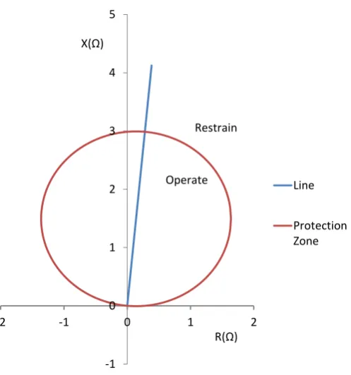
Figure 2-3 Mho distance protection characteristic
The area inside the characteristic is the operate region. The protected transmission line is inclined at its angle (e.g. 85° for a 400kV system with a 12 X/R ratio). Polarisation using healthy phase voltages is not possible during a three phase fault. Therefore, memory polarisation is used to overcome this. In this case, recent measurements of the faulty phase that are stored in the relay memory prior to fault inception are used. For non-symmetrical faults, healthy phases not affected by the fault can be used for polarisation which is known as cross polarisation [8].
Quadrilateral characteristics are mainly used to address the under-reach problem caused by resistive earth faults or arcing faults [17]. The resistive reach of the characteristic can be adjusted independently of the reactive reach as shown in Figure 2-4.
-1 0 1 2 3 4 5
-2 -1 0 1 2
Line
Protection Zone X(Ω)
Restrain
Operate
Figure 2-4 Quadrilateral characteristic showing independently adjustable resistive and reactive reaches
Plain (non-communications based) distance protection schemes are usually arranged in a stepped zone configuration (see Figure 2-5) to achieve remote backup functionality and, at the same time, coordinate with other distance schemes upstream of the relay. Each relaying point will usually have three active distance protection zones – zone 1, zone 2 and zone 3 (Z1–Z3). Each zone protects a predetermined circuit length and an appropriate time delay (e.g. t1 and t2) to coordinate between the different zones. Typical zone settings are summarised in Table 2-1 [8]. Zone 3 can be offset by 20% of the protected line length in order to provide backup protection for the local busbar.
Figure 2-5 Distance protection zones
R(Ω) X(Ω)
Z1
Z2 Line
Z1
Z1
Z2 Z3
R1
R2
Z2
Z3
t1 t2
Table 2-1 Typical distance protection zone settings [8]
Distance Zone Settings
Zone 1 80% of line impedance, instantaneous
Zone 2 100% of line impedance + 50% of shortest adjacent line, 0.5s delay
Zone 3 120% of line impedance and longest adjacent line, 1s time delay 20% of line impedance reverse reach
Zone 2 is set such that it coordinates with the shortest adjacent line. If this is not taken into account then selective operation can be lost as shown in Figure 2-6. If Z2 of R1 is set such that it covers 50% of the longest adjacent line (dotted line in Figure 2-6), then it would overlap with Z2 of R2 resulting in loss of coordination. As such, Z2 for R1 may trip before Z2 of R2 for a fault between R4 and the end of Z1 of R2 (fault position shown in Figure 2-6). Therefore, the dashed line represents the correct coordinated zone setup.
Figure 2-6 Zone 2 coordination with shortest adjacent line
2.3.2 Ground fault detection
Distance protection settings are expressed using positive sequence quantities. Apparent impedance is also calculated in the same manner. Therefore, to accommodate ground faults, a compensation factor is used in the calculation. This takes into account the ground loop impedance during a ground fault
R1
R2 R4
R3
Z1
Z2
Z1
Z2
Z2 Z1
Z1
Z2
different ways. Therefore, it is important to refer to the relay documentation to ensure the correct settings of the factor. for instance is normally calculated using the positive and zero sequence line impedances and respectively as in (3) [16]:
( ⁄ ) (3)
Alternatively, a residual compensation factor can be used where ⁄ . In this case, the measured ground fault impedance will depend on the residual current measurement instead of the zero sequence current used in (1) [16].
2.3.3 Communications based distance schemes
[image:42.595.108.519.434.649.2]The performance of distance protection schemes can be enhanced using communications channels. This is particularly useful in interconnected transmission circuits where faults at certain positions are not immediately cleared by zone 1 elements on both ends. Faster fault clearance times can be achieved through remote signalling. Two commonly used distance schemes are summarised in Table 2-2.
Table 2-2 Common communications based distance schemes and their application [8]
Scheme category Scheme types Principle of operation
Transfer tripping
Direct under-reach transfer trip, permissive under-reach transfer trip, permissive over reach transfer trip.
An intertripping signal from the fault detecting end of the line is used to directly trip the remote end of the line to accelerate fault clearance. Additional checks can be applied including remote zone 2 pickup and directional checks.
Overreach blocking
Over reach blocking using zone 1, over reach blocking using zone 2.
2.3.4 Distance protection application issues and considerations
Although distance protection is considered a mature protection method, a number of application challenges persist. These are briefly discussed here along with some advances aiming to tackle them.
a) Load encroachment
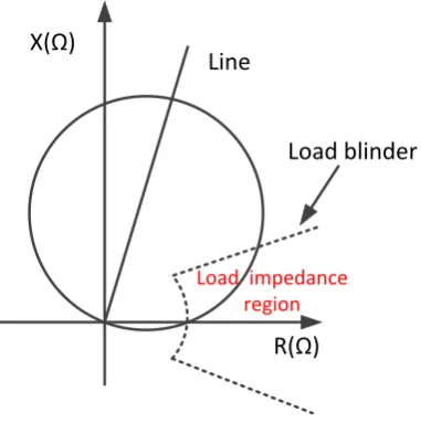
[image:43.595.224.415.357.549.2]Load encroachment occurs when the apparent impedance caused by a circuit overload encroaches into the distance protection zones. This usually occurs with long transmission lines whose impedance is comparable to that of the load and is usually accompanied with a voltage depression. Load encroachment into zone 3 was one of the main events leading to the North American blackout in 2003 [18]. Load blinders are usually used to deal with load encroachment. These eliminate the area of the distance characteristic prone to load encroachment as shown in Figure 2-7.
Figure 2-7 Load blinders used to minimise load encroachment
In a piece of work commissioned by NERC [19], it was concluded that if load blinders are used, transmission line loadability can be increased to 150% of the thermal rating while still providing adequate resistive fault coverage.
R(Ω) X(Ω)
Line
Load blinder
b) Multi terminal line arrangements
Distance schemes applied to multi-terminal circuit configurations (as shown in Figure 2-8) are particularly challenging [20]. Different source infeeds from the circuit terminals affect the apparent impedance seen by the relay which may cause reach inaccuracies. For example, the fault contribution from the teed circuit for the fault illustrated in Figure 2-8 results in an increase in the apparent impedance measured at R1. Zone 2 set to protect the remote busbar B and beyond would then under-reach [8]. The reach of Zone 2 for R1 can be set to take into account the worst case infeed from the teed feeder. This may result in a large overreach when the infeed is switched off. An under-reach direct transfer trip scheme may also be used [8].
Figure 2-8 Distance protection of multi-terminal circuits
c) Mutual coupling between parallel circuits
Zero sequence mutual coupling between parallel lines during earth faults can result in under-reach [3, 21]. This is particularly problematic with un-transposed lines. This can usually be addressed using additional current inputs from parallel circuits into the distance scheme to compensate for the coupling effect. Additional factors can affect the reach accuracy including earthing arrangements and the earthing or otherwise of de-energised parallel lines. Another compensation technique proposed in literature determines the state of the circuits involved and produces a correction factor accordingly [22].
R1 Set Z2 Seen Z2
A
B
d) Circuits with Flexible AC Transmission Systems (FACTS)
The connection of FACTS devices (e.g. series and shunt compensation) present a number of challenges, mostly reach related, when setting distance protection relays [23-25]. Transmission system operators usually deal with such problems on a case by case basis with through detailed system studies and manufacturer recommended settings [20]. Some of these issues will be picked up in chapter 3
2.4 DER interface protection
Engineering recommendations such as G59/2 [26] in the UK or IEEE 1547 guidelines [27] stipulate the functions necessary to protect the DER. These differ according to the type of DER, the voltage level it is connected to and the country. [28] provides useful information on international practices related to the protection of DER. This section focuses on loss of mains (LOM) protection functions as it will be revisited in chapter 3.
2.4.1 Loss of mains protection
Loss of mains is the condition where a section of the distribution network is disconnected from the main grid and remains energised by installed DER. This islanded mode of operation is not currently permitted due to the following reasons [29]:
The islanded distribution network frequency may drift in relation to the main grid. Therefore, out of synch re-closures at the point of common coupling are a possibility unless check synchronism functionality is fitted.
Power quality usually cannot be maintained by DER.
Operational procedures normally assume that an islanded network is not energised which if it were not true would pose a safety risk to personnel working on this network.
loading are closely matched then it is more difficult to detect the islanding event. Therefore, more specialised protection functions are included. The most commonly used functions are rate of change of frequency (ROCOF) and voltage vector shift (VS) [8].
ROCOF as the name suggests monitors variation in system frequency as an indicator for LOM. The rate of change of frequency ⁄ can be calculated according to (4) over a three cycle window using measured frequency [30]:
⁄
(4)
ROCOF can suffer from spurious tripping in response to remote disturbances. Such behaviour can lead to undesirable tripping of DER which can exacerbate system frequency disturbances [31]. A number of alternative solutions have been proposed to improve the stability of ROCOF such as CO-ROCOF which relies on communications to enhance the scheme performance [32]. Other communications-based protection algorithms in the research stage rely on internet [33] or satellite [34] communications to provide a reference frequency signal representing the frequency of the grid.
Recent developments, that are undergoing field trials, include the phase angle drift (PAD) algorithm. This LOM protection algorithm relies on historical frequency data and an accumulator which, when it exceeds a pre-set threshold, results in a trip command [35].
2.5 System integrity protection schemes
excursions in voltage limits (usually voltage depression) should be treated to avoid a system voltage collapse. This can be remedied by managing power flows or switching of FACTS [37]. The advent of wide area measurements promises more flexibility in available protection actions through the implementation of more advanced SIPS functions.
2.6 Wide area measurement, protection, automation and control
2.6.1 Synchrophasor measurement technology
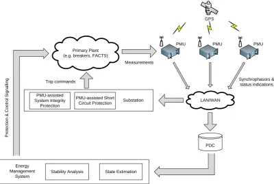
Collecting synchronised voltage measurements from remote busses was first discussed in [11]. The technology has since then developed significantly and currently relies on GPS (global positioning system) as a universal source of synchronising signals. These signals are used by phasor measurement units (PMU) to time stamp each measurement made for comparison at a later stage. The operation of PMUs is described in standard IEEE C37.118 [38, 39]. Synchrophasor measurement technology (SMT) consists of a number of building blocks which provide data measurement, collection, archiving and visualisation systems. SMT can be used in a range of applications, mainly in system monitoring where it is usually referred to as a wide area measurement system (WAMS) [40].
Figure 2-9 Typical WAMPAC architecture
2.6.2 Protection applications of SMT
SMT is seen as an enabler for more advanced system integrity protection functions. The ability to compare measurement from the wider network can enable greater flexibility and potentially more selective protection operation. Below is a list of some SMT based protection functions proposed in the literature [42]:
Predictive angular and voltage stability protection.
Fault localisation and classification.
Precise islanding detection.
Adaptive load shedding.
Real-time state measurement or estimation to enable further protection and control functions.
It is envisaged that SMT technology can enhance dependable and secure performance of SIPS. By shifting the balance between these performance criteria when the system is normally loaded or under stress respectively, undesirable operation can be avoided [43].
GPS
PMU PMU PMU
LAN/WAN
PDC
Stability Analysis State Estimation Energy
Management System
PMU-assisted Short
Circuit Protection Substation Primary Plant
(e.g. breakers, FACTS)
Synchrophasors & status indications P ro te c ti o n & C o n tr o l S ig n a lli n
g Trip commands
Measurements
PMU-assisted System Integrity
2.7 The digital substation
The introduction of microprocessor based protection and control devices has enabled the delivery of more powerful and flexible functions. The term digital substation refers to the integration of these devices over communications channels. Intelligent electronic devices (IEDs) are considered the building block of digital substations.
2.7.1 Intelligent electronic devices
Relaying platforms have evolved from electromechanical based protection relays to multifunctional numerical functions implemented on IEDs. The latter offers a wide range of protection functionality within a single physical device along with more integration of monitoring and control functions.
2.7.1.1 IED advantages over legacy relaying platforms
Greater flexibility in protection scheme deployment is achieved due to a potentially large number of protection and automation functions that can be activated on any given IED. IEDs are based on embedded platforms that constitute modular hardware components. This means that upgrading a scheme’s I/O or hardware capabilities is a relatively straightforward task since complete hardware replacement is not necessary. Upgrades to the functionality can also be achieved through firmware upgrades. Figure 2-10 shows a typical hardware architecture of a modern IED [8, 10].
Figure 2-10 IED hardware architecture
CPU
Communication module
Volatile Memory Flash Memory ADC
Input Isolation Input filters Optical inputs
Output relays
HMI
Protection
signalling Trip commands Analogues
The use of a numerical platform allows the use of advanced measurement techniques including adaptive digital filtering and adaptive frequency tracking. Consequently, protection algorithms can be more immune to adverse conditions such as harmonics. Furthermore, reliable operation can be maintained even at off nominal system frequencies [44]. Digital fault and event recording are standard features in protection IEDs. These enable the performance of post fault diagnostics to verify relay operation. IED now also integrate PMU measurement capabilities, a testament of a highly integrated and powerful substation automation platform.
The ability to communicate remotely with IEDs is perhaps one of the most compelling benefits of the platform. Not only does this allow the remote interrogation of the relay status including the extraction of fault records, but it also allows remote configuration of the relay including the adjustment of its settings.
Figure 2-11 Typical PSL diagram [45]
2.7.1.2 IED reliability
IEDs have built in features that enhance their reliability. For instance, the overall health of the hardware and software execution is monitored using watchdog functions and checksums [8]. These self-supervision features allow early detection of IED or auxiliary system faults by raising appropriate alarms. As a result, the mean time to repair (MTTR) is significantly reduced compared to standard maintenance cycles (1-5 years). Consequently, higher relay availability is achieved [46]. I/O supervision including current transformer (CT), voltage transformer (VT) and trip circuit supervision are also standard features of IEDs. Faults in any of these components can be identified and reported.
IEDs also employ security measures such as multi-level password protection to prevent unauthorised access to the devices and unapproved changes in their configuration. These are important cyber security features as modern substations become increasingly accessible remotely and reliant on mainstream ICT technologies.
2.7.2 IEC 61850 communications standard
Proprietary communications protocols are very common among protection devices. This impeded further integration between devices from different manufacturers. Greater interoperability was desired by utilities such that scheme replacement costs are minimised and its process simplified. The IEC 61850 is a standard for communications networks and systems in substations [47]. It aims to enable interoperability between devices from different manufacturers by specifying a data model and a mapping between the model and the underlying mainstream communications stack to perform required data exchange services.
IEC 61850 emphasises functional abstraction by utilising the so called logical nodes (LN). Substation automation functions are decomposed into LNs which reside in physical devices (PD). LNs are effectively containers of data objects (DO) which can be exchanged between devices from different vendors. This hierarchy is illustrated in Figure 2-12.
Figure 2-12 IEC 61850 functional hierarchy
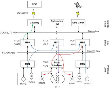
A typical substation architecture employing IEC 61850 is depicted in Figure 2-13. The process bus is where measurement and control commands are exchanged in a digital format. Analogue measurements are digitised using merging units (MU) or NCITs and are transferred across the process bus at a high rate using sampled values (SV), the format of which is specified in the standard. This allows the sharing of measurements between different devices without the need for dedicated hardwiring between transducers and relays.
Physical device (network address) Logical device (IED)
Logical Node (XCBR) Logical Node (PDIS) DO (Pos) DO (Loc)
Attributes: - stVal - q ...
Attributes: - stVal - t ...
DO (Op) DO (Ofs) Attributes:
- phsA - neut ...
Attributes: - units - setMag ...
This provides significant cost savings in wiring. Measurement circuit redundancy can still be achieved by configuring the process bus in a ring arrangement. Tripping signals are exchanged using high speed GOOSE (generic object oriented substation event) messages. The station bus interconnects the protection and control bays with substation gateways and human machine interfaces (HMI). The nature of the communications at the station bus means they are not as time critical as those at the process bus and follows a client-server approach. Data related to fault records and alarms are transferred across the station bus.
Figure 2-13 Typical substation architecture utilising IEC 61850
The level of interoperability achieved can only be as robust as the tools used to configure the substation automation system. An XML based substation configuration language (SCL) is specified in the standard. Engineering tools from different vendors can produce and make use of files to configure protection devices from different manufacturers. The files used contain
MU1 Plant
Interface MU2
IED1 IED2 IED3
Gateway GPS Clock
![Table 2-2 Common communications based distance schemes and their application [8]](https://thumb-us.123doks.com/thumbv2/123dok_us/1655229.119083/42.595.108.519.434.649/table-common-communications-based-distance-schemes-application.webp)
![Figure 2-11 Typical PSL diagram [45]](https://thumb-us.123doks.com/thumbv2/123dok_us/1655229.119083/51.595.158.470.55.304/figure-typical-psl-diagram.webp)
![Figure 3-3 QB substation connection arrangement [33]](https://thumb-us.123doks.com/thumbv2/123dok_us/1655229.119083/72.595.151.482.58.293/figure-qb-substation-connection-arrangement.webp)
![Figure 3-5 Typical QB local control system [33]](https://thumb-us.123doks.com/thumbv2/123dok_us/1655229.119083/73.595.181.454.57.276/figure-typical-qb-local-control-system.webp)