Dadzie, Kokou and Dongari, Nishanth (2012) Transition regime analytical
solution to gas mass flow rate in a rectangular micro channel. In: 28th
International Symposium on Rarefied Gas Dynamics, 07-09 -
2012-07-13. ,
This version is available at
https://strathprints.strath.ac.uk/40484/
Strathprints is designed to allow users to access the research output of the University of Strathclyde. Unless otherwise explicitly stated on the manuscript, Copyright © and Moral Rights for the papers on this site are retained by the individual authors and/or other copyright owners. Please check the manuscript for details of any other licences that may have been applied. You may not engage in further distribution of the material for any profitmaking activities or any commercial gain. You may freely distribute both the url (https://strathprints.strath.ac.uk/) and the content of this paper for research or private study, educational, or not-for-profit purposes without prior permission or charge.
Any correspondence concerning this service should be sent to the Strathprints administrator: [email protected]
The Strathprints institutional repository (https://strathprints.strath.ac.uk) is a digital archive of University of Strathclyde research outputs. It has been developed to disseminate open access research outputs, expose data about those outputs, and enable the
Transition Regime Analytical Solution to Gas Mass Flow
Rate in a Rectangular Micro Channel
S Kokou Dadzie
∗and Nishanth Dongari
†∗Mechanical and Aeronautical Engineering, Glynd ˆwr University, Mold Road, Wrexham LL11 2AW, UK †Department of Mechanical and Aerospace Engineering, University of Strathclyde, Glasgow G1 1XJ, UK
Abstract. We present an analytical model predicting the experimentally observed gas mass flow rate in rectangular micro channels over slip and transition regimes without the use of any fitting parameter. Previously, Sone reported a class of pure continuum regime flows that requires terms of Burnett order in constitutive equations of shear stress to be predicted appropriately. The corrective terms to the conventional Navier-Stokes equation were named the ghost effect. We demonstrate in this paper similarity between Sone ghost effect model and newly so-called ‘volume diffusion hydrodynamic model’. A generic analytical solution to gas mass flow rate in a rectangular micro channel is then obtained. It is shown that the volume diffusion hydrodynamics allows to accurately predict the gas mass flow rate up to Knudsen number of 5. This can be achieved without necessitating the use of adjustable parameters in boundary conditions or parametric scaling laws for constitutive relations. The present model predicts the non-linear variation of pressure profile along the axial direction and also captures the change in curvature with increase in rarefaction.
Keywords: mass diffusion; volume diffusion hydrodynamics; microchannel gas flow; Knudsen paradox; pressure distribution; slip flows
PACS: 47.61.-k, 47.61.Cb, 47.61.Fg
INTRODUCTION
Growing demands in microdevice technology involving the motion of fluids at micro- and nano-length scales open a new branch in fluid mechanics requiring investigation of fluid flows occurring exclusively in ultra-small devices. Examples of these mechanical systems include micro-pumps, heat exchangers, jet polishing/cutting systems and, more importantly, the entire range of Micro-Electro-Mechanical Systems (MEMS) encompassing their various bio-engineering applications [1, 2, 3].
Knudsen [4] experimental study, was among the first designed to report data pointing to anomalous behaviour of rarefied gas flow through capillaries. Many experiments have since confirmed Knudsen’s initial observations [5, 6, 7]. Meanwhile, it is now widely accepted that the standard set of fluid mechanical equations, namely those due to Navier-Stokes-Fourier, are inapplicable. Among recent developments in predicting these phenomena, Gallis and Torczynski [8] have presented a direct Monte Carlo simulation (DSMC). Gorji et al. [9] obtained the mass flowrate by solving, numerically, a velocity-space stochastic equation addressing molecular motions. Veltzke and Thaming [10] pointed out that the mass flowrate in the slip flow regime can be accurately predicted by arguments of molecular spatial diffusion effects without using any fitting parameter.
A CONSISTENT VOLUME DIFFUSION HYDRODYNAMIC MODEL: SONE GHOST
EFFECT
Appearing in the following equations is the material derivative defined asD/Dt=∂/∂t+Um·∇, wheretis the time variable andUm represents mass-based average velocity: that is a flow macroscopic velocity as seen in a conven-tional continuity equation. A volume diffusion hydrodynamic model consistent with mechanical and thermodynamic principles is written [12]:
Dρ
Dt =−ρ∇·Um, (1)
ρDUm
Dt =−∇·Π, (2)
ρD Dt
1 2U
2
m+ein
=−∇·[Π·Uv]−∇·Ju, (3)
that is closed with
Π=pI−2µ∇U˚v, Uv=Um+Jv, (4)
where
Jv=
κm
ρ ∇ρ, Ju=−κh∇T, (5)
and
˚
∇Uv=
1 2
∇Uv+∇Uv
−1
3∇·UvI. (6)
The single bar over the velocity gradient in this last equation denotes the transpose operator, withIthe idemfactor. In the above set of equations (1) to (5):ρ is the mass density,pthe pressure,T the temperature, andeinthe fluid’s mass-specific internal energy density, the latter related to the temperature byein= (3/2)RT,withRthe specific gas constant. VelocityUvappearing in expression of the shear stress is the volume velocity: that is a macroscopic velocity based on averaging method that accounts for the fluid molecular spatial distributions and not only their masses. ThereforeJv is a volume diffusion flux that appears as we distinguish volume averaging from mass or gravimetric averaging [13]. Presence of fluxJvin the shear stress makes the above hydrodynamic model of Burnett level. Indeed, using the ideal gas law written in the form
∇p
p =
∇ρ
ρ +
∇T
T , (7)
volume diffusion momentum equation (2) becomes
ρDUm Dt =−∇·
pI−2µ∇U˚m+2µκm ˚
∇∇lnT
, (8)
if local relative pressure variations are neglected. In equation (8), we observe that the third term involving temperature gradients on the right-hand-side, is a thermal stress term that is obtained traditionally at the second order in Chapman-Enskog expansion; so it is a Burnett shear stress term. This term is identical to corrective terms to the Navier-Stokes equation called “ghost effect terms”: conveying that this is a higher order Knudsen number term, which is found to influence flows in the pure hydrodynamics or pure continuum regime. Derivation of volume diffusion hydrodynamic set (1) to (5), does not involve any small parameter expansion procedure. Consequently, within this set of equations, the volume diffusion presumably may have influence at any Knudsen number order; a situation that appears to corroborate with Sone ghost effects.
ANALYTICAL SOLUTION
We consider a steady-state isothermal pressure-driven flow occurring in a rectangular microchannel. The streamwise flow coordinate variable is denotedxand the wall normal coordinate is denotedy. The height and width of the channel are denoted respectively byh andw, whereinw>>h such that the flow may be supposed two-dimensional. The rectangular channel height-to-length ratioh/Lis assumed to be small to neglect the inlet and outlet effects. Velocity component,Um=Um(x,y)is restricted to the streamwise direction and is a function ofxandy. Disregarding energy equation, continuity and volume diffusion momentum equations (1) and (2) can be written as :
∇·[ρUm] =0, (9)
∇·[ρUmUm] =−∇p−∇·Πv. (10)
In terms of boundary conditions, impenetrability of mass at the channel walls requires normal component of mass velocityUmto vanish aty=±h/2. In addition, we impose on the volume velocity a form of slip condition so that all boundary conditions are written:
umy(x,±h/2) =0, (11)
and
uvx(x,±h/2) =Jvx(x,±h/2) =∓λoρo
1 ρ ∂u vx ∂y
y=h/2
=∓λoρo 1 ρ ∂u mx ∂y
y=h/2
, (12)
In boundary conditions (11) and (12), subscriptxandyrefer to components inxandydirections, respectively. Subscript ‘o’, refers to the channel outlet, which is simply used here as a convenient arbitrary reference. Furthermore,λois the gas mean free path at the channel outlet. Note that equation (12) is not a standard slip condition, as the equation can be viewed as a constitutive equation for the volume fluxJvat the boundary whenumx=0 (i.e., when the no-slip boundary
condition is imposed on the mass velocity).
A solution method starts with continuity and momentum equations (9) and (10), reformulated as:
ρ∂umx
∂y + ∂
∂x[ρuvx]−
k cp
d2lnρ
dx2 =0, (13)
µ∂
2u
vx
∂y2 =
d p
dx. (14)
The solution of equation (14) satisfying boundary condition (12) is
uvx=
1 8µ
d p dx
4y2−h2−8µE1 ρ
, (15)
in which we denoteE=h2Kno/(2νo), whereinνodenotes the kinematic viscosity at the outlet, andKno=λo/his the outlet Knudsen number. Substituting (15) into (13) and solving the resulting expression forumx, by subjecting to the
boundary condition (11) results in
umx=−
1 8µ 4 3y 3
−h2y
1
ρ d dx
ρd p
dx
+Ey1 ρ
d2p dx2+y
k cpρ
d2lnρ
dx2 +C(x), (16)
where the integration constantC(x)is a function only ofx. However, application of boundary conditions (12) requires thatC(x) =0 as a result of symmetry. The preceding equations furnish the pressure distribution in accordance with the following scheme. Evaluate equation (16) aty=±h/2, and use boundary condition (12) to obtain
1 12h
2d
dx
ρd p
dx
+Ed
2p
dx2+
k cp
d2lnρ
dx2 =0. (17)
Eliminate the density in equation (17) in favour of the pressure via use of the ideal gas lawp=ρRT, and subsequently use the identitypd p/dx= (d/dx)(p2/2)to obtain
d dx2
p2+24µRT
h2
E p+ k
cp lnp
Integration of equation (18) followed by rearrangement yields
p
po
2
+F p po +G ln p po
+lnpo
=Cx
L+D, (19)
where
F=24µRT
h2p
o
Eand G=24µRT
h2p2
o
k cp
. (20)
Alternatively, in terms of the Knudsen and Prandtl numbers,
Kno=
kλ h
µ po
√
2RT, Pr=cpµ/k, F=12Kno, G= 24
Prk2λKn
2
o, (21)
wherekλ =p
π/2 is a coefficient associated with the definition of the mean free path as related to the choice of molecular collision model. Equation (19) is the pressure distribution, in which constantsCandDare determined from knowledge of the channel inlet and outlet pressures,p(x=0) =piandp(x=L) =po.This furnishes expressions
C=−
(P2−1) +F(P−1) +GlnP
, D=P2+FP+G(lnP+lnpo), (22)
whereP=pi/po, denotes the inlet/outlet pressure ratio. The mass flowrate through the channel is given by the formula
˙
M=w Z h/2
−h/2ρ
Umdy=const. (23)
UsingUm=Uv−Jv, with equations (15) and (5) we have that
umx=
1 8µ
d p dx
4y2−h2−8µE1 ρ
−ck
pρ
dlnρ
dx . (24)
Multiply equation (24) byρ and subsequently eliminateρ in favor ofp on the right-hand side. Introduction of the resulting expression into equation (23) yields
˙
M=− wh
3
24µRT d dx
p2+24µRT
h2
E p+ k
cp lnp
. (25)
The bracketed term in equation (25) is seen to be identical to the bracketed term in equation (18). It follows that
˙
M=− wh
3p2
o
24LµRTC, (26)
whereCis the constant given by equation (22). Thus, the mass flow rate is given explicitly in terms of the parameters characterizing the problem as
˙
M= wh
3p2 0
24LµRT "
(P2−1) +12Kno(P−1) + 24
Prk2
λ
Kn2olnP #
. (27)
Equation (27) has a structure frequently obtained when slip boundary conditions are used [17]. However, our goal in this investigation is to demonstrate that, due to the use of volume diffusive flux, equation (27) can reproduced faithfully the experimental data without the use of any fitting parameter.
Indeed, in the course of gas-kinetic molecular description of the hydrodynamic set of equations (1)-(5), volume diffusion is a manifestation of the molecular-level spatial diffusion process that used to be ignored [18]. This, in turn, generates a second level of non-equilibrium scaling beyond, or parallel to, traditional Knudsen number scaling [12]. Veltzke and Thaming [10] demonstrated in this context that volume diffusivity coefficient depends not only on the properties of the gas but also on the channel geometry. This leads us to identify a volume diffusivity coefficient for the rectangular channel corrected by the channel dimensions as,κ∗
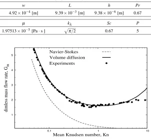
TABLE 1. Summary of fluid properties and physical coefficients used in figure 1
w L h Pr
4.92×10⁻⁴[m] 9.39
×10−3[m] 9.38
×10−6[m] 0.67
µ kλ Sc P
1.97513×10⁻⁵[Pa·s ] p
π/2 0.67 5
1 2 3 4 5
0.1 1 10
dimless mass flow rate, G
m
Mean Knudsen number, Kn Navier-Stokes
Volume diffusion Experiments
FIGURE 1. Mass flow rate as predicted by volume diffusion hydrodynamics compared with experimental data
by a factorL/win the final pressure distribution equation (19), and the mass flow rate equation (27). Full expression of the micro gas mass flow rate in rectangular channel using the volume diffusion momentum equation is therefore finally given by
˙
M= wh
3p2 0
24LµRT "
(P2−1) +12Kno(P−1) + 24w PrLk2λKn
2
olnP
#
, (28)
in which, there appear only physical properties with no coefficient playing a fitting role such as a slip coefficient. These physical properties in the case of Ewart et al. [7] experimental data for gaseous helium are summarized in table 1. A full comparison between predictions by equation (28) and experiments are seen in figure 1, plotted in the form of dimensionless flowrate,Gm, vs the mean Knudsen number that are defined by
Kn[mean] =kλ
h µ
pi+p0
2
√
2RT, Gm=M˙∗
wh2
L√2RT(pin−pout)
−1
. (29)
From the figure, the volume diffusion model, i.e. equation (28), agrees with experimental data up to a Knudsen number of about 5 with all parameters possessing clear physical meanings as given in table 1 and a viscosity coefficient having its appropriate experimental value. This agreement can be said an excellent achievement considering the fact that conventional Navier-Stokes modified by slip boundary corrections, gives agreement with the data within the slip but not deep into the transition regime as the present volume diffusion model does.
0 0.2 0.4 0.6 0.8 1 1
2 3
x/L
p(x)/p
out
P = 2.70
P = 2.36
[image:7.595.162.452.81.262.2]P = 2.02 Experimental Data
FIGURE 2. Pressure distribution as predicted by volume diffusion model compared with experimental data of Pong et al. [19] for an outlet Knudsen number of 0.044 and various pressure ratios (P).
(a)
0 0.2 0.4 0.6 0.8 1
1 1.5 2 2.5 3
x/L
p(x)/p
out
Kn = 0.01 Kn = 0.1 Kn = 0.5 Kn = 2
(b)
0 0.2 0.4 0.6 0.8 1
−0.1 −0.05 0 0.05 0.1 0.15
x/L
[ p − p
lin
]/[ p
in
− p
out
]
Kn = 0.01 Kn = 0.1 Kn = 0.5 Kn = 2
FIGURE 3. (a) Normalized pressure distribution along the streamwise direction for various Knudsen numbers, (b) dimensionless deviation of the pressure distribution from the linear pressure distribution as a function of the dimensionless distance.
[image:7.595.83.534.311.487.2]CONCLUSION
In this paper we derived an analytical solution to Knudsen enhanced mass flowrate phenomena in micro gas channels using a volume diffusion hydrodynamic model. The solution equation is similar in form to that obtained using first and second order slip boundary conditions. However, with the volume diffusion approach and volume diffusivity coefficient that depends on the geometry of the channel, we obtain agreement with the experimental data up to Knudsen number of 5. It also allows the direct investigation of the non-linear pressure distribution, and predicts the change in curvature of the streamwise pressure profile with an increase in rarefaction (when the diffusive effects dominate the convective fluxes).
ACKNOWLEDGMENTS
ND would like to thank the European Community’s Seventh Framework Programme FP7/2007-2013 under grant agreement ITN GASMEMS no215504.
REFERENCES
1. G. Karniadakis, A. Beskok, and N. R. Aluru,Microflows and Manoflows: Fundamentals and simulations, Springer, 2005. 2. S. Colin,Microfluidics, ISTE, 2010.
3. G. Kandlikar, S. Garimella, D. Li, S. Colin, and M. R. King,Heat transfer and fluid flow in minichannels and microchannels, Elsevier, 2006.
4. M. Knudsen,Ann. Phys-Leipzig28, 75 – 130 (1909).
5. E. B. Arkilic, K. S. Breuer, and M. A. Schmidt,J. Fluid Mech.437, 29–43 (2001). 6. J. Maurer, P. Tabeling, P. Joseph, and H. Willaime,Phys. Fluids15, 2613 (2003). 7. T. Ewart, P. Perrier, I. Graur, and J. M. Meolans,J. Fluid Mech.584, 337 – 356 (2007). 8. M. A. Gallis, and J. R. Torczynski,Phys. Fluids24, 012005 (2012).
9. M. H. Gorji, M. Torrilhon, and P. Jenny,J. Fluid Mech.680, 574–601 (2011). 10. T. Veltzke, and J. Thaming,J. Fluid Mech.698, 406–422 (2012).
11. Y. Sone,Annu. Rev. Fluid Mech.32, 779–811 (2000).
12. S. K. Dadzie, and J. M. Reese,Phys. Rev. E85, 041202 (2012). 13. S. K. Dadzie, and J. M. Reese,Phys. Fluids22, 016103 (2010). 14. L. García-Colin, R. Velasco, F. Uribe,Phys. Rep.465, 149–189 (2008). 15. H. Brenner,Int. J. Eng. Sci.47, 930–958 (2009).
16. H. Brenner,Physica A349, 11–59 (2005).
17. I. A. Graur, J. G. Meolans, and D. E. Zeitoun,Microfluid Nanofluid2, 64–77 (2006). 18. S. K. Dadzie, J. M. Reese, and C. R. McInnes,Physica A387, 6079–6094 (2008).
19. K. Pong, C. M. Ho, J. Liu, Y. C. Tai,Proceedings of Application of Microfabrication to Fluid Mechanics, ASME Winter Annual Meeting, Chicago, 51-56 (1994).