UNIVERSITI TEKNIKAL MALAYSIA MELAKA (UTeM)
Engine RPM Based Sensing Techniques
Thesis submitted in accordance with the partial requirements of the
Universiti Teknikal Malaysia Melaka for the
Bachelor of Manufacturing Engineering (Hons)(Robotics and Automation)
By
Hairol Farisah Jaafar
ENGINE RPM BASED
SENSING TECHNIQUES
HAIROL FARISAH B. JAAFAR
UTeM Library (Pind.1/2007)
UNIVERSITI TEKNIKAL MALAYSIA MELAKA
BORANG PENGESAHAN STATUS TESIS*
JUDUL: _______________________________________________________________ _______________________________________________________________ _______________________________________________________________ SESI PENGAJIAN : _______________________
Saya _____________________________________________________________________
mengaku membenarkan tesis (PSM/Sarjana/Doktor Falsafah) ini disimpan di Perpustakaan Universiti Teknikal Malaysia Melaka (UTeM) dengan syarat-syarat kegunaan seperti berikut:
1. Tesis adalah hak milik Universiti Teknikal Malaysia Melaka .
2. Perpustakaan Universiti Teknikal Malaysia Melaka dibenarkan membuat salinan untuk tujuan pengajian sahaja.
3. Perpustakaan dibenarkan membuat salinan tesis ini sebagai bahan pertukaran antara institusi pengajian tinggi.
4. **Sila tandakan (√)
(HURUF BESAR)
SULIT
TERHAD
TIDAK TERHAD
(Mengandungi maklumat yang berdarjah keselamatan atau kepentingan Malaysia yang termaktub di dalam AKTA RAHSIA RASMI 1972)
(Mengandungi maklumat TERHAD yang telah ditentukan oleh organisasi/badan di mana penyelidikan dijalankan)
(TANDATANGAN PENULIS) Alamat Tetap: Tarikh: _______________________ Disahkan oleh: (TANDATANGAN PENYELIA) Cop Rasmi: Tarikh: _______________________
* Tesis dimaksudkan sebagai tesis bagi Ijazah Doktor Falsafah dan Sarjana secara penyelidikan, atau disertasi bagi pengajian secara kerja kursus dan penyelidikan, atau Laporan Projek Sarjana Muda (PSM). ** Jika tesis ini SULIT atau TERHAD, sila lampirkan surat daripada pihak berkuasa/organisasi berkenaan dengan menyatakan sekali sebab dan tempoh tesis ini perlu dikelaskan sebagai SULIT atau TERHAD.
Engine RPM Based Sensing Technique
2007/2008
HAIROL FARISAH BIN JAAFAR
√
DECLARATION
I hereby, declared this project entitled “Engine RPM Based Sensing Technique” is the results of my own research except as cited in references.
Signature : ……….
Author’s Name : ………
Date : ………
APPROVAL
This report submitted to the Senate of UTeM and has been accepted as partial
fulfillment of the requirements for the degree of Bachelor of Manufacturing Engineering
(Robotics and Automation). The member of the supervisory committee is as follow:
……….
Project Supervisor
ABSTRACT
This research is intended to find about how to derive an output signal (electrical) from a
rotating body. The objective is to design a system that can detect the rotating body
revolution per minute (rpm) value. The system must also have the capability to produce
output(s) at certain triggering point(s) which is operator-defined. The signal produce
from the system can be manipulated to trigger other system or device. In designing the
system, flexibility will be taken into account so that if the system works, it can be
implemented not only on vehicle’s engine system but also in any rotating/ reciprocating
body. Other design considerations are accuracy, repeatability, rigidity, simplicity,
reliability and cost. Complex system will try to be avoided if possible to ease tuning and
troubleshooting. This project is highly significance in the automation industry as
motorized device is a must in this industry and such system is still lacking. This system
can be implemented in automation for example as a switch for other subsystem, speed
ABSTRAK
Matlamat kajian ini dijalankan adalah untuk menerbitkan signal keluaran (dalam bentuk
elektrik) berdasarkan putaran sesuatu jasad atau objek. Objektif kajian adalah untuk
mengembangkan sebuah sIstem yang mampu mengesan kelajuan (ppm-putaran per
minit) putaran sesebuah jasad. Sistem juga harus mampu menerbitkan signal keluaran
pada nilai-nilai kelajuan ppm yang tertentu mengikut kemahuan pengoperasi. Signal
keluaran tersebut boleh digunakan untuk mengaktifkan sistem atau alat yang lain. Semasa
mengembangkan sistem ini, fleksibiliti sistem diambil kira agar sekiranya sistem ini
berjaya beroperasi, ia boleh diimplementasikan bukan sahaja ke atas sistem enjin
kenderaan bermotor tetapi juga kepada semua jasad berputar. Pertimbangan lain yang
diambil kira dalam pembinaan sistem termasuklah ketepatan, kejituan, ketahanan,
keringkasan sistem dan kos. Sistem yang kompleks cuba dihindari agar kerja-kerja
menyelaras dan membaiki mudah. Projek ini amat signifikan dalam bidang automasi
kerana ia banyak menggunakan motor. Sistem ini boleh diimplementasikan dalam
automasi contohnya sebagai suis kepada sub-sistem, pengawal kelajuan motor/ cahaya
DEDICATION
ACKNOWLEDGEMENTS
I would like to express my gratitude to all those who gave me the possibility to complete
this thesis. My special thanks goes to my beloved family, my father Jaafar Othman and
mother Siti Afsah Mohd Kudi who support me in good and bad times that without their
support I would not be able to finish this project. I am deeply indebted to my supervisor
Mr. Sivarao for always being there, encouraging and stimulating suggestions in spite of
his heavy work and teaching schedule. I also would to thanks my colleagues, Nur Nazatul
Nura Mohamed Fouzy and Mohamed Azraai Ahmad Puad for encouragement and
friendship and helping me immensely by hearing my ideas out loud and reflecting them
in suggestion which is vital in writing this thesis and doing this project. Thanks also go to
Mr. Chen from Mechatronics Sdn. Bhd. and Mr. Johnny from T.S. Electrical Sdn. Bhd.
for spending some time helping me sourcing parts and solution for my electrical parts
problems. For every other person whose names were too long to be listed here who have
helped in finishing this project directly or indirectly, I gave you all my gratitude. Last but
TABLE OF CONTENTS
Abstract ……… i
Abstrak ………. ii
Dedication ……… iii
Acknowledgements ……….. iv
Table Of Contents ……… v
List Of Figures ………. viii
List Of Tables ……….. x
List Of Abbreviations, Symbols, Specialized Nomenclature ……….. xi
List Of Appendices ……….. xii
1. INTRODUCTION ………... 1
1.1 Introduction ………... 1
1.2 Problem Statement ……… 1
1.3 Objective of the Research ………. 2
1.4 Scope ………. 3
1.5 Significant of Study ……….. 4
1.6 Conclusion ……… 4
2. LITERATURE REVIEW ………... 5
2.1 Introduction ………... 5
2.2 The System ………... 5
2.2.1 The Sensor ……….. 6
2.2.2 The Processing System (LM2907) ………. 7
2.2.3 The Output System ………. 9
2.3 Literature Review ………. 10
3. METHODOLOGY ……….. 15
3.1 Introduction ………... 15
3.2 Method Selection Chart ……….... 16
3.2.1 RPM Detection ………... 17
3.2.3 Sensor ………. 19
3.2.4 Processing System Design ……….. 20
3.2.5 Output System Design ……… 22
3.3 Full System Diagram ……… 24
3.3.1 8 volt Regulated Power Supply Circuit ……….. 25
3.3.2 5 volt Regulated Power Supply Circuit ……….. 26
3.3.3 Sensory Components ……….. 27
3.3.4 The Tachometer Circuit ……….. 28
3.3.5 L.E.D. Driver Circuit ……….. 29
3.3.6 Stepper Motor Circuit (output circuit) ……… 30
3.4 Conclusion ……… 32
4. RESULTS ………. 33
4.1 Introduction ………... 33
4.2 Result ……… 34
4.2.1 8 Volt Regulated Power Supply Circuit ………. 34
4.2.2 5 volt Regulated Power Supply Circuit ……….. 35
4.2.3 Sensory Components ……….. 36
4.2.4 The Tachometer Circuit ……….. 37
4.2.5 L.E.D. Driver Circuit ……….. 38
4.2.6 Stepper Motor Circuit (output circuit) ……… 39
4.3 Full System Test ………... 40
4.4 Conclusion ……… 42
5. CONCLUSION ……… 43
5.1 Introduction ………... 43
5.2 Discussion ………. 43
5.2.1 8 Volt Regulated Power Supply ………. 44
5.2.2 5 Volt Regulated Power Supply ………. 44
5.2.3 Sensory Components ……….. 45
5.2.4 The Tachometer Circuit ……….. 45
5.2.5 The L.E.D Driver Circuit ……… 48
5.2.6 The Stepper Motor Circuit ……….. 49
6. SUMMARY AND CONCLUSIONS ……….. 51
6.1 Introduction ………... 51
6.2 Summary of Project ……….. 52
6.3 Conclusion ……… 53
REFERENCES ……….. 54
APPENDICES ……… 55
A
Complete System Assembly
B
Hall-Effect Sensor
C
Motor Driving the Rotating Body
D
The Processing System
E
The Output System
F
PCB Drawing For the Processor System
LIST OF FIGURES
1.1 Gear, example of a rotating body
1.2 Expected linear correlation between engine rpm’s value and sensor’s output
1.3 Triggering points along the rpm range and the output signal
2.1 Tooth Ferromagnetic Wheel with known teeth, N
2.2 Sensor orientation
2.3 Variable Resistance pick-up sensor
2.4 LM2907 building block and pin numbering
2.5 LM2907 connection
2.6 Transistor system as used for switch
2.7 The sensing apparatus
2.8 Idealized plot for an engine rpm curve vs. the sensor output signal curve and
depicting the time relationship between two curves.
2.9 Flowchart for software algorithm used to determine engine position
3.1 Sample of a crankshaft
3.2 Hall-effect sensor sample image
3.3 Pin-outs of the LM2917
3.4 Sample of L.E.D. driven by LM3914
3.5 Full system diagram
3.6 8 volt regulated power supply circuit
3.7 5 volt regulated power supply circuit
3.8 Sensory component
3.9 The tachometer circuit
3.10 L.E.D. driver circuit
3.11 Stepper motor circuit
4.1 Testing 8 volt regulated power supply circuit
4.2 Testing 5 volt regulated power supply circuit
4.4 Oscilloscope output
4.5 Testing the tachometer circuit
4.6 Testing the L.E.D. driver circuit
4.7 Testing the stepper motor circuit
4.8 Complete system connected
5.1 Output of the hall-effect sensor sensing continuous rotation of the metal
gear
5.2 LM2917 pin outs
5.3 Location of R1,C1 and C2
5.4 LM3914 pin outs
LIST OF TABLES
3.1 Resistance value within a pair of wire
3.2 Output of stepper motor
3.3 Stepper motor wire sequence
4.1 8 volt regulator output with varying input voltage
4.2 5 volt regulator output with varying input voltage
4.3 Sensory circuit output
4.4 Result of tachometer circuit testing
4.5 L.E.D. output
4.6 Output of stepper motor
4.7 Output of the system
LIST OF ABBREVIATIONS, SYMBOLS, SPECIALIZED
NOMENCLATURE
AC - Alternate Current
DC - Direct CurrentAnalysis of Variance
EEM - Electronic Engine Management
I.C. - Integrated Circuit
L.E.D. - Light Emitting Diode
LCD - Liquid Crystal Display
PC - Personal Computer
PIC - Programmable Input Controller
PID - Proportional–Integral–Derivative
PLC - Programmable Logic Controller
PSM - Projek Sarjana Muda
RPM - Revolution per minute
TDC - Top Dead Centre
CHAPTER 1
INTRODUCTION
1.1 Introduction
Speed sensing has grown along with the automation industry since the 1970’s. Today
there are many type of speed sensing available whether it is a linear or angular
motion speed sensing. The sensors vary from contact mechanical type sensor using
linkage and gears, non-contact digital type sensors using magnetic system to optical
sensor. This broad selection provides solution to particular speed sensing problem
but not universally. For every moving or rotating body system, a unique system has
to be developed to monitor the speed. Some other system can be adapted to the
system while other cannot and new system has to be developed for them. For such
reason this study is conducted in hope that a more universal system can be design
and applicable to not only to sense engine rpm but other moving or rotating body as
well.
1.2 Problem Statements
The main concern in this study is how to derive output(s) from rpm value. Device
which can sense rpm value is readily available in today’s market. The problem arises
when a system needs a method to produce an output at certain point in the rpm range.
The reason to produce such method is to be as a speed control for example to prevent
a system from over/under running. A system which uses transition method for
example low volume pump switch to high volume pump at certain rpm will also be
2
1.3 Objective of the Research
In this study, the main objective is:
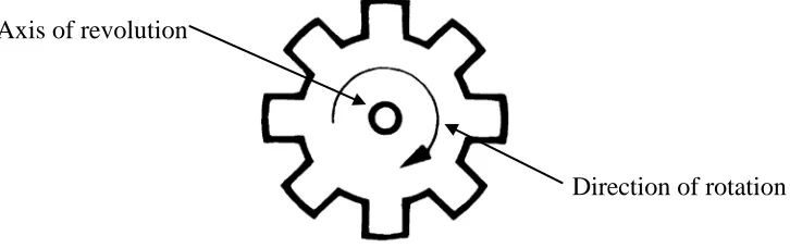
[image:18.595.129.492.199.313.2](a) To detect angular speed of a rotating body (engine crank).
Figure 1.1. Gear, example of a rotating body.
(b) To produce a readable output corresponding to the engine’s rpm.
- In the form of voltage or current reading
Figure 1.2. Expected linear correlation between engine rpm’s value and sensor’s
output
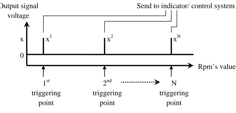
(c) To produce an output signal when the rpm value equals to the defined
triggering rpm point.
(d) To use the output as an input for indicator/ another control system. Axis of revolution
Direction of rotation
Voltage produced, V
[image:18.595.117.491.433.558.2]
Figure 1.3. Triggering points along the rpm range and the output signal
There are three basic needs that need to be fulfilled in achieving the above
objectives. The first thing is to determine a suitable existing output from the engine
to be the input to the system. The second thing is to select from the wide selection of
sensors available which type of sensing that will most suited the study. The third
thing is to determine what kind of system that will convert signal sense by the sensor
into a form of rpm value.
1.4 Scope
There are certain limitations and borders set to help in focusing in what is important
and needed in this project. The scope is set by considering the relevancy of the
components to this course and project.
The scope in this study will cover:
(a) Design of sensing system.
(b) Design of signal processing and output system from the sensor.
(c) Design of a prototype of the complete system.
(d) Fabricating and development of the system into working prototype.
x1 x2 xN
0 x Output signal voltage Rpm’s value 1st triggering point 2nd triggering point N triggering point
4
This study will not cover:
(a) Detail designing of the electronic system.
(b) Building circuit from scratch. Standard parts such as integrated circuit will be
used whereas possible as this is not an electronic project.
1.5 Significant of Study
Although a lot of manufacturer have already produced many type of rpm sensor
(tachometer), a universal type of rpm sensing system is still hard to find. There is still
less type of sensor that can be simply mounted on a rotating body and get the reading
instantly without much hassle. This system also can give many benefits to the
automation sector as there is a lot of area where speed control is needed and crucial.
The realization of this project can provide more opportunities in improving the
automation industries.
1.6 Conclusion
This project is challenging yet interesting to be done especially because it consists of
mechanical, electrical and electronic elements. Many hours of studying and complete
understanding of those elements involve are needed to make sure this project can be
CHAPTER 2
LITERATURE REVIEW
2.1 Introduction
Researches throughout the globe regarding this topic are not very easy to find.
However by searching through the sub component of the project it can be found. This
review gives a brief description about the level of development of sensing system
and signal processing nowadays. From the information based on the literature
reviewed, the tooth-wheeled variable reluctance sensing system is used as it suits this
project the most. The three basic parts which are the sensor, processing part and the
output part selected are explained below.
2.2 The System
The system is built based on a crankshaft position sensor system. The only
requirement needed for a system to be mounted with such system is that the rotating
[image:21.595.247.365.584.695.2]body to be measured must have toothed ferromagnetic wheel as in figure below:
6
[image:22.595.219.487.134.264.2]The sensor will be mounted in front of the rotating tooth as follows:
Figure 2.2. Sensor orientation
Ferromagnetic materials are material that is ferrous based (steel) and react to magnet.
The example is such as mild steel and stainless steel which is really easy to find
especially on a rotating shaft. The example of tooth ferromagnetic wheels can be
found on engine’s flywheel, gears and transmission and bike’s sprocket.
2.2.1 The Sensor
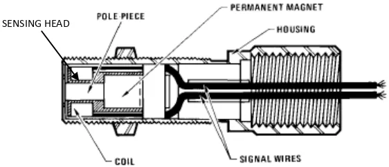
The selected sensor comes from non-contact sensor family called variable reluctance
sensor. The sensing architecture consists of a permanent magnet and two pick-up coil
as shown below.
Figure 2.3. Variable Resistance pick-up sensor SENSING HEAD
[image:22.595.141.422.556.677.2]The reason behind this selection from all other sensor in the market is the simple and
robust design. There are only two working components and there is no contact part.
The sensor is fully encapsulated inside housing that covers all the part to protect it
from the environment. This means it is rigid, reliable and has a relatively long
lifespan. It has been used in automotive industry for crankshaft positioning sensor
and proven its average lifespan is longer than the vehicle itself. It is made from
common material thus the cost is low.
However, there is some problem faced when using this sensor. This sensor operates
based on Faraday’s Law where the output voltage changes linearly with the magnetic
flux variation (produced when toothed steel wheel cut through the flux). From this
law, the output voltage does not increase linearly but produces a continuous
sinusoidal voltage wave form where the frequency varies linearly to the toothed steel
wheel speed. Therefore, a circuitry system needs to be design to process and convert
the frequency input into voltage so it can be displayed on a voltmeter as the rpm
display system.
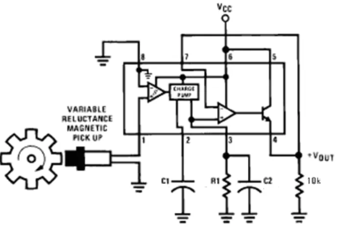
[image:23.595.170.443.479.678.2]2.2.2 The Processing System (LM2907)
8
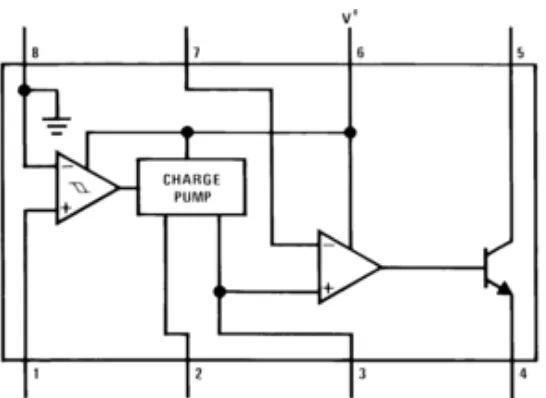
For the signal processing part, a standard part LM2907 is used. It is a frequency to
voltage converter chip with built-in input hysteresis amplifier, charge pump and op
amp/ comparator. The building block for the chip when connected to the sensor will
[image:24.595.144.490.193.429.2]be as follows:
Figure 2.5. LM2907 connection
The operating concept of the circuit will not be explain in detail because it is more on
electronics which is outside the scope of this study. The basic operation of the system
consists of three main components as follows;
(a) Input hysteresis amplifier (signal conditioner)
- amplify the signal, filter the noise, produce binary signal
(on-off) from the sinusoidal wave form.
(b) Charge Pump
- act as a capacitor, collect the voltage signal and discharge it at
a constant rate.
- this bind the frequency to voltage relation, higher frequency =