DEVELOPMENT EFFECTIVE PERMITTIVITY ALGORITHM FOR CONFORMAL STRUCTURE IN 3D FINITE DIFFERENT TIME DOMAIN
(FDTD)
MOHD SHAFIQ IZWAN BIN YAHAYA
This Report Is Submitted In Partial Fulfilment Of Requirement For The Bachelor Degree Of Electronic Engineering ( Telecommunication Electronic) With Honours
Faculty of Electronic and Computer Engineering Universiti Teknikal Malaysia Melaka
ACKNOWLEDGEMENT
Thanks to Allah S.W.T. for giving me a good heath throughout the entire project. I can manage to complete this project with a group of knowledgeable people, researchers, academicians and practitioners. They have contributed a lot towards my understanding and thoughts. I would like to express my sincere appreciation to my supervisor, Mr Fauzi Bin Mohd Johar for his supervision and guidance. His help and support throughout this project is greatly appreciated.
ABSTRACT
This thesis is about developing a conformal object using the finite difference time domain (FDTD) method. Theoretical analysis nowadays frequently uses to analyze problem regarding electromagnetic in computational algorithm. The FDTD method by numerically implemented and time based simulation results in better response of wide band frequency. In the FDTD there are several others principles that have been used in modelling the object; they are absorbing boundary condition (ABC), near Field Far Field (NFFF) and Scattering Parameter. This thesis also uses Radar Cross Section (RCS) characteristic to analyze the radiation pattern of the object at particular incident plane wave direction. The source of the plane wave was determined by the angle of phi and theta in the Matlab function. Once the simulation started, GUI immediately shows simulated object. After FDTD iteration completed the radiation pattern on the polar graph plotted in direction of xy-plane, xz-plane and yz-plane. This pattern can be used to analyze the object characteristic, regarding the frequency of the incident plane wave. From the radiation pattern, we can see that conformal (sphere) show less reflection than the cubical object as comparison.
ABSTRAK
Tesis ini adalah mengenai pembangunan objek konformal menggunakan kaedah beza terhingga masa domain (FDTD). Analisis teori masa kini sering digunakan untuk menganalisia masalah mengenai elektromagnet dalam pengiraan algoritma. Fungsi FDTD adalah dengan melaksanakan kaeda berangka dan simulasi berasaskan masa yang mengakibatkan tindak balas yang lebih baik kepada frekuensi jalur lebar. Dalam FDTD terdapat beberapa kaedah lain yang digunakan dalam membina objek, antaranya Perfect Matched Layer (PML), Absorbing Boundary
Condition (ABC), Near Field Far Field (NFFF) dan Scattering Parameter. Tesis ini
CONTENT
CHAPTER TITLE PAGES
PROJECT TITLE i
REPORT STATUS VERIFICATION FORM ii
STUDENT’S DECLARATION iii
SUPERVISOR’S DECLARATION iv
ACKNOWLEDGEMENT vi
ABSTRACT vii
ABSTRAK viii
CONTENTS ix
LIST OF FIGURES xii
LIST OF TABLES xiv
LIST OF ABBREVIATIONS xv
LIST OF APPENDIX xvi
I INTRODUCTION
1.1 Project Background 1
1.2 Objective 2
1.3 Problem Statement 2
1.4 Scope of Works 3
II LITERATURE REVIEW
2.1 FDTD 9
2.2 CFDTD 15
2.2.1 The Staircasing Problem 17
2.3 Boundary Condition 18
2.3.1 Perfect Electric Conductor (PEC) 19
2.3.2 PMC 20
2.3.3 CPML 14
2.4 Source 22
2.4.1 Plane wave 22
2.5 Scattering Parameter 23
2.6 Radio Cross Section 23
2.6.1 Size and Material 25
III METHODOLOGY
3.1 Flow Chart of Implementation Planning 26
3.2 Flow Chart of FDTD Program 28
IV RESULT AND DISCUSSION
4.1 Introduction 34
4.2 Project Result 35
4.2.1 Scattering from a Dieletric Sphere 39 4.2.2 Scattering from a Dieletric Cube 43 4.2.3 Comparison of Radiation Pattern of Phi and
Theta between Sphere and Cube
45
V CONCLUSION AND SUGGESTION
5.1 Introduction 48
5.3 Future Work 50
REFERENCES 51
APPENDIX A 53
APPENDIX B 54
LIST OF FIGURES
NO TITLE PAGES
1.1.1 Structure modeling boundary condition 7
2.1.1 Yee Cell 10
2.1.2 3D FDTD computational space composed of (Nx x Ny x Nz)
11
2.1.3 Positions of the electric and magnetic fields defined in Yee's FDTD scheme.
12
2.2.1 Cross-sectional view of the quarter of the spherical cavity 16 2.2.1.1 The staircasing appears because P is a node of cell C1, but
not of the
17
2.3.2.1 Boundary conditions enforced for application of FIT. A perfect magnetic conductor
21
2.3.3.1 The CPML on the plane boundary 22
2.6.1 Concept of Radar Cross Section 25
3.1.1 Flow chart overall planning 27
3.2.1 Flow Chart (2) FDTD Overall Program 29
3.2.2 FDTD Program 31
4.2.1 GUI panel 35
4.2.2 GUI after simulation 36
4.2.3 Structure of the staircasing FDTD 37 4.2.4 Structure of the Yu Mittra Equation FDTD 37 4.2.4 Structure form in material mesh 38 4.2.1.1 An FDTD problem space including a dieletric sphere. 39 4.2.1.2 Scattered field captured at the origin and the incident field
waveform
40
4.2.1.4 Biastatic at 1 GHz in the xz plane. 41 4.2.1.5 Bistatic RCS at 1 GHz in the yz plane 41 4.2.1.6 Calculated RCSθ at 1GHz in the xz plane compared with
the analytic solution.
42
4.2.1.7 Calculated RCSø at 1GHz in the yz plane compared with
the analytic solution.
42
LIST OF TABLES
NO TITLE PAGES
LIST OF ABBREVIATION
FDTD - Finite-Different Time Domain
IEEE - Institute of Electrical and Electronics Engineers
HF - High Frequency
2D - Two Dimension
3D - Three Dimension
ABCs - Absorbing Boundary Conditions PML - Perfectly Matched Layer
CPML - Convolutional Perfectly Matched Layer NFFF - Near Field to Far Field
LIST OF APPENDIX
NO TITLE PAGES
A Gant Chart 53
B GUI coding 54
1
CHAPTER I
INTRODUCTION
1.1 Project Background
This project will be exposed to the differential time domain Maxwell equation of Cartesian coordinate to simulate object built by electromagnetic wave. The equations has been used in developing the finite difference time domain method for modeling full wave electromagnetic structure. The advantage of FDTD is simple; implementation of numerical and time based simulation method and resulting in better wide band frequency response.
2
arrays with arbitrary electromagnetic source. FDTD has been used to solve numerous types of problem arising many applications including scattering parameter [2].
Since FDTD is grid based numerical modeling, the simplest technique to build the conformal structure is staircase approximation but it is happening numerical spurious as a result in accurate scattering or radiation characteristic. For instance, to model the curved surface conformal structure like a subcell model and contour path model were proposed. This project will implement the Yu-Mittra model in FDTD algorithm.
1.2 Objective
The objective of this project is:
1. To understand the 3D FDTD method.
2. To model a curve object using 3D FDTD method.
3. To understand and apply the Yu-Mittra theory (CFDTD).
The main objective of this project is to model conformal curve object, where it is more accurate than those generated by the conventional staircasing approach. The staircasing approaches that analyze the objects with curved metallic surfaces using Yee algorithm not only generate spurious solutions, but also introduce errors [3] due to inaccurate approximation of the geometry.
1.3 Problem Statement
3
mathematical models that use some sort of numerical time-stepping procedure to obtain the models behavior over time.
The mathematical solution is represented by a generated table and or graph. Since this is numerical modeling, the FDTD can simulate the structure results algorithms with built-in optimization that allows for rapid virtual prototyping to reduce costly physical prototypes. FDTD is the tool to simulate structure that required and easy to fabricated. The FDTD technique is easy to implement using parallel computation algorithms.
The approach to analyzing objects with curved surfaces using the Yee algorithm is to resort the staircasing to model these surfaces. However, these procedures not only generate spurious solution, but can also introduce errors due to inaccurate approximation of the geometry. Many approaches have been proposed to overcome these difficulties; employing a globally curvilinear grid to model the geometry is one of the solutions. But, it may be may be difficult to generate for an arbitrary shape for the explicit algorithm on these grids requires a special type of mesh. Using the contour path finite difference time domain (CFDTD) scheme is another strategy for handling curved surfaces [4] by deforming the grid only locally to accommodate the curvature of the surface. In this scheme, by using the conventional FDTD procedure certain electric field edges are available and can be updated, while the values of other electric field edge are borrowed from their nearest available collinear edges.
1.4 Scope of works
1. To study application of Maxwell and familiarize Maxwell equation to apply in 3D FDTD. This equation below is representing vector equation.
- Faraday’s law
M E t
B
(1.4.1a)
4
- Ampere’s Maxwell law
J H t
D
D is represent electric displacement fields
H is represent magnetizing fields
(1.4.1b)
- 6 scalar Maxwell’s equations for 3D FDTD
i. x z y
source x
H M dz E y E t H x
1 1 (1.4.2a)
ii. y x z
Msource Hy
dx E z E t H y
1 1
(1.4.2b)
iii. z y x
source z
H M dy E x E t H z
1 1
(1.4.2c)
iv. x z y
Jsource Ex
dz H y H t E
x
1 1
(1.4.2d)
v. y x z
source y
E J dx H z H t E
y
1 1
(1.4.2e)
vi. z y x
Jsource Ez
dy H x H t E
z
1 1
(1.4.2f)
5
From the above equation, the Maxwell‟s will discretized where it analyzed related to time dependent Maxwell‟s equation that introduce by Yee cell. In this method, the partial spatial and time derivates are replaced by a finite difference time domain because in FDTD no matrix operations have to be used. The spatial domain is discritized by two dual orthogonal regular Cartesian grids based on bricks that divide to Δx, Δy, Δz and the time domain is intervals of Δt.
- Disretization of Maxwell’s curls equations in time and space.
i. n k j i x k j i x k j i x n k j i source k j i x n k j i y n k j i y n k j i z n k j i z k j i x n k j i x n k j i x H M z E E y E E t H H
x , ,
, , , , , , , , 1 , , , , , 1 , , , , , , , , , 1 1 2 1 2 1 (1.4.3a) ii. n k j i y k j i y k j i y n k j i source k j i y n k j i z n k j i z n k j i x n k j i x k j i y n k j i y n k j i y H M x E E z E E t H H
y , ,
, , , , , , , , , , 1 , , 1 , , , , , , , , , , 1 1 2 1 2 1 (1.4.3b) iii. n k j i z k j i z k j i z n k j i source k j i z n k j i x n k j i x n k j i y n k j i y k j i z n k j i z n k j i z H M y E E x E E t H H
z , ,
6 iv. 2 1 2 1 2 1 2 1 2 1 2 1 , , , , , , , , , , 1 , , , , , 1 , , , , , , , 1 , , 1 1 n k j i x k j i x k j i x n k j i source k j i x n k j i y n k j i y n k j i z n k j i z k j i x n k j i x n k j i x E J z H H y H H t E E x (1.4.3d) v. 2 1 2 1 2 1 2 1 2 1 2 1 , , , , , , , , , , , , 1 , , 1 , , , , , , , , 1 , , 1 1 n k j i y k j i y k j i y n k j i source k j i y n k j i z n k j i z n k j i x n k j i x k j i y n k j i y n k j i y E J x H H z H H t E E y (1.4.3e) vi. 2 1 2 1 2 1 2 1 2 1 2 1 , , , , , , , , , , , 1 , , , , , 1 , , , , , , 1 , , 1 1 n k j i z k j i z k j i z n k j i source k j i z n k j i x n k j i x n k j i y n k j i y k j i z n k j i z n k j i z E J y H H x H H t E E z (1.4.3f) Where:
7
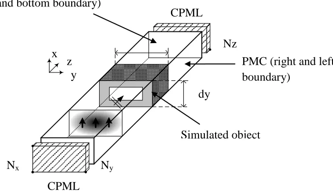
Figure 1.1.1 shows the top and bottom of the structure is the PEC where is refer as the electric field in polarization axis-x. For the magnetic field is located in the right and left of the structure as the axis- y for perfect magnetic conductor (PMC). Convolution perfect matched layer on the structure located at the front and back act as the boundary condition.
[image:23.612.197.536.268.464.2]-Structure modeling boundary layer
Figure 1.1.1: Structure modeling boundary condition
Where the PEC is Perfect Electric Conductor and PMC is Perfect Magnetic Conductor. Nx,Ny and Nz represent the finite value of the structure that unknown.
PMC (right and left boundary)
dy
Simulated object Ny
Nx
CPML
1
Nz CPML
2
8
1. To write 3D FDTD software in MATLAB program using the discretize Maxwell‟s equation consist of the Faraday‟s Law and Ampere‟s Law.
2. Analyze output of the program where is define scattering parameter output for structure in MATLAB software. The output analyzed of the reflection coefficient (S11) is obtained by the simulation in FDTD program.
3. The scattering parameter result will compare with the CST software to compare the reflection coefficient (S11) on the application of the Frequency Selective Surfaces