SUPERVISOR’S ENDORSEMENT
“ I hereby declare that I have read through this report entitle “Modeling and Design of an Active Car Suspension System Using Half Car Model” and found that it has comply the partial fulfillment for awarding the degree of Bachelor of Electrical Engineering (Industrial
Power)”
Signature : ...
Supervisor’s Name : EZREEN FARINA BINTI SHAIR
MODELING AND DESIGN OF AN ACTIVE CAR SUSPENSION SYSTEM USING HALF CAR MODEL
SITI SOLIAH BINTI SELAMAT
A report submitted in partial fulfillment of the requirements for the degree of the Bachelor of Electrical Engineering (Industrial Power)
Faculty of Electrical Engineering
UNIVERSITI TEKNIKAL MALAYSIA MELAKA
STUDENT DECLARATION
I declare that this report entitle “Modeling and Design of an Active Car Suspension System Using Half Car Model” is the result of my own research except as cited in the references.
The report has not been accepted for any degree and is not concurrently submitted in candidature of any other degree.
Signature : ...
Name : SITI SOLIAH BINTI SELAMAT
ACKNOWLEDGEMENT
Praise be to Allah S.W.T to whom we seek help and guidance and under His benevolence we exist and without His help this project could not have been accomplished.
ABSTRACT
ABSTRAK
TABLE OF CONTENTS
CHAPTER TITLE PAGE
ACKNOWLEDGEMENT i
ABSTRACT ii
TABLE OF CONTENTS iv
LIST OF TABLES vii
LIST OF FIGURES viii
LIST OF ABBREVIATIONS x
LIST OF APPENDICES xi
1 INTRODUCTION
1.1Introduction 1
1.2Problem Statement 2
1.3Objectives 2
1.4Scope Project 3
2 LITERATURE REVIEW
2.1Introduction 4
2.2Theory 4
2.2.1 Passive Suspension System 5 2.2.2 Semi-active Suspension System 6
2.2.3 Active Suspension System 7
2.3Previous Study 10 2.3.1 Linear Quadratic Regulator Controller 10
2.3.2 Fuzzy Logic Controller 10
2.3.3 Proportional Sliding Mode Controller 11
2.3.4 Neural Fuzzy Controller 12
2.3.5 PID Controller 12
2.4Conclusion 13
3 METHODOLOGY
3.1Introduction 14
3.2Flowchart of the Project 15
3.3Mathematical Modeling Process 16
3.3.1 Modeling Assumption 17
3.3.2 Model Identifying 17
3.3.3 Free Body Diagram 18
3.3.4 Equation of Motion 18
3.4Vehicle Parameter Setup 26
3.5The Description of Model Disturbance – Road Profile 27
3.6LQR Controller Design 28
3.6.1 LQR 28
3.6.2 State Variable and State Space Representation 29 3.6.3 State Space Controllability 30 3.6.4 State Space Observability 30 3.6.5 Linear Quadratic Regulator Approach 31
3.7Simulations 32
3.7.1 State Space 32
3.7.2 Simulink Blocks 34
4 RESULT AND DISCUSSION
4.1Introduction 37
4.2Results 38
4.2.1 Controller Input 38
4.2.2 Vertical Body Displacement 39 4.2.3 Vertical Wheel Displacement 40
4.2.4 Body Acceleration 42
4.2.5 Stability of the System 43
4.3Conclusion 44
5 CONCLUSION AND RECOMMENDATION
5.1Conclusion 46
5.2Recommendation 47
REFERENCES 48
LIST OF TABLES
TABLE TITLE PAGE
3.1 States and Input Description 17
LIST OF FIGURES
FIGURE TITLE PAGE
2.1 Passive Suspension System 5
2.2 Semi-active Suspension System 6
2.3 Active Suspension System 7
2.4 Block diagram of control for active suspension [5] 8
3.1 The flowchart of the project 15
3.2 Flow diagram of the mathematical modeling [7] 16
3.3 Diagram of Half Car Model [5] 18
3.4 Road Profile [2] 28
3.5 A Typical LQR Controller [2] 29
3.6 Road Profile Block 37
3.7 Passive Suspension System Block 37
3.8 Active Suspension System Block 38
3.9 Comparison of Passive and Active Response Block 39
4.1 Front Controller Input 38
4.2 Rear Controller Input 39
4.3 Front Vertical Body Displacement 40
FIGURE TITLE PAGE
4.5 Front Vertical Wheel Displacement 41
4.6 Rear Vertical Wheel Displacement 42
4.7 Front Body Acceleration 43
LIST OF ABBREVIATIONS
LQR – Linear Quadratic Regulator FLC – Fuzzy Logic Controller
PISMS – Proportional Integral Sliding Mode Controller K – Optimal Feedback Gain
LIST OF APPENDICES
APPENDIX TITLE PAGE
CHAPTER 1
INTRODUCTION
1.1 Introduction
A car suspension system is a system that connects the wheels of the automobile to the body, in such a way that the body is cushioned from jolts resulting from driving on uneven road surfaces. The performance of the suspension system has been greatly increased due to increasing vehicle capabilities. Several performance characteristics have to be considered to achieve a good suspension system. These characteristics deal with the regulation of body movement, the regulation of suspension movement and the force distribution. Ideally the suspension should isolate the body from road disturbances and inertial disturbances associated with cornering and braking or acceleration. The suspension must also be able to minimize the vertical force transmitted to the passengers for their comfort.
1.2 Problem Statement
The suspension system that commonly applied on the vehicle is a passive suspension system in which its spring stiffness and damping value is constant. In the passive suspension system, it damping system has not yet gives a high performance where its vibration amplitude still high and the time required terminating the vibration is quite longer. To overcome this condition, it is then introduced a semi-active and active suspension system. Active suspension system is introduced to improve the riding comfort but the controller need to be design carefully in order to get a good performance due to complexity of the model.
1.3 Objectives
The objectives of this project are:
i. To study and analyze the concept of passive and active car suspension systems using half car model.
ii. To develop controller for active car suspension system for half car model by using MATLAB Simulink.
1.4 Scope Project
CHAPTER 2
LITERATURE REVIEW
2.1 Introduction
Suspension system is a nonlinear and unstable system, thus providing a challenge to the control engineers or researchers. It has become a benchmark to improve ride comfort and road handling. There are many efforts that have been done to develop the controller for this system. Early works and researches on advanced suspension have been carried out by many researchers in the past few decades in order to improve the stability and ride handling performance of the vehicle.
2.2 Theory
2.2.1 Passive Suspension System
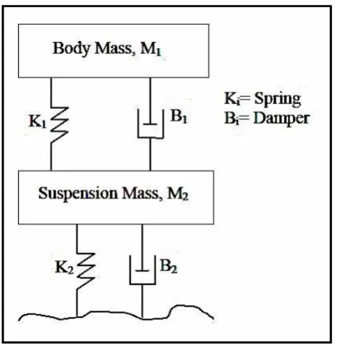
[image:19.595.185.427.335.584.2]Conventional suspension system is also known as a passive suspension system consisting of spring and damper mounted at each wheels of the vehicle in parallel and generally control the motion of the sprung mass (mass of the vehicle body) and also wheel by controlling the relative velocity. Passive suspension systems have a fixed damping characteristic determined by their design, which means the systems do not offer variable damping force and hence better ride comfort and road handling may not be achieved during different maneuvers [1]. Figure 2.1 shows the schematic diagram of the passive suspension system in a quarter car model.
Figure 2.1: Passive Suspension System
wheel) vibration, to provide directional stability during cornering and to maneuver and provide damping for the high frequency vibration induced fire excitations [5].
2.2.2 Semi-active Suspension System
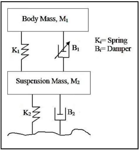
[image:20.595.186.425.470.726.2]Semi-active suspensions on the other hand are less complex, more reliable and commercially available. Semi-active suspension system is quite similar with the conventional suspension system. This kind of suspension has a spring and controllable damper in which the spring element is used to store the energy meanwhile the controllable damper is used to dissipate the energy. Some of the semi-active suspension systems use the passive damper and the controllable spring. The controllable damper usually acts with limited capability to produce a controlled force when dissipating energy [1]. Figure 2.2 shows the schematic diagram of semi-active system with passive spring and controllable damper as a component of suspension.
2.2.3 Active Suspension System
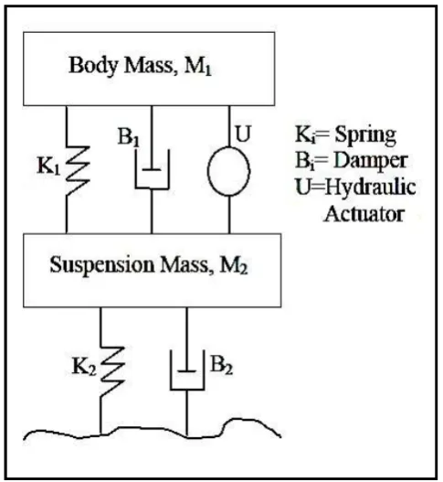
[image:21.595.184.427.274.538.2]Active suspension system has an ability to store, dissipate and to introduce energy to the system. The hydraulic actuator is connected in parallel with a spring and absorber, while the sensors of the body are located at different points of the vehicle to measure the motions of the body [2]. It may vary its parameters depending upon operating conditions. Figure 2.3 shows the active car suspension system.
Figure 2.3: Active suspension system
2.2.4 Active Suspension System Overview
[image:22.595.96.521.325.458.2]Generally, an active suspension has an actuator connected between the sprung and unsprung masses of the vehicle. The actuator mounted between car body and car wheel. Illustration of the active suspension system is shown in Figure 2.4 below. The system consists of hydraulic actuator mounted between car body and car wheel. The actuator can generate control forces which are calculated by a computer to suppress the system responds to the changes of the road condition, thus holding the vehicle in a constant state of equilibrium [5].
Figure 2.4: Block diagram of control for active suspension [5]
The time for the sensors to detect the change and the actuator to respond is a matter of milliseconds is the main reason of many people are not aware of any change in road conditions. The active suspension system must support the car, provide directional control during car handling and provide effective isolation of passengers or payload from road disturbances. There are four important parameters which should be carefully considered in designing a vehicle suspension system which are [1]:
i. Ride comfort whereby directly related to the acceleration sensed by passengers when travelling on a rough road.
ii. Body motion which are known as bounce, pitch and roll of the sprung mass are created primarily by cornering and braking maneuvers. Body motions may be present even on perfectly smooth roads.
iii. Road handling is associated with the contact forces of the tires and the road surface. These contact forces create the necessary friction which prevents the tires from sliding on the road surface. The contact forces are assumed to depend linearly on the tire deflection.
iv. Suspension travel refers to the relative displacement between the sprung and the unsprung masses. All suspension system trade-off the suspension travel for an improved ride comfort.
2.3 Previous Study
2.3.1 Linear Quadratic Regulator Controller
The study shows that an active suspension gives a better performance in terms of comfort ride compared to the passive suspension. An active suspension also increases a tire to road contact in order to make the vehicle more stable. This concludes that LQR controller can be considered one of the solutions for excellent comfort ride and good handling of cars into the new millennium [1].
According to F. Hasbullah and W. F. Faris[2], the LQR controller gives a better performance in terms small percentage overshoot and faster settling time. The study focused on comparison of performance between LQR, fuzzy logic and passive system. The application of the Linear Quadratic Regulator and Fuzzy Logic Controller in the field of active vibration isolation for a vehicle suspension system is presented and the performances of the two active controllers are compared with the passive system. The simulation shown that the fuzzy logic controller needs less force to control the actuator, while the passive system has the smallest percentage overshoot but has the worst settling time [2].
2.3.2 Fuzzy Logic Controller
![Figure 2.4: Block diagram of control for active suspension [5]](https://thumb-us.123doks.com/thumbv2/123dok_us/103678.9666/22.595.96.521.325.458/figure-block-diagram-control-active-suspension.webp)
