Characterisation of Aluminium Matrix Syntactic
Foams under Static and Dynamic Loading
Thesis submitted in accordance with the requirement of the
University of Liverpool for the degree of
Doctor of Philosophy
By
Mohamed Ali Al Tenaiji
i ACKNOWLEDGMENTS
First, I would like to sincere thanks and appreciation to H.H. Sheikh Mohammed bin
Zayed bin Sultan Al Nahyan the Crown Prince of Abu Dhabi and deputy supreme
commander of the UAE Armed Forces, Brig. Matar Al Humairi and Col. Abdul
Munam Al Hashemi for their support and encouragement. Then, my primary supervisor,
Dr. Zhongwei Guan for supervising me as his PhD student. I really value his advice,
support, encouragement, respect, comments and most importantly his patience
throughout the years that I have been working with him. My special thanks to Prof. W.
J. Cantwell and Dr .Y. Zhao for their feedback and motivations throughout this journey.
My sincere gratitude to members of School of Engineering, including Prof. Ahmed
Elsheikh, Mr. Stephen Pennington, Mr. Dave Atkinson as well as my friends in the
Structural Materials and Mechanics Research Group, including Dr. Akram Joda, Dr.
Ahmed Abbas, Dr. Brendan Geraghty, Dr. Mohamad Hassan, Dr. Rafael Celeghini, Ms.
Siti Hajar, Dr. Mohamed Ruzaimi, Mr. Boonkong and Ms. Aziz. I enjoy being with
them. My appreciation is also due to all the staffs and friends in the university that I
have been associating directly or indirectly during my stay at Liverpool.
I am delighted to the love and support of my four beautiful princesses, Noora, Salma,
Mona and Shimaa for giving me the tears and joys all these years. Also, a special
dedication to my lovely wife, Mariya, for her love, support, understanding and patience
throughout the ups and downs in finishing this study. Finally, I would also like to thank
the UAE GHQ of armed forces, UAE military attaché in London and the Government of
ii LIST OF PUBLICATIONS
1. Altenaiji M, Schleyer G and Zhao Y. Characterisation of Aluminium matrix syntactic
foams under static and dynamic loading. Protect 2011: Performance, Protection & Strengthening of Structures under Extreme Loading, Lugano Switzerland, 2011.
2. Altenaiji M, Schleyer G and Zhao Y. Characterisation of Aluminium matrix syntactic
foams under static and dynamic loading. Applied Mechanics and Materials.
2012;82:142-147.
3. Altenaiji M, Guan Z, Cantwell W and Zhao Y. Characterisation of aluminium matrix
syntactic foams under dynamic loading. ICAM2013, Kuala-lumpur Malaysia, 2013.
4. Altenaiji M, Guan Z, Cantwell W, Zhao Y and Schleyer G. Characterisation of
aluminium matrix syntactic foam under drop weight impact. Journal of Materials
iii ABSTRACT
In this study, aluminium matrix syntactic foams reinforced with several types of ceramic
micro-sphere were produced by pressure infiltration. The mechanical properties of a
range of aluminium matrix syntactic foams were investigated in order to optimise the
composition and structure to find the best configuration in terms of high energy
absorption capability, and to validate the finite element predictions against the
corresponding experimental results.
Initially, the compressive behaviour of six different types of aluminium matrix syntactic
foam was evaluated. It was shown that the size of the ceramic micro-spheres, the grade
of the aluminium matrix and the volume fraction of the aluminium matrix all have a
significant influence on the compressive strength and energy absorption capability of the
material. Then, the three-point bending and shear fracture properties of aluminium
syntactic foams were evaluated. These tests indicated that density plays an important
role in determining the stiffness, specific energy absorption and ultimate flexural strain.
Here, it was found that the specific energy absorption related to shear was lower than
that corresponding to flexure. Following this, the behaviour of the syntactic foams under
low velocity impact was characterised and the underlying failure mechanisms were
identified to evaluate their effective mechanical performance. It was found that the
aluminium syntactic foams subjected to drop-weight impact have 20–30% higher
plateau values than samples subjected to the equivalent level of quasi-static
compression. Subsequently, the Split Hopkinson Pressure Bar technique was used to
investigate the behaviour of the material at high strain-rates, which highlighted the
iv
Following this, terminal ballistic tests were conducted to determine the perforation
resistance of the aluminium syntactic foams. The results showed that the syntactic foams
have the ability to prevent the perforation of projectile velocities up to 120 m/s. Finally,
blast tests were performed to investigate the influence of the charge mass and sample
thickness on the dynamic response of the syntactic foams. The results showed that
syntactic foams with a thickness of 14 mm have the capability to sustain a blast load of
4.82 Ns.
Finite element models were developed to simulate the structural behaviour of aluminium
syntactic foams subjected to various quasi-static and dynamic loads. Here, an
elasto-plastic model with both ductile and shear failure criteria was employed to predict the
material performance. The rate-dependent response of the foam was considered by a
stress-ratio based model to take strain-rate effects into account. The numerical
simulations were compared with their corresponding experimental results with
reasonably good correlation. In general, the essential features of the aluminium syntactic
foams tested under different loading regimes were captured by the FE models, including
v
ACKNOWLEDGMENTS ... i
LIST OF PUBLICATIONS ... ii
ABSTRACT ... iii
LIST OF FIGURES ... x
LIST OF TABLES ... xviii
CHAPTER 1 : INTRODUCTION 1.1 Background ... 1
1.2 Aluminium Alloys ... 3
1.3 Ceramic Micro-spheres ... 4
1.4 Matrix Syntactic Foam ... 5
1.5 Motivation and Scope ... 9
1.6 Research Objectives ... 10
1.7 Outline of the thesis ... 11
CHAPTER 2: LITERATURE REVIEW 2.1 Cellular Materials... 13
2.1.1 General ... 13
2.1.2 Types of stochastic foams ... 19
2.1.3 Cell structures... 20
2.1.4 Characterisation of cellular materials... 22
vi
2.1.6 Applications of cellular metallic materials ... 27
2.2 Metal matrix syntactic foams ... 28
2.2.1 Fabrication process... 29
2.2.2 Porosity ... 31
2.2.3 Density ... 32
2.2.4 Dynamic compressive testing of matrix syntactic foams ... 34
2.2.5 Low velocity dynamic loading ... 34
2.2.6 High velocity dynamic loading ... 35
2.3 The finite element modelling ... 41
2.3.1 Abaqus/Standard ... 42
2.3.2 Abaqus/Explicit ... 42
2.3.3 Modelling of foams ... 42
2.4 Summary ... 43
CHAPTER 3: MATERIALS AND EXPERIMENTAL METHODS 3.1 Materials ... 44
3.1.1 Aluminium matrix (6082-T6) syntactic foam ... 44
3.1.2 Aluminium matrix (7075-T6) syntactic foam ... 47
3.2 Manufacturing methods (Fabrication of the metal matrix syntactic foams) ... 48
3.3 Mechanical properties of the aluminium matrix syntactic foams ... 51
vii
3.3.2 Micro-structural observations ... 52
3.3.3 Quasi-static testing ... 52
3.3.4 Dynamic Testing ... 55
3.4 Summary ... 70
CHAPTER 4: EXPERIMENTAL RESULTS AND DISCUSSION 4.1 Morphology and Microstructure of the Aluminium Syntactic foam ... 71
4.2 Characterising the Behaviour of the Aluminium Syntactic Foam under Quasi-static Loading ... 75
4.2.1 Compression response of the aluminium matrix syntactic foam ... 75
4.2.2 Flexural response of the aluminium matrix syntactic foam ... 85
4.2.3 Shear response of the aluminium matrix syntactic foam ... 92
4.3 Characterising the Behaviour of the Aluminium Syntactic Foam at Higher Strain Rates ... 101
4.3.1 The compression behaviour of the syntactic foams under low velocity impact ... 101
4.3.2 The compression behaviour of the syntactic foams under high velocity impact ... 107
4.3.3 Behaviour of the syntactic foams under terminal ballistic impact ... 112
4.3.4 Behaviour of the syntactic foams during blast loading ... 116
viii
CHAPTER 5: FINITE ELEMENT MODELLING
5.1 Constitutive Models for Aluminium Matrix Syntactic Foam ... 122
5.1.1 Isotropic elasticity ... 123
5.1.2 Plasticity ... 123
5.1.3 Damage evolution ... 125
5.2 Materials ... 127
5.3 FE Modelling at Quasi-static rates ... 129
5.3.1 Simulation of the Compression Tests ... 130
5.3.2 Three-point bending simulation ... 134
5.3.3 Simulation of the shear tests ... 135
5.4 Dynamic FE Modelling Procedures ... 136
5.4.1 Simulation of the drop-weight tests ... 136
5.4.2 Split Hopkinson Pressure Bar simulation ... 139
5.4.3 Simulation of the terminal ballistic tests ... 142
5.4.4 Blast test simulation ... 143
5.5 Summary ... 145
CHAPTER 6: FINITE ELEMENT SIMULATION RESULTS AND DISCUSSION 6.1 Modelling the Quasi-static Compression ... 146
ix
6.3 Modelling the Shear Tests ... 151
6.4 Modelling the Drop-weight Impact Response ... 153
6.5 Modelling Results of the Split Hopkinson Pressure Bar ... 156
6.6 Simulation of the Terminall Ballistic ... 158
6.7 Blast Modelling ... 163
6.8 Summary ... 168
CHAPTER 7: Conclusions and Recommendations for Future Work 7.1 General Summary ... 170
7.2 Recommendations for Future Work... 173
x LIST OF FIGURES
Figure 1.1. (a) Microstructure of aluminium foam; (b) microstructure of aluminium
matrix syntactic foam. ... 2
Figure 1.2. Hollow and porous ceramic microspheres (Walsh, 1997). ... 5
Figure 1.3. Schematic representation of the syntactic foam showing matrix porosities (Gupta and Ricci, 2006). ... 6
Figure 1.4. Schematic of the preparation of a metal syntactic foam by pressure infiltration (Zhang et al., 2009). ... 7
Figure 1.5. Photograph of syntactic foam autonomous underwater... 8
Figure 1.6. Photograph of a syntactic foam blast mitigating material (Trelleborg AEM). 9 Figure 2.1. Hierarchical descriptions of cellular materials classification ... 15
Figure 2.2. Solid and hollow lattice truss structures (Zhu et al., 2010). ... 17
Figure 2.3. Two views of metal textile structures (Wadley, 2002). ... 17
Figure 2.4. Classification of application of cellular materials (Banhart, 2001). ... 18
Figure 2.5. Open-cell aluminium metal foam (Chou and Song, 2002). ... 19
Figure 2.6. Closed-cell aluminium metal foam (Miyoshi et al., 1999). ... 20
Figure 2.7. Eight cells, forming a fundamental unit of a Weaire-Phelan foam ... 21
Figure 2.8. An example of a stress–strain curve for an elastic-plastic foam ... 23
Figure 2.9. An example of a loading and unloading stress–strain curve for a cellular foam... 24
Figure 2.10. Stress–strain curve for an energy absorbing material ... 26
Figure 2.11. Metal foams in the automotive industry (Fraunhofer, 2008). ... 27
xi
Figure 2.13. Various steps in the infiltration casting method (Evans et al., 2003). ... 30
Figure 2.14. Variation in plateau stress with density of the syntactic foams (Rohatgi et al., 2006). ... 33
Figure 2.15. Shock wave pressure (Ngo et al., 2007). ... 39
Figure 2.16. Conventional ballistic pendulum. ... 41
Figure 3.1. Schematic of melt infiltration casting. ... 49
Figure 3.2. Three point bending test. ... 53
Figure 3.3. Fixture of the shear test... 55
Figure 3.4. The drop-weight test facility at the University of Liverpool. ... 56
Figure 3.5. Schematic of the SHPB test fixture (Kolsky, 1949). ... 58
Figure 3.6. Schematic of the changes in material properties and the cross-sectional area of bars/sample SHPB. ... 59
Figure 3.7. Schematic of forces on the SHPB specimen... 61
Figure 3.8. Small ballistic experimental range, Cranfield University. ... 65
Figure 3.9.The projectile that was used 7.62 x 39 mm AK47. ... 65
Figure 3.10. Target clamped to the stand. ... 66
Figure 3.11. Photograph of the ballistic pendulum at the University of Cape Town. .... 67
Figure 3.12. Photograph of a disc-shaped PE4 explosive. ... 68
Figure 3.13.Photograph of disc-shaped PE4 explosive with a 0.5 g leader attached to the detonator. ... 69
Figure 4.1. Optical micrograph of the aluminium matrix syntactic foam CM (I). ... 72
Figure 4.2. Optical micrograph of the aluminium matrix syntactic foam CM (II). ... 72
xii
Figure 4.4. Density of aluminium syntactic foam for different sizes of ceramic
micro-spheres and different aluminium matrix grades. ... 74
Figure 4.5. The calculated and measured densities of the aluminium syntactic foam for
different sizes of ceramic micro-spheres... 74
Figure 4.6. A typical stress–strain trace following quasi-static testing on the aluminium
matrix syntactic foam sample CM (VI). ... 76
Figure 4.7. Typical average stress–strain curves following quasi-static tests on the
aluminium matrix syntactic foams. ... 77
Figure 4.8. Comparison of the compressive response of the aluminium matrix syntactic
foam for two volume fractions of aluminium matrix. ... 79
Figure 4.9. Photograph of the failure of the aluminium matrix syntactic foam; (a)
aluminium matrix percentage of 50%; (b) aluminium matrix percentage of 33%. 80
Figure 4.10. The variation of the plastic collapse stress with density for different
syntactic foams. ... 81
Figure 4.11. The variation in compressive modulus with density for different syntactic
foams. ... 82
Figure 4.12. The variation in plateau stress with density for different syntactic foams. 82
Figure 4.13. Plot of the specific energy absorption vs. density for different syntactic
foams. ... 83
Figure 4.14. Stress–strain traces for aluminium (7075-T6) syntactic foam at different
strain-rates. ... 84
xiii
Figure 4.16. Plot of the maximum deflection vs. density for different syntactic foams.
... 88
Figure 4.17. Plot of peak load vs. density for different syntactic foams... 89
Figure 4.18. Plot of the stiffness vs. density for different syntactic foams. ... 89
Figure 4.19. Plot of the tangent modulus vs. density for different syntactic foams... 90
Figure 4.20. Plot of the flexural strength vs. density for different syntactic foams. ... 91
Figure 4.21. Plot of the specific energy absorption vs. density for different syntactic foams. ... 92
Figure 4.22. Shear response of the aluminium matrix syntactic foam. ... 93
Figure 4.23. Plot of the maximum displacement vs. density for different syntactic foams. ... 95
Figure 4.24. Plot of the peak load vs. density for different syntactic foams. ... 96
Figure 4.25. Plot of the stiffness vs. density for different syntactic foams. ... 97
Figure 4.26. Plot of the shear modulus vs. density for different syntactic foams. ... 98
Figure 4.27. Plot of the shear strength vs. density for different syntactic foams. ... 99
Figure 4.28. Plot of the fracture strain vs. density for different syntactic foams. ... 100
Figure 4.29. Low velocity impact response of aluminium matrix syntactic foam CM (III) at different impact velocities. ... 103
Figure 4.30. Dynamic and quasi-static stress–strain curves for the aluminium syntactic ... 104
xiv
Figure 4.32. Plots of the specific energy absorption by the aluminium syntactic foams
CM (I), CM (II) and CM (III) at different strain rates. ... 106
Figure 4.33. Voltage pulses acquired from the incident and transmitted bars. ... 107
Figure 4.34. Compressive stress–strain curves for the aluminium matrix syntactic foam at high strain-rates. ... 110
Figure 4.35. Plot of the variation of specific energy absorption with strain-rates. ... 110
Figure 4.36. Plot of the variation of plateau stress with strain rates. ... 111
Figure 4.37. Plots of the peak stress for different sensitivity parameter values... 111
Figure 4.38. Penetration into aluminium syntactic foam vs. strike velocity. ... 113
Figure 4.39. Initial versus residual velocity for samples impacted by 7.62 mm spheres for different plate thickness. ... 115
Figure. 4.40 Photographs of penetrated and perforated plates of aluminium syntactic foam... 115
Figure 4.41. Residual velocity vs. plate thickness at different initial velocities. ... 116
Figure 4.42. The variation of impulse with mass of PE4 for a constant stand-off distance 180 mm at different sample thickness. ... 118
Figure 4.43. The permanent displacement vs. impulse for a constant stand-off distance of 180 mm. ... 118
Figure 4.44. Photographs of plate profiles showing the permanent deflection at the centre of the plate due to localised loading. ... 120
Figure 5.1. Mesh, boundary and loading conditions used in modelling compression testing on the aluminium syntactic foam. ... 130
xv
Figure 5.3. Mesh and loading conditions used in modelling the three-point bending test
on the aluminium syntactic foam. ... 134
Figure 5.4. Mesh, boundary and loading conditions used in shear modelling of the foam.
... 135
Figure 5.5. Boundary and loading conditions used in the SHPB test of aluminium
syntactic foam. ... 139
Figure 5.6. Mesh and loading conditions used in the terminal ballistic test on aluminium
syntactic foam. ... 143
Figure 5.7. Boundary, geometry and loading conditions used in the blast modelling of
the aluminium syntactic foam. ... 144
Figure 6.1. Stress-strain traces for the aluminium matrix syntactic foam Al 7075-T6 with
different sizes of ceramic mirco-spheres under quasi-static compression loading: a)
25-75 μm, b) 125-250 μm, c) 250-500 μm (the solid line represents experimental
results and the dashed line represents FE simulation). ... 148
Figure 6.2. Comparison of the tested foam (Al 7075-T6 with 125-250 μm ceramic
microspheres) with the simulated foam. ... 148
Figure 6.3. Load-displacement traces for the aluminium matrix syntactic foam Al
7075-T6 with different sizes of ceramic micro-spheres under three point bending loading:
a) 25-75 μm, b) 125-250 μm, c) 250-500 μm (the solid line represents
experimental results and the dashed line represents FE simulation)... 150
Figure 6.4. Load-displacement traces for the aluminium matrix syntactic foam Al
xvi
b) 125-250 μm, c) 250-500 μm (the solid line represents experimental results and
the dashed line represents FE simulation). ... 152
Figure 6.5. Comparison of the tested foam (Al 7075-T6 with 125-250 μm ceramic
microspheres) with Von Mises stress distribution, (in MPa), for the simulated
foam... 153
Figure 6.6. Load-displacement traces for the aluminium matrix syntactic foam Al
7075-T6 with different sizes of ceramic micro-spheres under dynamic loading at
different strain rates: a) 25-75 μm, b) 125-250 μm, c) 250-500 μm (the solid line
represents experimental results and the dashed line represents FE simulation). .. 155
Figure 6.7. Comparison of the tested foam (Al 7075-T6 with 250-500 μm ceramic
microspheres at strain rate of 204 1/s) with the simulated foam... 156
Figure 6.8. Stress-strain traces for aluminium matrix syntactic foam CM (I) under
dynamic loading of SHPB at different strain rates: a) 1517 1/s, b) 1547 1/s, c) 1578
1/s (the solid line represents experimental results and the dashed line represents FE
simulation). ... 158
Figure 6.9. Predicted velocity time histories for the aluminum matrix syntactic foam
impacted above V50. ... 160
Figure 6.10. Experimental and FE predions results of VR vs. VI. ... 160
Figure 6.11. FE predicted energy histories for the aluminum matrix syntactic foam
impacted above V50. ... 161
Figure 6.12. Energy absorption per thickness and ballistic limit versus the ratio of
sample thickness to projectile diameter. ... 161
xvii
Figure 6.14. Penetration of a 10 mm aluminium matrix syntactic foam at an impact
velocity of 120 m/s. ... 162
Figure 6.15. Comparison of the predicted centre deflection with the experimental results
for different blast charges at different sample thickness (zero deflection represents
the explode material). ... 165
Figure 6.16. (a) Centre displacement and (b) velocity on the front and back faces of 10
mm the aluminum syntactic foam CM (I). ... 166
Figure 6.17. Comparison between the experiments and numerical simulations for 3 mm
thickness of aluminum syntactic foams at 2 Ns. ... 166
Figure 6.18. Comparison between the experiments and numerical simulations for the 14
xviii LIST OF TABLES
Table 3.1. Physical and mechanical properties of Al 6082-T6. ... 45
Table 3.2. Chemical composition and technical specification of the micro-spheres. ... 46
Table 3.3. Technical specifications of the micro-spheres. ... 46
Table 3.4. Physical and mechanical properties of Al7075-T6 ... 48
Table 3.5. Composition of the aluminium syntactic foams. ... 50
Table 3.6. Details of the high speed video camera. ... 57
Table 3.7. Mass of the ballistic pendulum and its components. ... 68
Table 3.8. Composition of PE4 ... 69
Table 3.9. Summary of the experimental details... 70
Table 4.1. Average mechanical properties of the aluminium matrix syntactic foam. .... 77
Table 4.2. Average flexural properties of the aluminium matrix syntactic foams. ... 85
Table 4.3. Average shear properties of the aluminium matrix syntactic foam. ... 93
Table 4.4. Summary of the aluminium matrix syntactic foam samples used in the low velocity impact tests. ... 102
Table 4.5. Results following low velocity impact tests on the aluminium matrix syntactic foams CM (I), CM (II) and CM (III)... 102
Table 4.6. Average high-velocity impact properties of aluminium matrix syntactic foams (CM (I), CM (II) and CM (III)). ... 108
xix
Table 4.8. Average terminal ballistic properties of the aluminium matrix syntactic foam.
... 113
Table 4.9. Summary of the mass of explosive used during testing when the stand-off
distance was 180 mm. ... 117
Table 4.10. Summary of the mass of explosive used during tests with a steel front plate.
... 119
Table 5.1. Summary of the elastic properties of the aluminium matrix foam material. 128
Table 5.2. Summary of the plasticity properties of the aluminium matrix syntactic
foams. ... 128
Table 5.3. Summary of ductile and shear damage behaviout for the aluminium matrix
syntactic foams. ... 129
Table 5.4. Summary of the elastic properties of the aluminium matrix foams used in the
drop-weight modelling. ... 137
Table 5.5. Summary of the plasticity properties of the aluminium matrix syntactic foams
used in the drop-weight modelling. ... 138
Table 5.6. Summary of ductile and shear damage parameters for the aluminium matrix
syntactic foams used in the drop-weight modelling. ... 138
Table 5.7. Summary of rate dependent of hardening yield ratio for the aluminium matrix
syntactic foams used in the drop-weight modelling. ... 139
Table 5.8. Summary of the elastic properties of the aluminium matrix foams used in the
SHPB modelling. ... 140
Table 5.9. Summary of the plasticity properties of the aluminium matrix syntactic foams
xx
Table 5.10. Summary of ductile and shear damage parameters for modelling the
aluminium matrix syntactic foams under SHPB testing. ... 141
Table 5.11. Summary of rate dependent of hardening yield ratio for the aluminium
1
CHAPTER 1 : INTRODUCTION
This chapter contains a brief introduction to aluminium matrix syntactic foams,
aluminium alloys and ceramic micro-spheres, along with their applications. Additionally,
this chapter discusses matrix syntactic foam, which covers types of matrix and ceramic
microspheres, the method of fabrication and the effect these parameters have on the
material response under static and dynamic loading. Moreover, the chapter also discusses
the motivation and scope of the research herein and the aims and objectives of the study,
as well as gives a detailed outline of the thesis.
1.1 Background
The impact and shock resistance of engineering structures is currently of great interest to
the engineering community and government agencies. This is primarily due to the urgent
need to provide protection against possible terrorist attacks. Development of lightweight,
strong and ductile materials to be used in making military vehicles for this purpose is a
formidable challenge facing the materials community. Under blast or impact loading, a
structure may undergoes large plastic deformations leading to partial or total failure. The
important characteristics (Hanssen et al., 2002) of such a structural response are: i)
deformation mode and failure mode; ii) impulse and shock wave transfer; and iii) energy
absorption through plastic deformation.
Aluminium foams have become more important due to their physical and mechanical
properties (Banhart, 2001). However, the foaming process can have a detrimental effect
2
restricted to instances where compressive strength is not the primary design criterion due
to their lower mechanical properties compared to the base metal, such that they cannot be
used as load-bearing materials (Gibson and Ashby, 1999). An alternative method to
enhance the Young’s modulus and strength of the foam has been developed, which
incorporates porosity in materials using hollow particles as fillers to produce a syntactic
foam (Kiser et al., 1999). The difference between aluminium foam and aluminium matrix
syntactic foam is that the hollow particles in the syntactic foam are infiltrated by the
matrix, whereas the hollow particles in conventional foams are filled by air, as shown in
Figure 1.1.
Figure 1.1. (a) Microstructure of aluminium foam; (b) microstructure of aluminium matrix syntactic foam.
The material used in this research is an aluminium matrix syntactic foam. Aluminium
matrix syntactic foam is a type of composite material. It has a porous structure consisting
of a metal matrix filled with ceramic microspheres. Metal matrix syntactic foam has a
higher compressive strength than a polymer matrix syntactic foam and a superior energy
absorption capacity to that of aluminium foam, primarily due to its higher plateau
strength and densification strain. The compressive strength of the material is related to
the energy absorption capability of foams and is usually quantified by using measurable
a b
3
stress–strain relationships. Syntactic foams usually show a long and flat stress–strain
curve after initial yielding. The cell walls experience a continuous plastic collapse at a
critical value, known as the ‘plateau stress’, until the material reaches a nominal
densification strain (εD). The best energy-absorbing material therefore must have the
longest plateau before reaching this strain. These material specifications highlight the
properties that should be chosen to withstand high strain-rate loading.
1.2 Aluminium Alloys
Aluminium alloys are alloys of which aluminium is a dominant metal. Typically, the
alloying elements in aluminium alloys include zinc, silicon, manganese, magnesium and
copper. Their strength to weight ratio makes them a preferred choice for aerospace and
other industries, where weight needs to be minimised. Aluminium alloys possess a
variety of characteristics that make them useful materials for engineering structures. For a
particular application, choosing the correct alloy requires consideration of its corrosion
resistance, weldability, workability, formability, ductility, density, tensile strength and
mechanical stiffness. The versatility of its properties renders aluminium the most widely
used metal after steel. Approximately 29 million tonnes of aluminium are produced
worldwide every year. Three quarters of this material is produced as a new material,
whereas the remainder is produced by recycling, thereby saving energy. Aluminium is
one of the lightest metals, with a strength to weight ratio greater than that of steel.
Aluminium exhibits various properties resulting in it being used in transport, packaging,
4
excellent strength to weight ratio of aluminium alloy makes it a prime material for the
construction of trains, military vehicles, ships and aircraft.
The properties that give aluminium its versatility for these applications are as follows:
lightweight;
corrosion resistance;
electrical and thermal conductivity;
ductility.
In addition to all the advantages that are offered by aluminium, it also has some
drawbacks, which are as follows:
it is not as strong as steel;
it is easily oxidised;
it is not hard and scratches easily;
it is more expensive than steel.
1.3 Ceramic Micro-spheres
Ceramic micro-spheres have two different inner structures, either porous or hollow. Both
types have the same effective density and porosity. The shape of each ceramic
micro-sphere is different. The hollow ceramic micro-micro-spheres have a perfect spherical shape,
while porous ceramic micro-spheres have a roundish shape with a rough surface as shown
5
Figure 1.2. Hollow and porous ceramic microspheres (Walsh, 1997).
Ceramic micro-spheres are semi-transparent, with a fine particle size and a high strength.
They are ideal for improving both hardness and filler loading, while at the same time
providing gloss control. Ceramic micro-spheres offer a number of advantages owing to
the following properties:
low weight and volume;
low thermal conductivity;
transparency to UV down to 250 nm;
high filler loadings due to their inert nature.
The main disadvantage of ceramic micro-spheres is their failure to absorb energy, which
in turn affects their material properties.
1.4 Matrix Syntactic Foam
Matrix syntactic foams are composite materials that consist of a matrix incorporating
porous or hollow ceramic particles. This type of foam is a new classification of materials
that can be produced using several metals or polymer matrices and ceramic
micro-spheres. It consists of a metal matrix with ceramic micro-spheres embedded in the matrix.
6
ceramic micro-spheres can be a porous or hollow structure. In contrast, hollow metal
spheres are rarely used. The size of the hollow ceramic micro-spheres determines the
porosity of the matrix syntactic foam, as shown in Figure 1.3.
Figure 1.3. Schematic representation of the syntactic foam showing matrix porosities (Gupta and Ricci, 2006).
A matrix syntactic foam is considered as a light material with a high energy absorption
capacity. Researchers (Rohatgi et al., 2011; Luong et al., 2013) have studied metal matrix
syntactic foams, with a particular focus on the compressive behaviour and fabrication of
these materials. The most commonly used method for manufacturing metal matrix
syntactic foams is the melt infiltration (Tao and Zhao, 2009). In this method, molten
7
Figure 1.4. Schematic of the preparation of a metal syntactic foam by pressure infiltration (Zhang et al., 2009).
The volume fraction of the metal matrix to the ceramic micro-spheres has been studied by
Orbulov (Orbulov and Majlinger, 2010). The volume fraction of the metal matrix can be
reduced by embedding ceramic spheres with size distributions that are multimodal in
nature. This increases the foam porosity. However, these types of foam deform under
compression in a brittle mode, either by cracking or by shear, due to a high percentage
volume of ceramic micro-spheres (Balch and Dunand, 2006). The brittle deformation can
lead to a significant reduction in the plateau strength and energy absorption.
In comparison with fully dense alloys and metals, metal matrix foams show a high
specific stiffness, a low density and a mechanical damping capacity, a high energy
absorption capacity. This combination of characteristics makes metal foams an appealing
choice for functional applications, as well as structural applications. Structural or
functional applications of metal foams include sound-damping and fire-proof panels,
foam sandwich cores, underwater buoyant structures and energy-absorbing packaging.
8
embedded in a continuous matrix. These types of silica-alumina/aluminium spheres and
alumina/aluminium spheres foams have a higher density as compared with the traditional
aluminium foams that are manufactured, for example, by salt infiltration or gas
entrapment in the melt. Moreover, they offer a high energy-absorption capability,
isotropic mechanical properties and a high strength. Additionally, their closed cell
geometry is appealing for its insulating and mechanical properties (Balch and Dunand,
2006).
Metal matrix syntactic foams are used in a variety of applications. For example, they are
typically used in lightweight structures such as boat hulls, buoyancy modules for marine
riser tensioners and autonomous underwater vehicles (AUV) in the marine industry, as
shown in Figure 1.5 (Kudo, 2008).
Figure 1.5. Photograph of syntactic foam autonomous underwater vehicle (Trellborg AEM).
Metal matrix syntactic foams are used as building materials such as acoustic isolation
materials for rooms, artificial marble, wood and so forth. In addition, they are used in the
automotive industry as bumpers for vehicles and as protective materials for the packaging
industry, due to their high energy-absorption characteristics (Walsh, 1997). Other
acoustically-9
attenuating materials and radar-transparent materials. In addition, aluminium matrix
syntactic foam is found to have a higher damping capacity than the matrix alloy (Rohatgi
et al., 2011). Also, Zhang et al. (2009) suggest the use of aluminium matrix syntactic
foams in crash energy absorption zones (Zhang et al., 2009).
Figure 1.6. Photograph of a syntactic foam blast mitigating material (Trelleborg AEM).
1.5 Motivation and Scope
Due to the limited knowledge of the characteristics of aluminium matrix syntactic foams
under static and dynamic loading, this research aims to firstly undertake an experimental
and finite element investigation into the response of such materials under quasi-static
compression, three-point bending and shear loading. Following this, the dynamic
response of the material will be studied under low and high velocity impact as well as
under blast loading. The prediction of the load carrying capacity and energy absorption
10
1.6 Research Objectives
The main objective of this research is to investigate the best possible combination of
aluminium matrix and ceramic micro-spheres for producing an energy-absorbing material
that could be used in armoured vehicles. This objective will be achieved by fulfilling the
following sub-objectives.
Fabrication of different types of aluminium matrix syntactic foams
Identify the best combination of the aluminium matrix and ceramic micro-spheres for
producing high energy absorption materials.
Characterisation of the syntactic foams under dynamic and static loading
A series of experimental tests will be conducted to investigate the behaviour of
aluminium matrix syntactic foams under static and dynamic loading, which include the
energy absorption capability of the aluminium syntactic foams at very high strain-rate
loading.
Use of the finite element (FE) analysis
Finite element models will be developed to simulate the structural response of aluminium
matrix syntactic foams under both static and dynamic loading. All models will be
validated against the corresponding experimental results. It is expected that FE models
will be used simulate a large number of cases which are not covered in the experimental
11
Studies on the effect of the tests on material parameters and performance
Parametric studies using the validated FE models will be conducted on aluminium matrix
syntactic foams. This is to analyse the effects of the sample dimensions, the size of the
ceramic micro-spheres, the type of aluminium alloy, projectile velocity and explosive
charge size on the response of the material.
1.7 Outline of the thesis
To achieve the objectives stated above, i.e. to acquire the best combination of aluminium
matrix and ceramic micro-spheres for the synthesis of a high-strain rate energy absorbing
material and to use numerical analyses to predict the response of aluminium matrix
syntactic foams under quasi-static and dynamic loading, the thesis is divided into seven
chapters as follows.
Chapter 1 explains the significance of this work, as well as highlighting its main
aim and the associated objectives for achieving the benefits of this study.
Chapter 2 presents a literature review, focusing on relevant experimental work,
theoretical analysis and numerical modelling of the aluminium matrix syntactic
foam. Attention is focused on the characterisation of the material response under
static and dynamic loading.
Chapter 3 describes the experimental work conducted in this research. It is divided
into three sections: the fabrication procedures to manufacture different types of
aluminium matrix syntactic foams and the characterisation of the syntactic foams
12
Chapter 4 presents and discusses the results obtained following tests on
aluminium matrix syntactic foams.
Chapter 5 describes the FE models using Abaqus/Standard and Abaqus/Explicit
that are used in this research. This covers the simulations of the quasi-static and
dynamic responses of aluminium matrix syntactic foams.
Chapter 6 presents and discusses the simulation results obtained from numerical
modelling on aluminium matrix syntactic foams.
Chapter 7 presents the conclusions drawn from this study and the recommendations
13
CHAPTER 2: LITERATURE REVIEW
Over the past ten years, a wide range of polymeric and metallic cellular materials have
been manufactured, with the goal of developing structures that are lightweight in nature.
These are typically sandwich structures and are sufficiently strong. Such materials can be
thought of as composites that are porous and constituted of spaces, which are connected
with struts, shells or plates. Due to their high specific strength, low weight, good energy
dissipation and high specific toughness features, they have found applications as the core
in sandwich structures on a frequent basis. Commonly in such structures, the core should
sustain crushing or indentation. On the other hand, the face-sheets offer bending strength
to the structure. There are many studies available on the behaviour of metal foams in
sandwich structures under different loading conditions; however, they are scattered
throughout the literature. This chapter attempts to consolidate the literature in this field.
2.1 Cellular Materials
2.1.1 General
By definition, cellular materials are composites consisting of a solid material (e.g. a
metal, or a polymer) and air in the formed cells. They consist of a network of solid ribs or
plates, which are made up of lightweight materials that have the advantage of
strength/weight ratio and stiffness/weight ratio over the solid material (Zhang, 2001). The
properties of such materials are primarily dependent upon the shape and structure of the
cells.
Man-made cellular materials can exist either in the form of a two-dimensional
14
coral, leaves, bone and cancellous materials, etc. have a cellular structure. Such materials
are usually efficient at absorbing energy and possess low densities. Primarily, the level of
porosity within the material controls the energy absorption process.
Cellular materials and their properties have been explored extensively by researchers in
previous decades (Gibson and Ashby, 1999). Over the past decade, metallic foams have
been developed with a high porosity and have been used as engineering materials for the
development of lightweight structures, typically sandwich-type structures, with adequate
stiffness and strength (Davies and Zhen, 1983). Recently, there has been much research
and numerous attempts to evaluate the properties, production methodologies and potential
applications of such types of cellular material. These studies and researches have been
widely reported in the literature (Davies and Zhen, 1983).
For the past ten years, a wide range of polymeric and metallic cellular materials have
been created with the objective of developing lightweight structures (Zhu et al., 2010).
The majority of these are sandwich structures. Cellular materials have high a strength and
are lightweight with good energy-dissipation properties. For these reasons, they are often
used as the core in a sandwich structure. In such structures, the core primarily sustains
crushing or indentation, whereas the face sheets confer the structure with bending
strength. Today, sandwich structures are used on a large scale in a broad variety of
applications, such as packaging, ship manufacture, vehicle manufacture and in the
defence industries. Cellular metals, which have microstructures and are stochastic in
nature, can sustain enormous plastic deformation at a fixed level of stress (Zhu et al.,
2010). Due to their extremely high energy absorption capabilities, such types of material
15
discussed in the following section, these being honeycombs, metal foams and textile and
truss-based lattice materials.
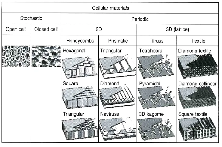
Cellular materials can be classified into stochastic cells and periodic cells, depending on
the topologies and geometry of their microstructure (Zhu et al., 2010). Stochastic cells
have a random microstructure that can either be open or closed. On the other hand,
periodic cells have two-dimensional channels, like a honeycomb structure or a
three-dimensional structure, such as that of a truss or textile. The classification scheme of
[image:36.612.143.512.294.539.2]cellular materials is illustrated in Figure 2.1.
Figure 2.1. Hierarchical descriptions of cellular materials classification (Zhu et al., 2010).
2.1.1.1 Metal foams
Metal foams are amongst the most significant type of cellular materials. Metal foams are
16
contains metals that have gas-filled pores as the solid material. The pores can be sealed in
a similar way to that found in closed-cell devices. Additionally, the pores can be
fashioned to form an interconnected network in a similar manner to open-cell foams.
Metal foams have been reported to possess a range of physical and mechanical properties
(Ashby et al., 2000). Cellular materials that have stochastic or periodic microstructures
are configured to the core of sandwich panel structures (Zhu et al., 2010). The strength of
a metal that is foamed has a proportional relationship to its density. A twenty percent
dense material is twice as strong as ten percent dense material.
2.1.1.2 Syntactic foams
A syntactic foam is a type of composite material that has a low density and a higher
strength and stiffness than metal foams. It can be produced by infiltrating molten metal
into hollow ceramic spheres (Banhart, 2001).
2.1.1.3 Honeycombs
A honeycomb is composed of plates or sheets that form the edges of the unit cell. They
can be configured in a different manner by rearranging the shape and size of the cells.
The cells can be square, triangular, rectangular, hexagonal, circular or diamond shaped.
Honeycomb materials can be used in heat exchangers, for energy absorption as well as in
building constructions (Zhu et al., 2010).
2.1.1.4 Trusses and textiles
Trusses and textiles belong to a class of three-dimensional cellular materials. There are
17
of struts that meet at a node, while textile structures consist of woven metal wires, which
are bonded together, as shown in Figures 2.2 and 2.3, respectively.
Figure 2.2. Solid and hollow lattice truss structures (Zhu et al., 2010).
Figure 2.3. Two views of metal textile structures (Wadley, 2002).
Cellular materials can be used in a variety of applications. The choice of foam is based on
the porosity (opened or closed cells), the size of the pores and the type of solid-material
(metal, alloy, etc.). It has been noted that in the majority of applications the medium,
18
Therefore, these pores may need to have different degrees of connectivity. A few may
require fully open cells to facilitate a high rate flow of fluid, whereas others may require
partially open cells. On the other hand, in applications such as load-bearing structural
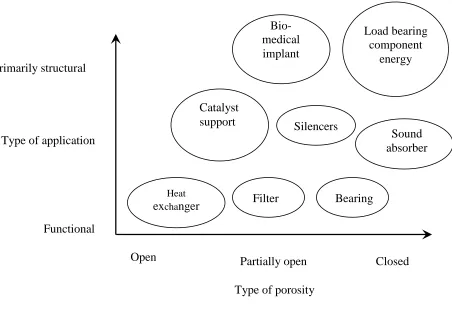
applications, closed cells are required. The application of cellular materials is classified in
accordance with the extent of connectivity required. Additionally, the applications are
also classified depending on whether they are primarily structural or functional, as
illustrated in Figure 2.4.
Cellular materials have many applications, such as in cooling machines, heat exchangers,
filtration, the transferring and storage of liquids, the support of catalysts, fluid flow
control, silencers, flame arresters, battery electrodes, water purification, electrochemical Functional
Type of application
Figure 2.4. Classification of application of cellular materials (Banhart, 2001). Primarily structural
Open Partially open Closed
Type of porosity Heat
exchanger Filter Bearing
Catalyst
support Silencers
Sound absorber
Bio-medical implant
Load bearing component
[image:39.612.111.563.256.569.2]19
and acoustic control (Banhart, 2001). For example, the radial heating element in an air
heater is often made from porous Fe-Cr-Al foam (Cookson et al., 2006). In addition,
Schwartz et al. (1998) reported that the replacement of honeycomb structures with an
aluminium foam sheet enables high performance at low cost in aerospace applications.
2.1.2 Types of stochastic foams
Open-cell foams are three-dimensional cellular materials. These types of foams are made
of cells with edges connected through open faces. The resulting foam is designated as
being an open-cell foam, as shown in Figure 2.5.
Figure 2.5. Open-cell aluminium metal foam (Chou and Song, 2002).
Closed-cell foams are three-dimensional cellular materials, in which the faces of the cells
are in solid form, arranged in such a way that each cell is sealed off from its neighbours.
20
in Figure 2.6. It has been noted that closed-cell foams provide a greater stability and
[image:41.612.218.438.143.346.2]strength compared with open-cell foams (Malekjafarian and Sadrnezhaad, 2012).
Figure 2.6. Closed-cell aluminium metal foam (Miyoshi et al., 1999). 2.1.3 Cell structures
The structures of the cells in a cellular solid material can vary. The structures can be
perfectly organised, as in a honeycomb structure, or they can be organised in a disordered
manner, such as in three-dimensional cellular solids materials, e.g. foams. The geometry
of the cells refers to their shape and size. The majority of honeycomb types have a
hexagonal shape. Therefore, the edge connectivity of such types of cell is six.
Alternatively, honeycombs can have square or triangular cells, with an edge connectivity
of four or three. Additionally, a random honeycomb structure has different sized cells.
They can either be small, with as few as three sides, or as many as nine sides of
21
The study of the geometry of three-dimensional cellular solids is more difficult than that
of honeycomb cellular solids. In 1873, Plateau identified that, with this type of cell shape,
it is possible to partition the space into an array of cells. Recently, computer modelling
has been used to identify the unit cells in foams. In 1995, Weaire and Phelan (Phelan et
al., 1995) identify the unit cells in a specified area per unit volume, as shown in Figure
[image:42.612.276.421.257.387.2]2.7.
Figure 2.7. Eight cells, forming a fundamental unit of a Weaire-Phelan foam (Phelan et al., 1995).
It has been determined that the face corrugations and the face curvature of foam cells can
substantially reduce the peak stress and the modulus of the metal foam (Simone and
Gibson, 1998). Additionally, variations in the thickness of the cell walls, wavy distortion
of the cell walls and non-uniformity in the shape of the cells have a substantial impact on
the mechanical properties of cellular solids (Grenestedt, 1998). It was concluded that
planar cell walls have a higher stiffness than curved and serrated cells (Sugimura et al.,
22 2.1.4 Characterisation of cellular materials
In order to characterise a cellular material, there is a need for a description of its cell type
(closed or open), its relative density, as well as the mean cell diameter (Gibson and
Ashby, 1999). Cellular materials can be characterised using many parameterss, such as
the mean diameter of the cell, the raw material that constitutes the cells, its shape, size
and its porosity and relative density (Wei et al., 2012). The constituents can be analyzed
with the help of scanning electron microscopy (SEM), optical microscopy and X-ray
tomography. The simplest method for measuring cell relative density or porosity is to
measure the weight, assuming that the sample is of a pre-known volume (Gibson and
Ashby, 1999). Furthermore, such foams can be characterised by their cell topology (open
cells and closed cells). Characterisation of metal foams can be undertaken with the help
of optical microscopy, provided that it is completely filled by an opaque epoxy before
being polished. SEM is the most useful technique for characterising open-celled foams,
whereas X-ray tomography is a useful technique for investigating the deformation modes
in cellular solids (Ashby et al., 2000). The tomography technique is dependent on the low
X-ray absorption characterisations of these materials, and it is a good technique to study
dense and large specimens. Another benefit of tomography is that the deformation modes
in the sample can be analyzed and monitored in a non-destructive manner (Maire et al.,
2003).
The mechanical properties of cellular materials are different from those of solid materials,
due to differences in their microstructures (Banhart, 2001). This section describes the
23
A stress–strain curve can be used to determine the Young’s modulus, as well as the
values of plateau strength and densification strain. An example of a general stress–strain
curve for a cellular material under uni-axial compression is given in Figure 2.8. It shows
the densification regime, the plateau strength and linear elastic region of the foam.
Figure 2.8. An example of a stress–strain curve for an elastic-plastic foam (Gibson, 2000).
The stress–strain curve for metallic foams shows three regimes of behaviour from the
material. As can be observed in Figure 2.8, initially, the curve shows a linear dependence
of stress on strain. Such a dependency is governed by the strength of the cell walls and
the solid material. It is evident that the stiffness of the metallic foam increases with the
increasing strength or stiffness of the cell walls (Ashby et al., 2000). It has been reported
that the type and grade of the solid metallic alloy has a significant effect on the stiffness
of metal syntactic foam (Orbulov and Ginsztler, 2012). It has been shown that metallic
alloys with a higher yield strength offer a greater stiffness than other alloys. In this part of
24
modulus of foams is calculated from the linear elastic region of the stress–strain curve. It
is affected by the following parameters: cell wall bending, edge contraction, membrane
stretching and the enclosed gas pressure (Siu, 1999; Surace et al., 2009; Zhao et al.,
2005). The slope of the first loading region of the stress–strain curve is lower compared
to the unloading curve; this is due to localisation of plasticity in the sample as the old
yield point value is lower than the compressive strength of the metallic foam. This is
illustrated in Figure 2.9 (McCullough et al., 1999).
Figure 2.9. An example of a loading and unloading stress–strain curve for a cellular foam.
The unloading curve is therefore recommended for the measurement of Young’s modulus
(Gubicza et al., 1996). The second stage in the graph is a stress plateau, which shows the
collapse of the cell walls, where buckling, yielding and brittle crushing of the foam takes
place (Mondal et al., 2009). This stage starts when the material reaches its initial yield
point. The shape of the plateau regime depends on whether the foam has open or closed
cells. This stage continues until the cell walls have collapsed following the start of the Unloading modulus E*
25
densification regime, where the stress begins to increase rapidly (Montanini, 2005). In the
final stage, the densification strain depends on the porosity of the foam, because during
the densification strain the pore space has squeezed (Tao, 2010). When the strength of the
cell walls in an open cell foam exceeds the value of the fully plastic moment, it creates
plastic hinges, which is when the densification stage starts. Stretching and bending of the
cell walls then occurs during densification of the closed-cell foam. In addition to this, the
presence of fluid within the cells also has an impact on the densification of closed-cell
foams (Mills, 2007).
2.1.5 Energy absorption
Energy absorption is the capability of a material to convert kinetic energy into another
form of energy such as heat, viscosity, visco-elasticity and visco-plasticity or even
friction. The kinetic energy should be less than the maximum limit of energy absorption
of the material in order to keep the object safe. Cellular materials typically have a good
capability for energy absorption.
The two most significant parameters for porous materials in terms of energy absorption
are densification strain and plateau strength (Sun and Zhao, 2003). The energy-absorbing
capability of the material is measured by the length and height of the flat part of the
stress–strain curve. The region below the plateau of the stress–strain curve represents the
energy per unit volume that can be absorbed (Iannace et al., 2001). This is illustrated in
Figure 2.10. When all the pores of the cells are closed, plastic deformation starts and the
stress becomes equal to the plateau strength. The composition and type of the matrix
26
Figure 2.10. Stress–strain curve for an energy absorbing material (ERG, Aerospace Corporation, 2011).
Foams have the capability to absorb kinetic energy more efficiently than their solid
counterparts (Gibson and Ashby, 1999). It is also noted that the energy-absorbing
capability of a foam depends on its porosity. In turn, the porosity controls the capability
of the material to obtain the maximum densification strain. In addition, the plateau stress
also depends on the porosity of the foam (Schneider et al., 1998). When the porosity of
the foam increases, the plateau stress decreases. Consequently, the level of energy
absorption is proportional to the porosity and the plateau stress (Sahu et al., 2013). On the
other hand, the plateau stress is inversely proportional to the porosity. From the literature,
it is concluded that energy absorption in a foam material can be maximised through a
27 2.1.6 Applications of cellular metallic materials
Metallic cellular materials are used in a wide range of applications, including the
automotive industry, as shown in Figure 2.11, lightweight construction, the aerospace
industry, the building industry, the railway industry, machine construction, sporting
equipment and the biomedical industry. The industries in which they have found
functional applications include the storage of liquids, the transfer of liquids, sparkers,
battery electrodes, water purification, fluid flow control, acoustic control, heat
exchangers as shown in Figure 2.12, cooling machines, supports for catalysts, flame
[image:48.612.162.497.355.558.2]arresters, electrochemical applications, silencers and filtration and separation.
28
Figure 2.12. Metal foams in heat exchanger applications (Fraunhofer, 2008).
2.2 Metal matrix syntactic foams
Metal matrix syntactic foams are composite materials that consist of a matrix that
incorporates porous or hollow ceramic particles (Zhao, 2011). This type of foam is a new
classification of material that can be produced using several metals matrices and ceramic
micro-spheres.
Matrix syntactic foam is a light material, which has a high energy absorption capacity
(Castro and Nutt, 2012). Researchers who have studied metal matrix syntactic foams
have focused particularly on the compressive behaviour and fabrication of these materials
(Orbulove and Majlinger, 2012). The most frequently used method for manufacturing
metal matrix syntactic foams is melt infiltration (Zhao, 2013). With this method, molten
metal is pressure-infiltrated into ceramic micro-spheres. However metal matrix syntactic
foams tend to deform under compression in a brittle mode, failing either by cracking or
29
The brittle deformation can lead to a significant reduction in plateau strength and energy
absorption.
In comparison with fully-dense alloys and metals, metal matrix foams show a high
specific stiffness, a low density, a mechanical damping capacity and a high energy
absorption capacity. Additionally, their closed-cell geometry is appealing due to the
insulating and mechanical properties it conveys to the foam (Balch et al., 2005).
2.2.1 Fabrication process
Most metal matrices in these matrix syntactic foams will be comprised of low density
materials, such as aluminium, magnesium and titanium. Three types of ceramic
micro-spheres have been used to fabricate metal matrix syntactic foams. These are amorphous
silica, Al2O3 spheres, ceramic spheres of crystalline mullite and steel spheres (Zhao et al.,
2008). There are three main methods for fabricating metal matrix syntactic foams via a
liquid state infiltration process, which are as follows:
Stir casting and spray process
Solid state processes
Deposition processes
In stir casting, metal matrix syntactic foams are fabricated by mixing a liquid metal
matrix with the ceramic particles, followed by casting (Rohatgi et al., 2011). This method
is extremely simple and less costly, but can lead to an inhomogeneous structure. The
technique of stir casting is commonly used for the manufacturing of metal matrix
composites (Sable and Deshmukh, 2012). In the stir casting method, the ceramic particle
volume fraction can be adjusted in an easy manner. However, this method also has a few
30
particles in a proper manner and consequently these particles start clustering (Sharma
et.al., 2011). As a result of this, the particles float to the top of the molten metals, as they
are lighter. These two disadvantages cause the ceramic particles to have poor dispersion
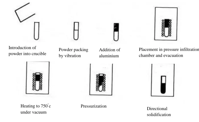
in the liquid metal and a resulting inhomogeneous structure (Zhao & Tao, 2009). In
infiltration casting, the metal matrix is placed above the ceramic spheres and is pressed in
order to infiltrate the ceramic sphere, where it is solidified to yield a metal matrix
syntactic foam (Orbulov, 2013). This is shown in Figure 2.13. Infiltration casting can be
carried out using gas pressure or die casting. This method offers the advantage that the
matrix and the ceramic micro-spheres are well bonded and the micro-spheres are usually
[image:51.612.156.506.344.559.2]distributed uniformly.
Figure 2.13. Various steps in the infiltration casting method (Evans et al., 2003). With the spray deposition method, there are only two ways to fabricate the metal matrix
syntactic foam. Either cold metal is continuously fed into a fast heat injection zone, or a
droplet stream is used, which is yielded from a molten bath (Clyne, 2001). Powder packing
by vibration
Placement in pressure infiltration chamber and evacuation
Pressurization
Directional solidification Introduction of
powder into crucible Addition of aluminium
31 2.2.2 Porosity
There are two classifications of porosity, namely, open or closed. Classification as open
or closed porosity depends on the ratio of void space volume to bulk volume (Cebon et
al., 2001). The porosity of foam depends on the shape and size of the pores. The strength
of the micro-spheres in a syntactic foam can be altered by varying the radius or the wall
thickness of the micro-spheres (Kiser et al., 1999).
The parameter that has the most significant effect on the porosity of a metal matrix
syntactic foam is the porosity of the ceramic micro-spheres. Ceramic sphere porosity can
be calculated using the following equation:
(2.1)
The term indicates the porosity of the ceramic micro-sphere, ρs is the effective density
and ρo is the micro-sphere solid part density. Therefore, the porosity of a metal matrix
syntactic foam can be calculated using the following formula:
(2.2)
where is the potential porosity of the syntactic foam and fal is the volume fraction of
the metal matrix. Zhang and Zhao (2007) developed a general formula that has been used
to calculate the porosity of metallic syntactic foam for all types of spheres. The formula is
as follows:
32
where ρm is the density of metal matrix present and ρƒ is the density of the syntactic foam.
Kiser et al. (1999) reported that the thickness and radius of the shells of the hollow
spheres control the composite porosity of a metal matrix syntactic foam.
It has been reported that compressive failure in a metal matrix syntactic foam is affected
by the volume fraction of ceramic micro-spheres. High volumes of metal matrix cause
ductile failure in the form of collapse of the material (Tao and Zhao, 2009). In contrast,
low volumes of metal matrix tend to lead to brittle failure, in the form of shear. The
failure behaviour of metal matrix syntactic foams is different from an ordinary foam, due
to its composition (Neville and Rabiei, 2008).
There are conflicting reports in the literature on the relationship between failure type and
cell size in metallic syntactic foams. For example, Kiser et al. (1999) found that syntactic
foam metal matrices with low values of the wall thickness to the radius ratio (t/r) failed
due to brittle behaviour, while those with higher ratio values experienced ductile failure
in the form of crushing or collapse. Multiple studies have reported that metal matrix
syntactic foams with low t/r ratio values failed due to their ductile properties and were
crushed or collapsed, while those with higher values failed due to brittle behaviour
leading to shearing (Gupta and Woldesenbet, 2004; Wu et al., 2007). Therefore, in
general, it may be concluded from the present literature review that the ratio of (t/r) is a
factor that affects the compressive failure of metal matrix syntactic foams.
2.2.3 Density
Rohatgi et al. (2011) was found that the higher density of syntactic foams have a higher
33
syntactic foams could be used to replace their matrix alloys in load bearing applications,
which could result in weight saving.
Moreover, it was revealed that the foams with monomodal ceramic microspheres have a
similar density and porosity due to the volume fraction of ceramic microspheres in the
foams while, the foams with bimodal ceramic microspheres have lower densities and
higher porosities due to the increases of the volume fraction of ceramic microspheres in
the foams (Tao et al., 2009).
Furthermore, it was found that the plateau stress increases with the increasing density of
[image:54.612.158.516.360.591.2]the aluminium matrix syntactic foams, as shown in Figure 2.14
Figure 2.14. Variation in plateau stress with density of the syntactic foams (Rohatgi et al.,