Commission of the European Communities
nuclear science
and technology
The Community's
research and development programme
Commission of the European Communities
nuclear science
and technology
The Community's
research and development programme
on decommissioning of nuclear installations
Third annual progress report 1987
Directorate-General
Science, Research and Development
Published by the
COMMISSION OF THE EUROPEAN COMMUNITIES Directorate-General
Telecommunications, Information Industries and Innovation Bâtiment Jean Monnet
LUXEMBOURG
LEGAL NOTICE
Neither the Commission of the European Communities nor any person acting on behalf of the Commission is responsible for the use which might be made of the
following information
Cataloguing data can be found at the end of this publication
Luxembourg: Office for Official Publications of the European Communities, 1988 ISBN 92-825-8899-8 Catalogue number: CD-NA-11715-EN-C
FOREWORD
This Ì3 the third Annual Progress Report of the European Community's 1984-88 programme of research on the decommissioning of nuclear installa-tions. It covers the year 1987 and follows the 1985 and 1986 Reports 11,21.
The Council of the European Communities adopted the programme in January 1984 /3/, considering: "Certain parts of nuclear installations inevitably become radioactive during operation; it is therefore essential to find effective solutions which are capable of ensuring the safety and protection of both mankind and the environment against the potential hazards involved in the decommissioning of these installations".
Also, the Council recognized that the 1979-83 programme of research on the decommissioning of nuclear power plants, of which the current pro-gramme is a follow-up, "has yielded positive results and opened up encouraging prospects". The main publications relating to the results of this first programme are listed in Annex I.
The 1984-88 programme has the following contents:
A. Research and development projects concerning the following subjects: Project N° 1: Long-term integrity of building and systems;
Project N° 2: Decontamination for decommissioning purposes; Project N° 3: Dismantling techniques;
Project Ne 4: Treatment of specific waste materials: steel, concrete
and graphite;
Project N° 5: Large containers for radioactive waste produced in the dismantling of nuclear installations;
Project N° 6: Estimation of the quantities of radioactive wastes arising from the decommissioning of nuclear installa-tions in the Community;
Project N° 7: Influence of installation design features on decommis-sioning.
B. Identification of guiding principles, namely:
- certain guiding principles in the design and operation of nuclear installations with a view to simplifying their subsequent decommis-sioning,
- guiding principles in the decommissioning of nuclear installations which could form the initial elements of a Community policy in this
field.
C. Testing of new techniques under real conditions, within the framework of large-scale decommissioning operations undertaken in Member States. The research is carried out by public organisations and private firms in the Community under cost-sharing contracts with the Commission of the European Communities. The Commission budget planned for this five-year programme amounts to 12.1 million ECU. The main publications relating to the results of this programme are listed in Annex II.
The Commission is responsible for managing the programme and is assisted in this task by the Management and Coordination Advisory Commit-tee "Nuclear fission energy - Fuel cycle/processing and storage of waste" (see Annex III).
The present report describes the objectives, scope and work program me of each research contract concluded, as well as the progress of work achieved and the results obtained in 1987.
For each contract, the Paragraph "C. Progress of Work and Obtained Results" has been prepared by the contractor, under the responsibility of the Project Leader. The Commission wishes to express its gratitude to all scientists of the contractors who have contributed to this report.
The Commission staff having edited the report are: E. Skupinski, R. Bisci and K. Pflugrad.
Β. Huber
Head of the Programme
References
/l/ "The Community's research and development programme on decommission ing of nuclear installations. First annual progress report (year 1985)". EUR 10740, 1986.
¡21 "The Community's research and development programme on decommission ing of nuclear installations. Second annual progress report (year 1986)". EUR 11112, 1987.
131 Council Decision of 31 January 1984 adopting a research programme concerning the decommissioning of nuclear installations. OJ N° L 36, 8.2.1984, p. 23.
CONTENTS
Page
1. PROJECT N° 1 : LONG-TERM INTEGRITY OF BUILDINGS AND SYSTEMS 1 1.1. Deterioration assessment of nuclear power station buildings. 2
1.2. Long-term stability and leak-tightness of reactor
containments 7 1.3. Consequences of suppression of negative pressure in the
KW-Lingen containment 11 2. PROJECT N° 2: DECONTAMINATION FOR DECOMMISSIONING PURPOSES 17
2.1. Complete decontamination of a primary steam piping of the
Lingen BWR 18 2.2. Aggressive chemical decontamination tests on valves from the
Garigliano BWR 19 2.3. Decontamination using chemical gels, electrolytical swab and
jet, abrasives 24 2.4. Development of an easy-to-process electrolyte for
decontami-nation by electropolishing 27 2.5. Optimisation of filtering systems for various concrete
decontamination techniques 33 2.6. Economic comparison of decontamination and direct melting
with a view to recycling of scrap 38 2.7. Remote electrochemical decontamination for hot cell
applications 39 2.8. Decontamination with pasty pickling agents forming a
strippable foil 44 2.9. Rack-torch unit for remote decontamination of concrete 49
2.10. Feasibility of concrete decontamination using a
plasma-augmented burner 54 2.11. Closed electropolishing system for decontamination of
underwater surfaces 60 2.12. Development of vibratory decontamination with abrasives .... 65
3. PROJECT N° 3 : DISMANTLING TECHNIQUES 69 3.1. Ventilation and filtration techniques for thermal cutting
operations 70 3.2. Prefiltering devices for gaseous effluents from dismantling
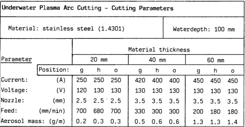
operations 76 3.3. Dross and ultrafine particulate formation in underwater
plasma-arc cutting 82 3.4. In-situ arc-saw cutting of heat exchanger tubes and of pipes
from the inside 88 3.5. Electrochemical technique for the segmenting of activated
steel components 93 3.6. Explosive techniques for the dismantling of biological
shield structures 94 3.7. Explosive techniques for dismantling of activated concrete
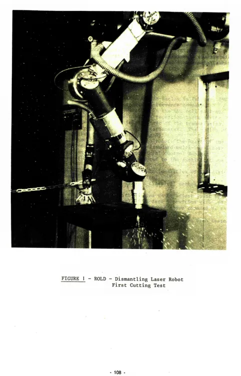
structures 100 3.8. Prototype system for remote laser cutting of radioactive
structures 105 3.9. Investigations of applications of laser cutting in
decommissioning 109 3.10. Spreading and filtering of radioactive by-products of
under-water segmenting 114
-3.11. Development of a prototype system for remote underwater
plasma-arc cutting 120 3.12. Adaptation of a robot and tools for dismantling of a
gas-cooled reactor 126 3.13. Remote measuring and control systems for underwater cutting
of radioactive components 131 3.14. Removal of concrete layers from biological shields by
microwaves 137 3.15. Adaptation of an existing air-tight and modular workshop
for remote operation 143 3.16. Adaptation of abrasive water jet to cutting of radioactive
steel and concrete 149 3.17. Development of abrasive water jet for submerged cutting of
steel 155
4. PROJECT N° 4: TREATMENT OF SPECIFIC WASTE MATERIALS: STEEL,
CONCRETE AND GRAPHITE 159 4.1. Melting/refining of contaminated steel scrap from
decommissioning 160 4.2. Melting of radioactive metal scrap from nuclear
installations 163 4.3. Separation of stainless steel constituents using transport
in the vapour phase 169 4.4. Immobilisation of contamination of large waste units by
polymer coating 170 4.5. Treatment of active concrete dust by slurry setting method.. 172
4.6. Investigations into the melting of radioactive metal waste
in a controlled area 174 4.7. Behaviour of actinides and other radionuclides that are
difficult to measure, in melting of steel 176 4.8. Conditioning and disposal of radioactive graphite bricks
from reactor decommissioning 181 4.9. Separation of contaminated cement-stone and
non-contaminated concrete aggregates 184 5. PROJECT N° 5: LARGE TRANSPORT CONTAINERS FOR RADIOACTIVE WASTE
PRODUCED IN THE DISMANTLING OF NUCLEAR INSTALLATIONS 188 5.1. Design and evaluation of large containers for reactor
decommissioning waste 189 5.2. Large waste containers made of fibre-reinforced cement 193
5.3. Large waste containers cast of low-level radioactive metal
scrap 196 6. PROJECT N° 6: ESTIMATION OF THE QUANTITIES OF RADIOACTIVE WASTE
ARISING FROM THE DECOMMISSIONING OF NUCLEAR INSTALLATIONS IN THE
COMMUNITY 203 6.1. The assessment of low-level contamination from
gamma-emit-ting radionuclides 204 6.2. Development of methods to establish the curie content of
radioactive waste from decommissioning 207 6.3. Systems for contamination measurements on curved surfaces... 211
6.4. Optimisation of measurement techniques for very low-level
radioactive material 214 6.5. Monitoring gamma radioactivity over large land areas using
portable equipment 219 6.6. Radioactive wastes arising from the dismantling of a
commercial Fast Breeder Reactor 222
-6.7. Methodology for assessing suitable systems for management
of reactor decommissioning wastes 228 6.8. Radiological evaluation of releasing very low-level
radioactive copper and aluminium 232 7. PROJECT N° 7: INFLUENCE OF NUCLEAR INSTALLATION DESIGN FEATURES ON
DECOMMISSIONING 234 7.1. Decontamination and remote dismantling tests in the ITREC
reprocessing pilot plant 235 7.2. Testing of cobalt-free valve seatings using a special test
loop 236 7.3. Pre-stressed concrete reactor vessel with built-in planes
of weakness 241 7.4. In-situ sealing of concrete surface by organic impregnation
and polymerisation 247 7.5. Influence of design features on decommissioning of a large
Fast Breeder Reactor 251 8. SECTION C: TESTING OF NEW TECHNIQUES UNDER REAL CONDITIONS 257
8.1. Dismantling and decontamination of a feedwater preheater
tube bundle of' Garigliano BWR 258 8.2. Conditioning, transport and dismantling of very large
plutonium glove-boxes 265 8.3. Large-scale application of segmenting and decontamination
techniques 266 8.4. Development of techniques to dispose of the Windscale AGR
heat exchangers 272 8.5. Pilot decommissioning of a mixed-oxide fuel fabrication
facility 278 8.6. Testing of new techniques in decommissioning of a fuel
(U, Th) fabrication plant 283 8.7. Decontamination and dismantling of the PIVER prototype
vitrification facility 286 8.8. Dismantling, partly in-situ, of a glove-box structure of a
mixed-oxide fuel plant 289 8.9. Melting of radioactive metal scrap from the KRB-A plant .... 290
8.10. Volume and plutonium inventories before and after
disman-tling of a mixed-oxide fuel plant 295 8.11. Decontamination, before dismantling, of the primary coolant
system of the RAPSODIE FBR 298 8.12. Automated measuring system for waste from dismantling of
the KKN plant, to be released 302 X X
X
ANNEX I LIST OF PUBLICATIONS RELATING TO THE RESULTS OF THE 1979-83 PROGRAMME ON THE DECOMMISSIONING OF NUCLEAR POWER PLANTS ... 307 ANNEX II LIST OF PUBLICATIONS RELATING TO THE RESULTS OF THE 1984-88
PROGRAMME ON THE DECOMMISSIONING OF NUCLEAR INSTALLATIONS... 310 ANNEX III MEMBERS OF THE MANAGEMENT AND COORDINATION ADVISORY
COMMITTEE "NUCLEAR FISSION ENERGY - FUEL CYCLE/PROCESSING
AND STORAGE OF WASTE" 311
1. PROJECT N"l:
LONG-TERM INTEGRITY OF BUILDINGS AND SYSTEMS A. Objective
It has been proposed that the dismantling of nuclear installations be delayed for periods ranging from several decades to about a hundred years. Thereupon, the radioactivity having largely died away, dismantling would be easier and the radiation exposure of the dismantling personnel would be less. The objective of this project is to determine the measures required for maintaining shut-down plants in a safe condition and to assess the radiological consequences and costs.
B. Research performed under the 1979-83 programme
The work performed under the previous programme relates mainly to the following aspects:
- mode and pace of degradation of various materials as they exist in nuclear power plants;
- measures for maintaining plants in a safe condition and for keeping the necessary ancillary systems operable;
- monitoring and inspection procedures;
radiological consequences and costs of maintaining the plants. C. 1984-88 programme
The work performed under the first five-year programme should be comple-mented by further tests and the study of control methods relating to the aging of relevant plant materials and by exploitation of additional experience with shut-down nuclear installations.
D. Programme implementation
1.1. Deterioration Assessment of Nuclear Power Station Buildings Contractor: Taylor Woodrow Construction Ltd, Southall, UK Contract N°: FI1D-0030
Working Period: April 1986 - December 1988 Project Leader: I. LI. Davies
A. Objectives and Scope
The objective of this research is to study the long-term performance of structures comprising nuclear power plants. The time period of inter-est for this study is 140 years (this figure is based on maximum periods of 40 years for operation and 100 years of storage). Particular attention will be given to those parts of the plant for which leak tightness and structural integrity are required, both during operation and for long periods after final shutdown.
This research will be executed in close co-operation with Zerna, Schnellenbach und Partner GmbH (see Par. 1.2.).
The specific aim of this research is to predict future deterioration of nuclear power station buildings, due to corrosion of reinforcement and prestressing steel. The state and rate of degradation of existing build-ings will be assessed to provide qualitative data and to improve existing knowledge of the factors controlling the ageing process of nuclear plant buildings. Relevant plant materials will be identified and proposals made for monitoring procedures, preventive measures and recommendations for future designs.
Buildings to be investigated will be typical of power stations of the United Kingdom. However, the results will be applicable also to plants sited in other European Community countries due to the nature of
the specific problems posed. The survey of station buildings will be carried out on a range of nuclear power sites in the United Kingdom, selected to provide a range of exposure conditions, various degrees of deterioration and a range of concrete types. This survey will include the shut-down Gas-cooled Reactor stations of Chinon-Al and Marcoule-G2 in France.
B. Work Programme
B.1. Selection of sites and concrete types.
B.2. Literature survey including the assessment of the in-situ state of the concrete and steel and the determination of the causes for concrete deterioration and corrosion of steel.
B.3. In-situ testing of the materials, using non-destructive techniques, including the measurements of ultrasonic pulse velocity, rebar potential, concrete resistivity, etc.
B.4. Laboratory tests on samples removed from safe areas (concrete strength, depth of carbonation, water permeability, oxygen diffu-sion, etc.).
B.5. Use of the test results, to develop a computer program predicting rate of deterioration, onset and rate of corrosion, extent of cracking and spalling, damages, service life of the structure, etc. B.6. Recommendations for damage prediction and for reducing corrosion
rates.
C Progress of Work and Obtained Results Summary
Suitable sites for survey work are expected to be agreed with Central Electricity Generating Board (CEGB) shortly, and it is also now likely that the UK Atomic Energy Authority (UKAEA) site at Windscale will be available for survey work. A preliminary survey of the latter is due shortly, with the main survey commencing as soon as possible thereafter. Detailed plans of in-situ testing, samples to be taken, and sample testing have been prepared, subject to finalisation after preliminary surveys. Development of the predictive model continues, in anticipation of results from surveys and sample analysis.
Progress and Results
1. Selection of Sites and Concrete Types (Bl)
The research programme is based on surveys of existing nuclear power plants in the UK to provide quantitative data on the state and rate of degradation of ' the associated buildings. Constraints within the programme dictate that it is not practicable to survey all existing nuclear power stations in the UK, and therefore, to meet the objectives of this programme, stations surveyed should represent a wide range of environmental conditions for the materials sampled and tested. To improve the calibration process for the deterioration prediction package, the availability of previous survey data is also being considered in station selection, for example work carried out by the CEGB under the framework of the CEC's Phase 1 research programme on Decommissioning of Nuclear Power Plants /l/.
Discussions are currently in progress with the CEGB to identify suitable sites for the survey work and to agree on the programme of work for each site with the aim of commencing the surveys in February 1988. It has also emerged that the UKAEA site at Windscale should be available for survey work. A preliminary survey for familiarisation and planning of survey areas and sampling locations is to be undertaken 28, 29 January 88; dates for the main survey will also be established on that occasion.
2. Literature Survey and Deterioration Prediction (B2, B6)
In freshly placed concrete, reinforcement steel is protected by the high alkalinity of the surrounding cement paste, which causes the steel to be passivated. With time, however, the alkanity of the surrounding cement paste may be reduced by the neutralising effects of carbon dioxide diffusion into the concrete from the atmosphere (carbonation). Furthermore the ingress of corrosive salts, primarily chlorides, can destroy passivation resulting in corrosion even under the highly alkaline environment of steel in concrete.
The rate of progression of the de-passivation front through the reinforcement cover is slow. The time taken for the depth of penetration of chlorides or carbonation to become equal to the depth of cover to the reinforcement is known as the initiation time (Tn).
-Once corrosion has been initiated, the rate at which the corrosion progresses is determined by both the rate of the anodic and cathodic reactions and the resistivity of concrete and the availability of moisture and oxygen. Assuming an adequate supply of oxygen and water, corrosion proceeds for a second period (Ti) until the amount of corrosion products formed is sufficient to cause cracking and eventually spalling of the concrete.
The programme is currently concentrating on the period leading to the initiation of corrosion, which is the key to the life prediction process. The two main mechanisms, mentioned above, by which corrosion is initiated are being pursued, with the aim of producing a more rigorous model,for estimating the time to the onset of corrosion, based on the following factors,
- rate of progress of the carbonation front
- rate of chloride diffusion into the concrete and to reach a threshold level at the steel location
- definition of the threshold levels
- depths and variations in depth of concrete cover to the steel 3. In-Situ Testing. Laboratory Tests on Samples, and Results Analysis
(B3, B4, B5)
To predict the future deterioration of the buildings concerned, the processes to be modelled require data to be collected in surveys; in the following sections, the work planned is outlined. Survey areas will be defined based on initial site visits, layouts of structures, and reviews of any previous similar work. It is planned that all the tests should be carried out both on bioshield/pcpv concrete structures and on non-critical structures of similar concretes, with the exception of core sampling which would only be carried out on
'similar' concretes. 3.1 Environment
Environmental variables such as temperature, relative humidity, CO2 content of air, chloride content of air, rainfall, all affect the possible deterioration processes and should therefore be measured, (except where suitable information is available from records). To compare the deterioration and concrete performance of the bioshields/pcpv's with those of the reactor hall concrete or other concrete structures, it will be necessary to monitor the above environmental factors both inside and outside the reactor hall, so that the effect of different environments can be included in the overall assessment. Deterioration of the building fabric currently protecting the bioshield/pcpv concrete could worsen the internal environment, thereby increasing the risk of concrete deterioration. Therefore a visual inspection of typical components will be carried out with further test work if necessary, to identify the potential
'weak-link' components requiring routine checks or maintenance.
3.2 Corrosion Activation
The main variables to be measured are as follows:
3.2.1 Depth of carbonation: measured by drilling or otherwise forming a shallow hole in the concrete surface and spraying a fresh-fractured surface with a chemical indicator solution. The variability of carbonation depth will be measured by making measurements at as many points as possible - at least 25 points being desirable (and preferably more), at randomly chosen locations, whilst taking account of any major environmental variations noted. Wherever possible carbonation depth measurements will be at holes made for other purposes (eg chloride drillings, reinforcement connections, core holes, etc). 3.2.2 Chloride content profile: Measured by incrementally collecting
dust drillings, for subsequent chemical analysis. Since chloride ingress is unlikely to be significant so far in concrete not exposed to sea-spray, in general only a small number of locations would be checked (say 5 or 6). For marine exposure, however, more ' results are necessary, to measure the variability
(as for carbonation). Measurement of chloride diffusion coefficients on cores from similar concretes is also necessary. 3.2.3 Depth of Cover to Reinforcement: Measured by covermeter with
comparative checks from direct measurement of 'as-built' cover after exposing short lengths of reinforcement. The distribution of cover should preferably be measured for each reinforcement bar type/location, again by taking a large number of readings randomly located. (Non-destructive apart from comparison points). Reinforcement layouts and sizes will be pre-checked from drawings if available.
3.2.4 Reinforcement Potentials: Survey by reinforcement potential measurement (potential wheel) to estimate present extent of corrosion activation. Potentials assessment criteria will be checked by exposing reinforcement, in areas of high, low and typical potential. Electrical connection to reinforcement is required, together with checks of electrical continuity over large areas or between different elements. (Non-destructive apart from assessment criteria checks & electrical connections). 3.3 Corrosion Propagation
There are two main aspects of corrosion propagation which together imply the time from corrosion activation to damage occurrence:
corrosion rate, R
amount of corrosion, M, the formation of which on a steel bar causes a predefined level of damage to occur.
Therefore the time from activation to damage - M/R
The corrosion rate, R will be estimated from a combination of survey work (linear polarisation, concrete resistivity, initial surface
-absorption tests), and laboratory tests on samples (water sorptivity, oxygen diffusivity, moisture content).
The amount of corrosion on a bar, M, which results in damage is estimated from modelling and previous research work on the tolerable stresses, together with information collected during surveys (reinforcement diameter, cover, spacing; current extent of corrosion on reinforcement).
References
i.2. Long-term Stability and Leak Tightness of Reactor Containments Contractor : Zerna, Schneilenbacb ur.d Partner GmbH, Bochum, Germany. Contract Nr': FI1D-0031
Working Period: April 1986 - December 1988 Project Leader: R. Oberpichler
A. Objectives and Scope
The objective of this research is to study the long-term performance of structures comprising nuclear power plants. The time period of inte rest for this study is 140 years (this figure is based on maximum periods of 40 years for operation and 100 years of storage). Particular attention will be given to those parts of the plant for which leak tightness and structural integrity are required, bcth during operation and for long periods after final shutdown.
This research will be executed in close co-operation with Taylor Woodrow Construction Ltd (see Par. 1.1.).
The specific aim of this research is to investigate the behaviour of complex composite structures, taking as a basis the long-term behaviour of materials. The possible Fusceptibility to long-term damage will also be assessed, and the ar'eas most prone to such damage will be identified. Further consideration will be given to the possible interaction between sealing steel component.'; (steel containments, steel liners) and load bearing concrete structures.
This building survey will be carried out on structural elements of actual PWR stations (e.g. Emsland-Lingen) and BWR stations (e.g. Gundrem-mingen Β and C) . Consideration will be given to the validity of the investigations for relevant structures of other commercial nuclear power plants in the European Community. This investigation will include the shut-down BWR station of Garigliano in Italy.
B. Work Programme
B. 1. Investigation on reinforced concrete and prestressed concrete structures.
B.l.l. Selection of structural elemerts considered important with regard to the integrity of long-term containment.
B.1.2. Literature study on material behaviour covering long-terra proper ties.
B.J.3. Analysis of the long-term behaviour of the selected structural elements.
B.2. Investigation of steel containments
B.2.1. Selection of elements susceptible to damage, in particular plastic sealings with concrete and steel.
B.2.2. Assessment of damage (state of material, types of corrosion, formation of condensed mei sture, permeability of the concrete, etc.)
B.2.3. Optimisation of ultrasonic testing techniques (angular sound, weakening, creep wave, etc.) and application of the selected
techniques to decommissioned Kiederaichbach and Gundremmingen I nuclear power plants.
C. Progress of Work and Obtained Results Summary
During 1987, the following aims of the research programme were developed:
- special structural elements were selected in accordance with their relevance and various test methods were discussed, in order to analyse the long-term behaviour (B.I.3.);
- an extensive study concerning the corrosion mechanism was performed (B.2.2.),
- a test programme on the long-term behaviour of plastic seals was drawn up (B.2.1. ) ,
- ultrasonic tests were carried out in order to detect corrosion in inaccessible areas (B.2.3.).
Progress and Results
1. Analysis of the long-term behaviour of the selected structural ele-ments (B.1.3.)
Structural elements were selected concerning their relevance for the functioning and long-term stability of the reactor building. A further criterion for the selection was the range of utilisation of materials already under dead load. For application on these main structural ele-ments, various test methods like monitoring procedures, especially non-destructive ones, were discussed. These test methods are for ins-tance:
- visual checjcs for gaining a rough survey over the actual state of all accessible areas,
- taking core samples for getting accurate measurements of the main accessible areas,
- ultrasonic pulse velocity (UPV) tests as one of the important non-des-tructive test methods which are still in development,
- and other non-destructive tests for checking the concrete cover, carbonation depth and chloride concentration.
Hereby the properties of concrete like strength, cracks, voids, alkalinity, concrete cover, etc., are of main interest. Concerning the reinforcement, the conditions for corrosion have to be established by test methods. No severe effects on the stability of the structural ele-ments are expected if the durability of anchorage eleele-ments or bearings will be less than the entire period preceding dismantling.
Generally, it is recommended for all inner structural elements and especially those which are located in inaccessible areas to maintain corrosion-delaying climatic conditions.
Regarding the monitoring procedures, the stability of the reference plants can be expected to continue at least 100 years after decommission-ing.
theore-tical corrosion models that describe the behaviour of the material? used under certain conditions ''e.g. corrosion medium).
The work found during searches of the literature on the behaviour of concrete steels or of reinforced concrete car: be applied only indirectly to the long-term corrosion behaviour of the containment and raist be adapted to take account of the specific circumstances.
The behaviour of the materiali; used was examined under the given corrosive conditions by means of theoretical corrosion models. As far ar the surface corrosion of unalloved c,teels and low-alloy steels in weakly
acid to weakly alkaline media is concerned, the: available data in the-literature indicate rates of about 0.09 to 0.3 mm/a. Data on the sion rate with ground craters *nd holes are not available for the corro-sion/chemical conditions in the containment. This is because the data frequently depend on indefinable local circumstances, such a;; heteroge-neity of the surface, porousness of rustproof coatings, growing concen-tration of chlorides, etc., and thus, cannot be recorded by their verv nature. Under the prevailing circumstances, the conditions for stress corrosion cracking do not exist. During the further investigations, proposals will be made for prevention of corrosion damage.
3. Long-term behaviour óf plastic seals (B.2.1.)
After establishing the concept, the requirements of plastic seals were determined; they result from the operating conditions of the P*-rR
plants presently being constructed. In addition, a test programme was drawn up with reference to ageing and time extrapolation.
The literature indicates that, as a matter of principle, the ageinp of silicones can be determined with the Arrhenius- ?nd Williams-Landl-Ferry-equations; this is to be proven by the; study. For that reason, 200 test pieces of silicone material were made in accordance with the proces-sing guidelines and the instructions for producing test pieces at one or
the convoy sites. These tests were expected to take 1.5 years.
These test pieces were installed in. r.pecial devices with 257 com-pression strain and stored in heating furnaces at 40, 60, 80 and 120 degrees. After 24, 72, 168, 336 and 67? hours, samples were taken and the residual compression strain values determined.
The curves show a steady increase of the residual compressi on strain and seem to have reached a maximum after about 14 days, since the value? decrease again slightly atter this period.
A first evaluation with an attempt to extrapolate- the results will be made after a storage period of about six months (mi.d-198S). Adhesive strength tests will also be carried out on the samples available by then and the results evaluated.
In the meantime, studies of the literature, i.e. specialised litera-ture on the ageing of silicone rubbers in particular are continuing.
4. Non-destructive tegts (B.2.3.)
Non-destructive tests, using ultrasonic methods, are to prove corrosion damage in inaccessible areas between reactor containment and reinforced concrete.
Tests on a test piece with *-ke ground craters and tests on the reactor containment of a nuclear power plant with corrosion damage aired at determining suitable.· test heads i or detecting these types of defect. As a result of the coating or the surface roughness of the reactor containment, the best results were obtained with a 45° angle test head.
The test results showed that the sensitivity difference of the echo height from the deflection areas and the individual indications of the corrosion scars is max. 6 dB. However, this is too little to prove corrosion with certainty.
Further tests and improved test methods aim at clarifying whether this signal-to-noise ratio can be improved.
1.3. Consequences of Suppression of Negative Pressure in the KW-Lingen Containment
Contractor:
Contract N°: Kernkraftwerk Lingen GmbH, Lingen, Germany FIlD-0032 Working Period: February 1987 - January 1989
Project Leader: W. Harbecke
A. Objectives and Scope
It is common practice to maintain a negative pressure in the con-tainment of shut-down nuclear reactors in order to avoid a transfer of the remaining radioactivity to the outside.
The objective of the present contract is to assess, from the stand-point of radiation protection of the environment, the acceptability of suppressing the provided ventilation and, consequently, the negative pressure in the containment of the shut-down Lingen Boiling Water Reactor Plant. The use of the ventilation system would then be limited to casual drying and air-conditioning purposes.
The work is aimed at demonstrating that safe enclosure without negative containment pressure might be acceptable.
B. Work Programme
B.1. Inventory of the relevant plant characteristics and of the key issues to be considered.
B.2. Estimation of the activity release to be expected with shut-down ventilation system.
B.3. Design of an instrumentation system and a measurement programme for the control of the containment atmosphere.
B.4. Implementation of the measurement programme. B.5. Evaluation of the obtained results.
1.4 1.7 1.8
ElO E 9 E14 C. Progress of Work and Obtained Results
Summary
During this period, the inventory of the relevant plant characteris-tics and of the key issues to be considered, as well as the radioactive inventory of the safe enclosure (SE) were carried out. Up to mid-1987 the required instrumentation was installed and since July, the measured values were recorded. The status of the plant is as follows:
- no fissile material is in the plant;
all systems are drained and all drain-valves are open;
- the stored waste is mostly non-conditioned, so that the resins and ion-exchange powder are only drained and still in their storage tanks.
It is important to know that a small ventilation system is under operation. The system circulates a volume of 3,500 m3 of air per hour,
which is dried and a volume of 600 m3 per hour, which is filtered and
released through the stack. Progress and Results
1. Radioactivity inventory (B.l.)
The activity inventory was performed for the reactor and auxiliary buildings:
Inventory of the Inventory of the reactor building auxiliary building
(Bq) (Bq) Activated, material 8.2 E15
Contaminated surfaces inside systems 2.1 E13 Contaminated building surfaces 1.7 E 9 Stored waste 1.4 E12 2. Estimation of activity release (B.2.)
The airborne activity release will occur due to three effects: - temperature variations inside the SE: this effect can be neglected;
atmospheric pressure variations: this effect is very small, but it is calculated. The results are given in Table I;
- pressure differences caused by the wind: this gives the main effect and depends on the tightness of the plant. The leakage-rate as a function of pressure differences is evaluated and the strength of the wind as a function of time is measured. The leakage is calculated
twice :
. under the condition of a running off-air system (with an off-air rate of 600 m3/h and a negative pressure of 10 Pa);
. without the effect of negative pressure.
3. Implementation of the measurement programme (B.3.)
The measurement programme is fully under operation. However, due to the unusual weather conditions, some of the measured values are not representative. In addition, the plant itself reached the technical status of the SE in mid-1987 (shutdown of the original ventilation G3Tstem), but there was still some water in the plant. The results for the
second half year are as follows:
- The specific aerosol activity is in the order of 4x10 3 Bq/m3 (95%
Cs-137 and 5% Co-60). There are some differences between the different buildings. Probes were taken by filter sampling.
- The tritium activity measured in the condensate accumulated in the air-drying system is in the order of 1 MBq/m3. The tritium activity in
the air with a water content of 6 g/m3 is about 6 Bq/m3.
-- The radon activity, measured by the Karlsruhe Nuclear Research Centre, varies between 50 Bq/m3 in the auxiliary building and 200 Bq/m3 in the containment.
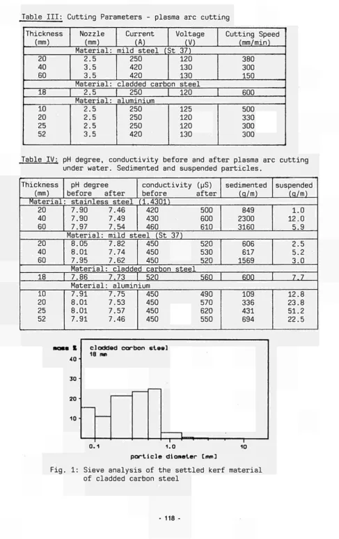
The temperature and the relative humidity of the air are measured in all three buildings (containment, angulun with connecting building and auxiliary building) in each case at the bottom, in the middle and at the top;
. the temperature variation is shown in Figure 1. (The figures are not typical due to the unusual weather during this winter);
. the relative humidity in the containment is given in Figure 2.
- The wind force is printed out continuously as a percentage of time for some ranges of velocity. An example is given in Figure 3.
- The leakage of the SE was measured by variation of the off-air rate. The results are pointed out in Figure 4. The leakage is a non-linear function of the pressure difference against the outside atmosphere. 4. Evaluation of the obtained results (B.5.)
It is too early for a final discussion of the results. Table II shows the calculated monthly leakages for the SE split into the leakage due to wind and atmospheric pressure drops. The calculated leakage and the measured tightness are the data for the complete area of the SE, i.e. the auxiliary building, the connecting building and the angulus. The leakage of the containment alone ought to be small against this.
One can notice that there is a factor of two between the leakage with and without a ventilation system.
The activity output due to the leakage is very small. Without a ventilation system, the aerosol output is higher by a factor of two, but the tritium output is lower by a factor of two than with a ventilation system. The reason for this is that the aerosols in the off-air system are reduced by means of a HEPA filter, i.e. by a factor of 1,000 or more; the tritium can only be reduced by drying up the air, i.e. by a factor of less than two. The results are shown in Tables III and IV.
Table I; Monthly leakages due to variations of atmospheric pressure
! ! Month ! July ! August ! September ! October ! November ! December ! Total: ι
Sum of pres sure drops (Pa) 75 67 73 55 93 79 Expansion of air volume (%) 7.5 6.7 7.3 5.5 9.3 7.9
Air expansion of ! containment
(m3) 5,042 4,504 4,908 3,698 6,252 5,311 29,716
Table II: Monthly leakages for the total area of the SE due to wind
! Month ! Leakage rate ! Total air exchange ! Leakage rate ! ! ! with ventilation ! with ventilation ! without ventilât. !
! ! (m3) ! (m3) ! (m3) !
! July ! 81,980 ! 513,980 ! 220,266 ! ! August ! 64,646 ! 496,646 ! 202,858 ! ! September ! 57,900 ! 489,900 ! 192,750 ! ! October ! 374,766 ! 806,766 ! 464,600 ! ! November ! 34,849 ! 466,849 ! 149,148 ! ! December ! 102,085 ! 534,085 ! 239,113 !
! Total: ! 716,226 ! 3308,226 ! 1468,735 !
Table III: Monthly aerosols activity output of SE total area (Bq)
! Month ! July ! August ! September ! October ! November ! December ! Total: Without venti-lation system 1,000 920 880 2,100 690 1,100 6,690 With ventilation by leakages 390 310 280 1,700 180 480 3,340 system via stack !
2 2 2 2 2 2 12 total ! 392 ! 312 ! 282 ! 1,702 ! 182 ! 482 ! 3,352 !
Table IV: Monthly tritium activity output of SE total area (MBq)
! ,, _, ! TT.^, . ! With ventilation system '.
! Month ! Without venti- ! ! ! ! lation system ! by leakages ! via stack ! total !
! July ! 1.8 ! 0.7 ! 3.5 ! 4.2 ! ! August ! 1.7 ! 0.5 ! 3.5 ! 4.0 ! ! September ! 1.6 ! 0.5 ! 3.5 ! 4.0 ! ! October ! 3.7 ! 3.0 ! 3.5 ! 6.5 ! ! November ! 1.2 ! 0.3 ! 3.5 ! 3 . 8 ! ! December ! 2.0 ! 0.8 ! 3.5 ! 4.3 !
! Total: ! 12.0 ! 5.8 ! 21.0 ! 26.8 !
[image:24.595.72.536.86.504.2]Reactor Building
r ^ e o o ^ o ^ - c v i K v - ^ m e o r ^ o o o i O ^ c v i K j - ^ i n c o r v o o c D O T - t M K i N N N H i * ) i o n n i o i i i o n i < ) < *t *t *t *t *r *t ■& ■* ·* o m io in
Week
Figure 1 : Evolution of the t e m p e r a t u r e
8 0
7 0
-K 60 ■
50 f
4 0 -/
l i l i l í
Reactor Building
\ / \ ν χ x ^ i—r
l I l 1 1 1 1 1 1 I 1 1 I I 1 1 1 1
H— lop
-Β— middle
-κ— bottom
Γ ^ ο ο σ > ο ^ - ο ν ΐ κ > · * ι Λ < ΰ ΐ ^ ο ο ο Ν θ · - ί ν ι Κ ) · < ι · ι η < ο ι ^ ο ο σ ι θ · - Γ Μ ΐ η
Week
Figure 2 : Evolution of the relative humidity
-Frequency (%)
65. Height of the measuring point
from the ground level: 15 m
o o
9.
o o
I. 2. 3. 5. 7. 9. ,2 Velocity (m/s)
Figure 3: Histogram of the wind velocity during December 1987
Leakage (m3/h)
4000·
3000
2000
1000
50 100 150 200 250
N e g a t i v e p r e s s u r e (Pa)
F i g u r e 4 : Leakage of t h e s a f e e n c l o s u r e a r e a
2. PROJECT N°2:
DECONTAMINATION FOP DFCOMMISSIONING PURPOSES A. Objective
The objective of this project is to develop and assess techniques for decontaminating surfaces of components and structures of nuclear instal-lations that are past use. The main purpose of decontamination would be reduction of the occupational radiation exposure during dismantling of the contaminated item and/or reduction of the volume of radioactive waste.
B. Research performed under the 1979-83 programme
The following decontamination techniques have been developed and asses-sed:
- techniques based on the use of chemically aggressive decontaminante in liquid and gel-like form;
- electrochemical techniques;
hydromechanical techniques (high-pressure water lance, erosion by cavitation);
decontamination of concrete walls by flame spraying. Other activities were:
- investigation of the characteristics and distribution of contamination in nuclear power plants that are past use;
economic assessment of decontamination for unrestricted release;
collection of information on the particular decontamination problems posed by accidental contamination, as in the case of the TMI-2 nuclear power plant.
C. 1984-88 programme
Selected aggressive decontamination methods should be further developed with a view to their industrial application. Increased effort should be paid to the conditioning of spent decontaminante, where suitable techni-ques do not yet exist, and to the reduction of secondary waste ari sings. Physical methods that limit the production of liquid effluents might be considered.
An important new topic of the second programme would be the decontamina-tion, of hot cells and equipment contaminated with plutonium and other transuranics for purposes of the decommissioning of fuel-cycle installa-tions. The specific features of such installations (chemical nature of the liquids used during their operation, dimensions of the components, etc.) would be taken into account.
P. Programme implementation
Twelve research contracts relating to Project N"2 were being executed in 1987, including two new contracts concluded in 1987 as well as five contracts whose execution has been completed in 1987.
2.1. Complete Decontamination of a Primary Steam Piping of the Lingen BWR Contractor: Kernkraftwerk Lingen CmbH, Lingen, Germany
Contract H"; FIlD-OOOl
Working Period: January 1985 - March 1986 Project Leader: W. Ahlfänger
A. Objectives and Scope
A foregoing research contract (DE-B-004-D), aimed at the investiga-tion of the composiinvestiga-tion of contaminainvestiga-tion layers and of the effectiveness of possible decontamination procedures of primary circuit steam lines, was concluded by following main results:
- the surface contamination is to an extent of 99% of oxide composition, the remainder is located at a penetration depth of up to 90 pm in the base material. For a successful decontamination, it is necessary to dissolve, besides the oxide layer deposited on the surface, also a small layer of the base material;
the best way of decontamination (using solutions with less than 2% concentration) is to strip the deposited oxide layer by a LOMI react-ive and a part of the base material by a mixture of hydrochloric and nitric acid.
These results have been obtained by laboratory-scale tests on representative samples.
The objective of this research contract is to demonstrate that the above decontamination procedure is also appropriate for a large-scale application to a steam line of the Lingen Nuclear Power Station.
B. Work Programme
B.1. Manufacturing of the decontamination rig comprising the sample steam pipe and all needed components for decontamination.
B.2. Preliminary laboratory decontamination tests of representative samples including determination of the composition and activity level of the contaminated layer.
B.3. Main test programme using the decontamination rig.
B.4. Assessment on optimal treatment of the generated radioactive secon-dary waste.
B.5. Evaluation of experimental results with respect to man-dose, quanti-ties of secondary waste and cost analyses, with extrapolation to a 1200 MWe BWR.
C. Progress of Work and Obtained Results
The work has been completed and the final report is now under publication.
-2.2. Aggressive Chemical Decontamination Tests on Valves from the Gari-gliano BWR
Contractor: Ente Nazionale per l'Energia Elettrica, Roma, Italy Contract N°: FI1D-0002
Working Period: January 1985 - December 1988 Project Leader: F. Bregan!
A. Objectives and Scope
The aggressive chemical decontamination methods, whose effectiveness has been proved both in many laboratory tests and in pre-industrial applications, appear to need further investigations regarding both the decontamination of complex systems, such as valves, and spent decontami-nant treatment in view of the limitation of the secondary wastes arin-ings.
The scope of the research Is both to check the effectiveness of hard chemical decontamination on used components, such as small valves, and to search and develop a suitable and safe procedure to treat spent solu-tions, arising from aggressive chemical decontamination.
The advantages of this research ere the possible demonstration of the decontamination effectiveness on complex components and the minimiza-tion of the total wastes produced.
This proposed research will be carried out in collaboration with CISE in the framework of a specific multi-annual agreement already in force. The experiments will be performed in DECO laboratory at lepra, JRC.
Regarding the application of chitosan, specific agreements with the University of Ancona have already been undertaken.
Through a supplementary agreement concluded in 1987, the initial work programme is extended by items B.4. to B.6.
B. Work Programme
B.1. Aggressive chemical decontamination tests on valves (2-3 inches) of the primary cooling system of the Garigliano BWR in DECO loop.
B.2. Identification and qualification of a simple procedure to condition the spent decontaminant.
B.3. Neutralisation and flocculation tests in order to select and evalu-ate the best neutralising agent and specific chemical agents, such as chitosan, as supporter in flocculation.
B.4. Development of the decontamination process by using ultrasounds together with aggressive chemicals.
B.5. Decontamination tests with this method on contaminated samples of about 10 cm2 surface (stainless and carbon steel). If the results of the previous tests are satisfactory, the decontamination process will be applied to a little valve (1-2 inch).
B.6. Radiochemical measurements on selected samples before and after decontamination, in particular for the following elements: Fe-55, Ni-59 and Ni-63.
B.7. Cost evaluation of the process and assessment of the possibility of reprocessing and reutllizing of specific agents.
-C. Progress of Work and Obtained Results Summary
As was shown in the experiments performed in the previous two years, good results can be obtained with chemical decontamination with aggressive acids, related to a final radiometric level up to unrestricted release lim its, only in the case of simple and relatively small components.
As a consequence, in order to decontaminate all components as thoroug hly as possible, the chemical actions need to be enhanced by another action such as mechanical or electrical. Ultrasound appears to be the best way of applying an effective mechanical action.
In this progress report a literature review of the cleaning action of ultrasound in aqueous solutions and a series of decontamination tests by ultrasound in aggressive chemical baths are described.
The literature review reveals the process parameters affecting the cleaning effectiveness while the decontamination tests show the enhancement action due to ultrasounds (B.4., B.5.).
Progress and Results
1. Literature review (B.4.)
Ultrasounds are widely used in the nuclear industry as a decontamina tion technique. Nevertheless ultrasounds are generally used by immersing the piece to be decontaminated in water or water with detergent solutions, because this decontamination technique has been finalized for reuse of the piece. There is no literature on the performance of ultrasonic decontamina tion with aggressive chemicals, as was investigated in this research.
Two main factors play a fundamental role in the action of ultrasounds: the cavitation threshold and the scrubbing factor. The cavitation threshold (Pet) is the difference in pressure inside the fluid which allows the cavitation phenomenon to take place. It is directly correlated with the specific ultrasonic power which is put in the solution.
The scrubbing factor, usually measured by weight loss (ΔΡ), is the direct result of the ultrasonic cleaning action. In contaminated surfaces it could be directly- connected with the decontamination effectiveness
(or DF).
It is obvious that the cavitation threshold must be minimized (in order to use less power) and the weight loss must be maximum (in order to have high decontamination effectiveness).
Cavitation threshold and weight loss depends on many factors connected with both ultrasonic and solution characteristics. The analysis of the influence of these factors on Pet and Δ Ρ is very difficult; because of the lack of experiments and data only qualitative behaviour was revealed.
In particular the effect of the following parameters was evaluated: f, frequency of ultrasounds; p, pressure of the solution (or vapour tension); σ, surface tension of the solution; ν , viscosity of the solution; T, tempera bure of the solution; t, time of application of the ultrasounds.
As qualitative dependences for the cavitation threshold:
Pet τ W = F (f, Ρ, σ , ν, Τ, ...)
one has: Pet increases when the ultrasound frequency, the pressure of the solution, the surface tension and the viscosity of the solution increase; while Pet decreases when the solution temperature increases. Concerning the ultrasonic effectiveness in terms of weight loss;
ΔΡ = G (f, Ρ, σ, ν, Τ, t, . ..)
the qualitative dependences are: Δ Ρ increases when the pressure of solu tion, the surface tension of the solution, the temperature up to 60°C, and the time of application of ultrasounds increase; while ΔΡ decreases when the ultrasound frequency and the viscosity of the solution increase.
2. Laboratory Tests (B.4., B.5.)
Two series of laboratory tests have been performed: the former on samples taken from the valves already decontaminated in previous tests and
the latter on simple flat contaminated specimens from a large pipe of Garigliano BWR.
All tests have been carried out in the DECO laboratory using a common US device with a frequency of 21 kHz, a total volume of 2.5 1 and an US power of 35 W. As aggressive chemicals the following solutions were tested: 1.5% HF + 5% HNO and 4% HCl. 3
The tests were usually 1 h long with different steps. Of course reference tests both with US in water and in aggressive chemicals without US were performed.
2.1 Tests on Specimens from already Decontaminated Valves
These experiments were carried out on complex specimens in order to see the effectiveness of the process on complex surfaces with deep crevices still full with contamination.
All tests were performed at 60°C and some tests were performed without US; a plug, weld and real specimens were used in particular.
The results of the experiments allow us to draw the following conclusions :
- in all tests a DF greater than 1 was obtained: this means that by cutting the valve the separated parts can be decontaminated more than in the case of the assembled valve;
- all tests performed with ultrasound show DF greater than in tests without ultrasound: this means that the effect of ultrasound is always beneficial ;
- the DFs increase with test time but, apart from the case of the plug specimens, it appears that the major decontamination effect is in the first 10 min step and then the decontamination effect tends to decrease; - the behaviour of the DF on the plug specimens can be explained by the
particular geometry of the specimens which have a very deep crevice which takes longer to clean;
- the fact that the DFs is greater than 1 in the tests without ultrasounds also (as in the chemical solution tested in DECO loop in the previous stage of the project) appears to be mainly explained by the difference in
-test temperature (60°C vs 40°C);
the DFs in the tests with ultrasound appear to be greater using the HF/HNO solution rather than the HCl solution; one exception is for the tests on stem seal specimens. Up to now this is not clearly understood; remembering that without ultrasounds the DFs in the HF/HNO solution were
lower than the HCl solution, it can clearly be seen that the ultrasounds work better in the HF/HNO solution.
2.2 Tests for investigating process parameters
To reveal the influence of some process parameters, such as test tem perature, test time and chemicals, many tests were performed on simple flat specimens.
The test matrix is given in Table I; about 50 experiments were per formed both with and without US at different temperatures.
The test results are very dispersed and difficult to analyze. The number of tests is quite consistent and the reproducibility of data are quite good, nevertheless it does not seems simple to separate the effects of chemicals and ultrasounds.
The reference tests carried out in water with ultrasounds do not show any appreciable difference and they do not indicate any temperature effect both in weight loss and in decon effectiveness.
The only possible treatment of data is in terms of the ratio between the joint effect of chemicals and ultrasounds and the effect of chemicals without ultrasounds.
For the solutions tested (1.5 HF/5 HNO and 4 HCl), the previous functions are summarized in Table II. One can see that the Δ Ρ /ÁP„U
US+CH/ CH ratio decreases with test temperature from greater than 1 to less than 1: in the 1.5 HF/5 HNO solution it is around 1 between 60 and 75°C, while in the 4 HCl solution it is around 1 between 40 and 70°C.
The DF /DF ratio is usually greater than 1, but it is signifi US+CH CH
cantly high (around 10) only in the 1.5 HF/5 HNO solution between 60 and 70°C.
The behaviour of the Δ Ρ /ΔΡ ratio which decreases when the tem perature increases means that the enhancement action of ultrasounds is ef fective only at lower temperatures. At temperatures higher than 70°C the
ΔΡ /ΔΡ ratio is less than 1 and this indicates that the mechanical CH+US CH
action of ultrasounds removes the chemicals from the surface to be decon taminated slowing the pure attack action of chemicals.
The fact that the behaviour of the DF /DF ratio is different CH+US CH
from the behaviour of the Δ Ρ /ΔΡ ratio indicates that the effect of CH+US CH
chemicals and ultrasounds varies on the oxide and on the clean base stainless steel. Looking at the data it appears that the enhancement effect of ultrasounds is more obvious on the oxide.
ï Aet t I . Decontaainalion process with US in aggressive chaaical».
. laboratory testing on AfSI 30*. contaainsted speciaens taken froa Carigliano BWR. . List of the eiperiaentt for investigating test teaperature and cheaicals.
Dacentaainatiftg «alalia« (In U'. tank)
Presence
•r Test ttaparatara (*C)
*5 50 55 M
1.5t m . 5t HNO,
S I - I ■0 SI-2
SI-3 S I - * ST-5 SI-6 SI-7 SI-e St-9
US-Η US-15 US-16 US-17 US-te US-19 US-20
SI-IO SI-11
US-21 US-22
« HCl
S I - 2 3 DO S I - 2 «
rCS US-32
Sl-25 5 1 - 2 6
SI-29
US-3* US-35 US-36 US-37 US-38 US-39
S 1-30 SI-31 us--*o US-M US-42 »[5 US-U US-IS US-". 6 US-47 US-lfl
TABLE I I - Su»«ary of the e f f e c t of ultrasounds in aggressive che«icals i n v e s t i g a t e d in laboratory t e s t s on AISI 304 contaminated speciaens.
E f f e c t Ratio
Aggressive cheaicals
1.5% vol llf ♦ SX vol ΗΧΟ « v o l HCl
Weight loss
ΔΡ US.CH ΔΡ
CH
> 1 . up to about 60°C; ~ 1 , between 60 and 75°C; < 1 , around 80°C;
> 1 , at 25"C;
Ä l , between" 40 and 70°C;
< 1 , around 80°C;
Decontaaina
tion factor
OF
US.CH
DF CH
» 1 ( 2 : 1 0 ) , between 60 and 70°C;
> 1 , between 40 and 80°C;
Ä l , below 40°C.
> 1 , around 60°C;
2:1, below and over 60°C;
2.3. Decontamination Using Chemical Gels, Electrolytical Swab and Jet, Abrasives
Contractor: Commissariat à l'Energie Atomique, CEN-Cadarache, France Contract N°: FI1D-00C3
Working Period: January 1985 - April 1988 Pro-îect Leader: G. Brunei
A. Objectives and Scope
As part of the dismantling of a nuclear installation, it is neces-sary to dispose of rapid and efficient decontamination procedures (high decontamination factor), which are simple to apply and lead to a low volume of wastes easy to treat.
The aim of this research is to study the following new decontamina-tion techniques with a view to their applicadecontamina-tion in the dismantling of nuclear installations:
- spraying of gels,
- electrolytical swab and jet, - abrasive water blasting.
These techniques are expected to usefully complement the established methods (immersion in chemical hath, electrolytical bath, high-pressure jet) developed in a previous study (Ref.: EUR 10043).
B. Work Programme
B.1. Optimisation of the decontamination processes, i.e. chemical gels, electrolytical swab and jet and abrasive water blasting, on non-radioactive samples of stainless steel, mild steel and aluminium. B.2. Application on contaminated samples from various types of plant
(graphite-gas reactor, PWR, LMFBR, fuel fabrication plant and reprocessing plant).
B.3. Implementation of these techniques with remote control and in the nuclear facilities before dismantling.
B.4. Assessment of quartity of secondary waste and its treatment.
B.5. Cost evaluation and assessment of radiological consequences of each process, including the treatment of secondary waste.
C. Progress of Work and Obtained Results Summary
During this year, two activities have been developed:
an industrial application of gel spraying associated with chemical agents to decontaminate the ferritic steel of cooling circuit of gasgraphite reactor G2;
the optimisation of decontamination by abrasive blasting, which will be applied to clean the ferritic steel surfaces of the Superphenix fuel storage drum intervesse.l gap.
Progress and Results
1. Decontamination by spraying of chemical gels (B.2. and B.4.)
This decontamination method was applicated to cooling circuit of gasgraphite reactor G2, before dismantling, with the following sequence: basic gel spraying, rinsing, acid gel spraying, rinsing. Larger scale and
insitu tests have been performed.
Larger scale tests
These tests were carried out in order to confirm the decontamination factors and to evaluate the waste volume which will be generated by the decontamination process. Following chemical gels are selected:
a basic gel containing sodium hydroxide (3 mol/1) with or without sodium permanganate,
an acid gel containing sulphuric acid (3 mol/1) and phosphoric acid (3 mol/1).
The acid gel spraying can be repeated once if necessary.
With this method, tests have been performed on plate samples (50x50 cm) from the "cold leg" (after the heat exchanger) and from the "hot leg" (before the heat exchanger) of the primary circuit. The main results of these tests are the following:
mass of gel sprayed: about 200 g/m2 for each step,
volume of rinsing water: about 28 1/m2,
initial activity: 30 Bq/cm2 (cold l e g ) , 100 Bq/cm2 (hot leg),
residual activity: 0.4 Bq/cm2 (cold l e g ) , 0.5 Bq/cm2 (hot l e g ) ,
effluent volume: 56 1/m2 for two steps (basic gel and acid g e l ) ,
effluent activity: 8000 Bq/1,
effluent activity after sludge separation: 1000 Bq/1.
Insitu decontamination_tests
These tests, performed inside the pipes of the G2 cooling circuit (diame ter 1.6 m, length ■» 10.9 m, surface = 55 m2) , confirmed and even
surpassed the previous results: the residual activity and the effluent volume are reduced. The operator entered the pipe and operated manually for gel spraying and rinsing, using an airless compressor. The results of this operation are the following:
mass of basic gel sprayed: 24 kg (435 g / m2) ,
mass of acid gel sprayed: 17 kg (310 g / m2) ,
initial activity: 100 Bq/cm2,
residual activity: 0.2 Bq/cm7,
volume of basic and acid effluents: 396 1 (7.2 1 / m2) ,
activity of effluents after mixing and sludge separation: 81C Bq/1.
2. Decontamination by abrasive blasting (B.1.)
In March 1987, a sodium leakage was detected in the gap between the double vessels of Superphenix fuel storage drum; about 25 m3 of sodium
flowed in this volume (63 m3) . After draining the sodium from the fuel
storage drum and the intervessel gap, both vessel walls must be entirely cleaned according to requalification criteria, i.e. the sodium must be completely eliminated without any formation of aqueous sodium hydroxyde at temperatures above 60°C. Flushing the gap with air will convert the residual sodium into soda and then into carbonate.
The aim of this study is to find a mechanical method able to clean both the vessel walls of the sodium carbonate coming from the flushing in air of residual sodium after the draining of the intervessel gap.
At first, several abrasive types (spheric and angular particles of glass, iron oxide, aluminium oxide, steel etc.) were tested with a view to the following criteria:
- sodium carbonate cleaning efficiency, - support erosion,
- abrasive pollution during recycling, - recycling evaluation cost.
The sintered iron oxide microbeads were selected as abrasives.
Then, parametric tests were performed to define exactly the optimum process conditions, which are:
- incidence angles: 45° and 75°, - nozzle/target distance: 6.5 cm, - air projection pressure: 5 bars, - moving speed of blast pipe: 60 m/h, - abrasive granulometry: 200 - 1000 um.
Finally, these optimal conditions were tested on: - the laboratory samples and
- an air intervessel demonstration model of scale 1 (height = 11 m, width = 1.2 m ) .
This demonstration testing gave good results and validated the blasting of sintered iron oxide microbeads as a method for cleaning the vessel walls of the sodium carbonate.
An application to the Superphenix fuel storage drum will be carried out probably during the second half of 1988.
-2.4. Development of an Easy-to-process Electrolyte for Decontamination by Electropolishing
Contractor: Kraftanlagen Aktiengesellschaft, Heidelberg, Germany Contract N°: FI1D-0004
Working Period: November 1984 - December 1987 Project Leader: A. Steringer
A. Objectives and Scope
Electropolishing has become an approved and suitable decontamination process achieving high decontamination factors. However, the spent electrolyte is hard to process and convert into a waste form suitable for disposal. For example, in order to solidify phosphoric acid at a concen-tration above 60% in cement, it must be neutralised and heavily diluted. As a result, the waste volume for disposal is much higher than the initial electrolyte volume.
The aim and objective of this research is to find an easy-to-process electrolyte with high decontamination factors, suitable for disposal, which would give a much wider range of application to electropolishing as a decontamination process. This means that it should be possible to condition the spent electrolyte in simple process steps, such as filtra-tion, sedimentation and thermal decomposifiltra-tion, to produce a waste form that is easy to fix in cement.
The specified requirements with a view to easy processing of the electrolyte are fulfilled by a number of organic acids. In 1983, the contractor carried out various tests and experiments on organic acids. Whereas decontamination factors were satisfactory, unsatisfactory results were obtained for the electropolishing time, the service life and thermal stability of the electrolyte, current density etc. These process parame-ters must be optimised. This work will be carried out in collaboration with TEAM, Italy.
B. Work Programme
B.l. Literature survey for identification of the available information on already existing experience.
B.2. Selection of electrolytes other than phosphoric acid, promising easier conditioning and waste disposal.
B.3. Test series on contaminated and non-contaminated samples in order to optimise the electrolytes with regard to decontamination efficiency (effect of chemical additives, of modifying process parameters,...). B.4. Optimisation of the process to minimise the final waste volume. B.5. Development of procedures to extend the lifetime of electrolytes, in
particular by continuous filtration.
B.6. Processing of selected electrolytes (sediment elimination, salt precipitation, solidification of sludges, volume reduction of the residual liquid, solidification of electrolyte residues).
B.7. Investigations about "on-the-job-safety": chemical aggressiveness, formation of toxic products, explosion hazards, etc.