Int. J. Electrochem. Sci., 10 (2015) 9089 - 9104
International Journal of
ELECTROCHEMICAL
SCIENCE
www.electrochemsci.org
Electrochemical Performance and Long-Term Durability of a
Reversible Solid Oxide Fuel Cell
Guo-Bin Jung1,*, Li-Hsing Fang1, Cheng-You Lin1, Xuan-Vien Nguyen1, Chia-Chen Yeh1, Chi-Yuan Lee1, Jyun-Wei Yu1, Shih-Hung Chan1, Win-Tai Lee2, Shu-Wei Chang 2, I-Cheng Kao2 1
Department of Mechanical Engineering & Fuel Cell Center, Yuan Ze University, Taoyuan, Taiwan; 2
Taiwan Power Company, New Taipei City, Taiwan; *
E-mail: [email protected]; [email protected]
Received: 3 March 2015 / Accepted: 7 September 2015 / Published: 30 September 2015
A reversible solid oxide fuel cell (RSOFC) is one system, which is capable of carrying out energy storage and power generation. In the electrolysis mode, an RSOFC acts as solid oxide electrolysis cell (SOEC), producing hydrogen (from water). In the fuel cell mode, an RSOFC acts as a solid oxide fuel cell (SOFC), generating electricity by electrochemical combination of hydrogen with air. This study addresses the fabrication of its key component– a hydrogen electrode-supported cell that uses different oxygen electrodes (La0.8Sr0.2MnO3−δ= LSM, La0.6Sr0.4Co0.2Fe0.8O3 = LSCF) within its operation under the SOFC and SOEC modes. The resulting performances, both in the SOFC and SOEC modes, as functions of the systems operating parameters such as humidity and temperature are also reported. We find that the performances of the SOFC/SOEC are improved with operating temperature. Performances of a cell with oxygen electrode-LSM are better than those of the oxygen electrode-LSCF in the SOFC mode. Cell performance with oxygen electrode–LSCF performs better in the SOEC mode. Performances of cells with oxygen electrodes-LSM and LSCF decrease with humidity in the SOFC mode and increase with the SOEC mode. Structural changes within the oxygen electrode-LSCF after the ten SOFC/SOEC operations could be an interpretation for the obvious performance drops after ten SOEC/SOFC cycling operations. Furthermore, the compositional changes as well as weak connections of the cells using oxygen electrode–LSM from electrolytes after ten SOFC/SOEC cycling tests are the main reasons leading to performance drops.
Keywords: Reversible Solid Oxide Fuel Cell (RSOFC); Solid Oxide Fuel Cell (SOFC), Solid Oxide Electrolyzer Cell (SOEC);
1. INTRODUCTION
(PEMFCs) because of the high Pt catalyst cost, which is also susceptible to poisoning. PEMFCs also require resources for water and heat management, as well as for auxiliary reform. In contrast, there are more studies on high-temperature solid oxide fuel cells (SOFCs) [1, 2] because of their higher conversion efficiency, greater simplicity, and the obviated need for a Pt catalyst [3]. In fact, searching the electronic journal system Science Direct using the keywords “solid oxide fuel cell” for papers published during 2004 to 2013 yields 41,721 results. The input keywords “polymer electrolyte membrane fuel cell” and “proton exchange membrane fuel cell” yield 29,226 results, about 29.9% less than the number of studies on SOFCs.
Anode/electrolyte/cathode materials currently used in SOFCs include porous ZrO2 stabilized with 8 mol% Y2O3 (8YSZ)/Ni as anodes (also used as a support for anode-supported cells), yttria-stabilized zirconia (YSZ) as electrolytes, and La0.8Sr0.2MnO3−δ (LSM) as cathodes. The cathodes and anodes are known as the oxygen electrodes and the hydrogen electrodes, respectively. The anodes, electrolytes, and cathodes are aligned and hot-pressed to construct a multi-layer structure. A controlled, high-temp. sintering process is applied to remove the binder to manage the micro-structure, to enhance mechanical strength, and to lower interface resistance. These characteristics decide the performance of the sintered cell. LSM is employed as the oxygen electrode to electro-catalyze oxygen molecules and to form oxygen ions (O2−). These produced O2− penetrate the YSZ electrolyte, attached to Ni onto the Ni/YSZ hydrogen electrode, and hereafter combined with hydrogen (H2), producing two electrons and water. Both hydrogen and oxygen electrodes must have ionic conductivity, and electrical conductivity, to increase the electro-chemical rate of the process. Compared with low-temp. fuel cells, SOFCs are highly efficient and inexpensive. However, progress in research and development of SOFCs has been limited because most investigators use cathode/electrolyte/anode fabricated in-house for study, stacking, and system application [4, 5].
It is generally recognized that hydrogen as a clean media to replace fossil fuels, which are gradually decreasing in supply. Nevertheless, hydrogen does not exist naturally and requires extraction from hydrogen-containing species such as water. Alkaline electrolyzers (AEs) and proton-exchange membrane electrolyzers (PEMEs) operated at temp. below 100℃[6–8], have been commercialized. With fuel cells, hydrogen produced from electrolyzers is used to store additional energy during off peak periods and to liberate energy during peak periods. Nevertheless, AEs and PEMEs requires high power input, leading to low efficiency. Additionally, the use of two different units for energy storage (electrolyzers) and energy release (fuel cells) increase the complexity of the system
In this research, we briefly describe the fabrication of a hydrogen electrode/electrolyte/oxygen electrode using commercially available materials for the wide and rapid realization of SOFC/SOEC/RSOFC technology. We report the performance achieved with various oxygen electrodes (LSM, LSCF) in alternating SOEC and SOFC modes. Microstructures of the prepared hydrogen electrode/electrolyte/oxygen electrodes were examined for variations before and after operation of the SOFC/SOEC.
2. EXPERIMENTAL
2.1 OEIH manufacturing
The hydrogen electrode /electrolyte/ oxygen electrode utilized in this research is based on a hydrogen electrode as a support using layers of green, porous NiO/YSZ tape (serial No: 42421, 50/50 wt.% NiO/YSZ ratio, 180 μm thickness; ElectroScience Corp. ). The thickness and area of the porous NiO/YSZ tape supporter were 720 μm and D = 30 mm, respectively. 8YSZ tape (serial No: 42400, 8 mol% YSZ, 18 μm thickness; Electro-Science Corp.) is utilized as electrolyte to conduct O
2-. A functional layer (serial No: 42420, 30/70 wt.% NiO/YSZ ratio, 20 μm thickness; ElectroScience Corp.) is placed between the electrolyte and the hydrogen electrode to alleviate different thermal expansion rates under elevated -temperature operation.
These materials (electrolyte/interlayer/hydrogen electrode (EIH)) are stacked and pressed and then put into a hot box with a dense zirconia cover and porous fiber cover to determine the curvature and variation of fired samples compared with those without cover during the firing process. The hot box temperature is arranged to raise from 30 °C to 600 °C at a rate of at 1.0 ℃/min and then from 600 to 1400 °C at 2.0 °C/min. Finally, it is held at 1400 °C for 2 hrs to further sinter these materials together. The hot box is then cooled from 1400 to 700 °C at a rate of 1 °C/min and then cooled to 30 °C naturally. The fired EIH is coated with the oxygen electrode, LSM paste (serial No: 4420, LSM; ESL Electro-Science Co. Ltd.) or La0.8Sr0.2 Co0.2Fe0.8 paste (serial No: 4421-A, LSCF, ESL Electro-Science Co. Ltd), and then put into a hot box. The next step of the firing process involved raising the temperature from 30 °C to 600 °C at a rate of 1.0 °C/min and then from 600 to 1200 °C at a rate of 2.0 °C/min. Finally, it was hold at 1200 °C for 2 hrs to further allow sintering of the oxygen electrode LSM. Subsequently, the hot box is cooled from 1200 °C to 30 °C. The as-prepared oxygen electrode/electrolyte/inter-layer/hydrogen electrode (OEIH) is utilized for energy storage in SOEC mode and for energy release in SOFC mode.
2.2 SOEC/SOFC polarization investigation
box for temperature set between 550 and 850 ℃\. Elevated temperature resulted from renewable energy (ex. geothermal heat) would lower electricity required to produced H2 in the SOEC mode, and thus lead to higher energy storage capability. In the SOEC mode, H2 gas of flowrates of 250 ml/min with different humidity (30, 50, 70, 90 vol.% H2O) are directed to the surface of hydrogen electrode. The produced H2 from SOEC mode is then used to produce more electricity in the SOFC mode. In the SOFC mode, air with a flowrates of 700 ml/min and a H2 gas with flowrates of 250 ml/min, are directed to the surfaces of the oxygen electrode and the hydrogen electrode, respectively. Test equipment for SOFC/SOEC investigation is also provided by the CHINO Corp., Japan. Before SOEC/SOFC investigation, the H2 electrode (NiO/YSZ) has to be reduced to a Ni/YSZ H2 electrode to improve the electro-catalysis capability in the H2 electrode. To learn the long-term stability of these OEIHs with different oxygen electrodes, the operational mode in either the SOFCs and SOECs are changed alternatively for 10 cycles (one SOFC + one SOEC = one cycle)
2.3 OEIH impedance test
In addition to the SOEC/SOFC performance investigation, electrochemical impedance spectroscopy (EIS, CHINO Corp., Japan) of OEIHs are integrated to study the real time electrical resistance of the OEIH in SOFC modes. The frequency range used is from 10 mHz to 10 kHz while the current is set at 0.5 A. With an appropriate model employed, the resistance of the OEIH is divided into OEIH ohmic resistance, and electrode resistances involved an H2 electrode and an O2 electrode, respectively.
2.5 Micro-structure study
Scanning electron microscopy (SEM, model JSM-5600, Jeol Coro., Japan) is employed to learn the particle micro-structure and the porosity of all portions of the OEIH. With the assistance of SEM, micro-structure changes of the oxygen and hydrogen electrodes could be detected after the sintering procedure and after SOFC/SOEC test. Furthermore, the interfaces of different constitutes would be detected to study the agglomeration after sintering. The agglomeration of different constitutes is an important task as the SOEC/SOFC is in operating mode.
2.6 X-ray diffraction
3. RESULTS AND DISCUSSION
3.1 Polarization study of SOEC/SOFC
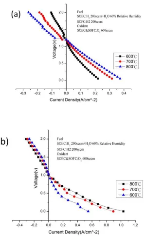
Figure 1. (a). Influences of temp on SOEC/SOFC polarization of OEIH with oxygen electrode: LSCF; (b). Influences of temp on SOEC/SOFC polarization of OEIH with oxygen electrode: LSM
[image:5.596.154.450.146.632.2]
flowrate of 250 sccm are directed to the surfaces of the oxygen electrode and the hydrogen electrode, respectively. For OEIH with oxygen electrodes – LSCF, the current densities (CDs) at a volt of 0.6 V are 84, 138, 176 mA/cm2 at temps of 600, 700, and 800 ℃, respectively. For OEIH with oxygen electrodes – LSM, the CDs at a volt of 0.6 V are 99, 218, 283 mA/cm2 at temps of 600, 700, and 800 ℃, respectively. In SOEC mode, H2 flowrate of 200 sccm with 60 vol. % humidity) is directed to the surface of the hydrogen electrode. For OEIH with oxygen electrodes – LSCF, the CDs at a volt of 1.3 V are -19, -45, -93 mA/cm2 at temps of 600, 700, and 800 ℃, respectively. For OEIH with oxygen electrodes–LSM, the CDs at a volt of 1.3 V were -39, -51, -82 mA/cm2 at temps of 600, 700, and 800 ℃, respectively. SOFC/SOEC performances improve with raising temps [11-14]. The factors dominate this result are: O2− penetrate the YSZ electrolyte, and electro-chemical reaction on the electrode are thermally-activated. In addition, OEIH with oxygen electrode – LSM performs better compared to that with oxygen electrode – LSCF in SOFC mode whereas OEIH with oxygen electrode – LSCF performs better in SOEC mode.
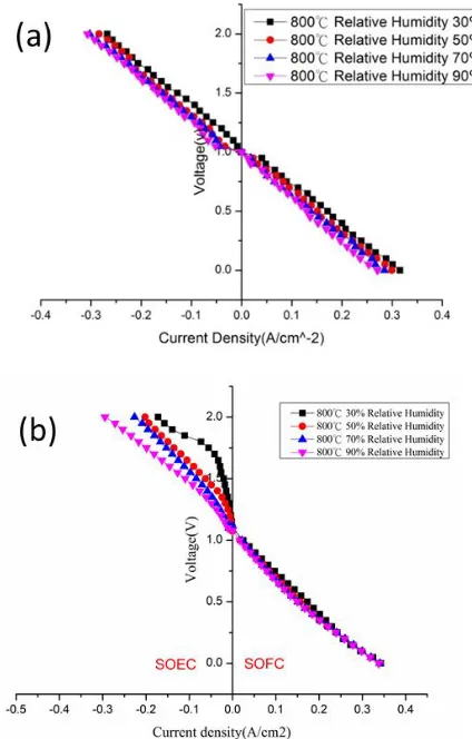
Besides the influence of temp, influence of humidity on SOFC/SOEC with oxygen electrode-LSM, LSCF are reported as illustrated in Fig. 2 (a) and 2(b), respectively. In SOFC mode and for OEIH with oxygen electrodes – LSCF, the CDs at temp of 800℃ were 141, 123, 111, 107 mA/cm2 with humidity of 30, 50, 70, and 90 % vol.% H2O, respectively.
[image:6.596.195.407.379.711.2]
In SOEC mode, and for OEIH with oxygen electrodes – LSM, the CDs at temp of 800℃ were 143, 127, 121, 119 mA/cm2 with humidity of 30, 50, 70, and 90 % vol.% H2O, respectively. For OEIH with oxygen electrodes – LSCF, the CDs at temp of 800℃ were -70, -94, -100, -113 mA/cm2 with humidity of 30, 50, 70, and 90 % vol% H2O, respectively. For OEIH with oxygen electrodes–LSM, the CDs at temp. of 800℃ were -8, -17, -37, -48 mA/cm2 with humidity of 30, 50, 70, and 90 % vol% H2O, respectively. The performance of SOEC improved with increasing humidity while performance of SOFC decreased with increasing humidity [10, 15, 16]. Although OEIH with oxygen electrode – LSM performs slightly better compared to that with oxygen electrode – LSCF in SOFC mode for all kinds of humidity, OEIH with oxygen electrode – LSM performs much worse compared to that with oxygen electrode – LSCF in SOEC mode. Results by Marina [17] also showed LSCF performs better compared to that with oxygen electrode – LSM in SOEC mode, although different composition of home-made (La0.6Sr0.4)0.98 Co0.2 Fe0.8 is utilized.
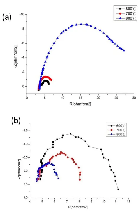
[image:7.596.164.409.327.697.2]3.2 Characterization by electrochemical impedance spectroscopy
To further investigate the influence of temp on the oxygen electrodes of the OEIH, an electrochemical impedance spectroscopy (EIS) is conducted, followed with SOFC experiment. The frequency range used is from 10 mHz to 10 kHz while the current is set at 0.5 A. As shown in Fig. 3(a), the cell ohmic resistances of OEIH with oxygen electrode - LSCF are 3.31 Ω‧ cm2, 3.34 Ω‧ cm2, and 3.52 Ω‧ cm2 at temps of 800, 700, 600 ℃ under high frequency operation ,respectively. The cell ohmic resistances increase with decreasing temp.. Cell ohmic resistances are simplified as the resistance of the electrolyte Hence, the electrolyte resistances increase with decreasing temp. meant that the oxygen ions penetrating through the electrolyte are thermally activated. Under low frequency operation, the intersects of a semi-circle with the x-axis of represents polarization resistances of the electrodes. As illustrated in Figure 3(a), the electrode resistances are 7.0 Ω‧ cm2, 8.3 Ω‧ cm2 and 27.2 Ω‧ cm2 at temperatures of 800, 700 and 600℃ respectively. Since polarization resistance of hydrogen electrodes is typically small for operating on hydrogen fuel, the polarization resistance can be attributed to oxygen electrode only. Thus r the oxygen electrode resistance also increased with decreasing temp. Thus, the oxygen reduction at the oxygen electrode are also thermally activated.
As shown in Figure 3(b), the cell ohmic resistances of OEIH with oxygen electrode – LSM are 4.56 Ω‧cm2, 4.61 Ω‧cm2, and 4.85 Ω‧cm2 at temperatures of 800, 700, 600 ℃, respectively, under high frequency operation. The cell ohmic resistances are higher compared to that OEIH with oxygen electrode-LSCF. Under low frequency operation, the electrode resistances are 6.5 Ω‧ cm2, 8.1 Ω‧ cm2 and 11.2 Ω‧ cm2 at temps of 800, 700 and 600℃, respectively. The polarization resistances of oxygen electrode are lower compared to that OEIH with oxygen electrode – LSCF. From the EIS study, it is concluded that the lower electrode resistance of OEIH with oxygen electrode – LSM contributed to higher SOFC performance compared to that of OEIH with oxygen electrode – LSCF as shown in Sec. 3.1. Thus, it is concluded that the oxygen electrode polarization is critically significant for SOFC.
3.3 Cyclic durability test of SOEC/SOFC
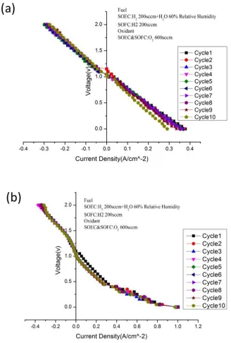
Figure 4. (a) Cyclic durability test of OEIH with oxygen electrode – LSCF; (b) Cyclic durability test of OEIH with oxygen electrode – LSM
[image:9.596.147.475.84.570.2]
Figure 5. (a). Effect of cycling on EIS spectra of OEIH with oxygen electrode: LSCF; (b). Effect of cycling on EIS spectra of OEIH with oxygen electrode: LSM
[image:10.596.115.453.96.602.2]
respectively. From the EIS study, it is found that there is no obvious cell resistance increase with cycling tests, however, the electrode resistance increases significantly with cycling tests. Asillustrated in figure 5(b), the cell ohmic resistances of OEIH with oxygen electrode – LSM are 4.7 Ω‧cm2, 4.8 Ω‧cm2, and 4.8 Ω‧ cm2 with cycling number 1, 5 and 10, respectively. The electrode resistances are 6.0 Ω‧ cm2, 6.3 Ω‧ cm2 and 6.7 Ω‧ cm2 with cycling number 1, 5 and 10, respectively. Apparently, both cell resistance and electrode resistance increase slightly with increasing cycling numbers. Although SOFC performance drop of nearly 20% for OEIH with oxygen electrodes – LSCF, and LSM, the EIS spectra is quite different during cycling tests. Therefore, microstructure characterization is particularly important to further investigate the microstructure of OEIH structure between post-sintering and after cycling test.
3.4 Microstructure characterization
[image:11.596.69.530.295.646.2]
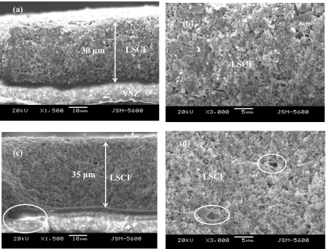
To investigate structure varitation during the SOEC/ SOFC cycling operations, analysis of the structure of OEIH are essential. The structure would be considerably varied after the OEIH co-sintering process, as well as during SOEC/SOFC operation. From side view of OEIH, the structure variation between sintering and after ten SOFC/SOEC cycling operations is examined. The side view of a post-sintering OEIH, illustrated in figure 6(a), indicates two layers of the electrolyte (YSZ), and the oxygen electrode (LSCF, La0.8Sr0.2Co0.2Fe0.8), respectively. Besides the thickness of oxygen electrode (= 30 μm), the SEM image indicates the smoothness of the oxygen electrode and its well connection with the electrolyte after the sintering process. As illustrated in figure 6(b), the SEM image indicates the structure of the oxygen electrode whereas LSCF indicates a less-porous structure after the sintering process.
Figure 7. (a) Side view of post-sintering OEIH with oxygen electrode - LSM (oxygen electrode/electrolyte, 1,700×); (b) Side view of post-sintering OEIH with oxygen electrode - LSM (oxygen electrode, 3,300×); (c) Side view of OEIH with oxygen electrode - LSM after ten SOEC/SOFC cycling operation (oxygen electrode/electrolyte/hydrogen electrode, 700×) ; (d) Side view of OEIH with oxygen electrode - LSM after ten SOFC/SOEC cycling operation (oxygen electrode/electrolyte, 1,700×)
[image:12.596.91.508.270.585.2]
explanation for the electrode resistance increase and significant performance decrease after ten SOEC/SOFC cycling operation discussed in section 3-4 .
As illustrated in figure 7(a) for OEIH with oxygen electrode-LSM, the SEM image of the structure of the oxygen electrode indicates a porous structure after the sintering process. Also, thickness increase (4μm = 32μm - 28μm) of oxygen electrode is also observed from figures 7 (b) and (d). In addition, there is obvious cavities (highlighted as ○), between oxygen electrode and electrolyte after ten SOEC/SOFC cycling test as shown in figure 7(d). This partly explained that ohmic resistance increased and thus performance decreased after SOFC/SOEC cycling test. Cavities with considerable sizes have also been observed by Li [19] in the interface between the oxygen electrode and electrolyte after SOEC operation, without apparent discrete
3.5 X- ray diffraction
[image:14.596.96.481.80.701.2]
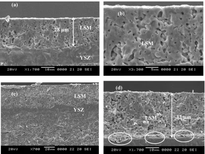
The XRD patterns of the hydrogen electrodes for both post-sintering and after SOEC/SOFC operation are slightly different. The generated peaks (solid arrow) and vanished peaks (dash arrow) in figure. 8(a) shows that nickel turn to nickel oxide during SOFC/SOEC cycling test. Eguchi [20] and Marina [17] indicated Ni/YSZ activity drop when operated at excessive humidity. They concluded that excessive humidity and low hydrogen percentage might results in the Nickel oxidation followed by an electrode activity loss. With regard to the XRD patterns of the oxygen electrode-LSCF illustrated in figure 8(b), the patterns for both post-sintering and after SOEC/SOFC cycling operation are equal. With regard to the XRD patterns of the oxygen electrode- LSM illustrated in figure 8(c), the peaks are somewhat different after SOEC/SOFC operation compared to those of post-sintering, new peaks of unknown constitutes are produced after SOEC/SOFC operation. The XRD patterns of the oxygen electrode- LSM after SOEC/SOFC cycling operation are composed of LSM and YSZ. The unknown peaks are resulted from the diffusion of YSZ electrolyte to oxygen electrode during SOEC/SOFC cycling operation. The composition change as well as weak connection of OEIH with oxygen electrode – LSM from electrolyte after ten SOFC/ SOEC cycling test are the main reasons lead to obvious performance drop.
4. CONCLUSIONS
In this study, the co-sintered OEIH with oxygen electrodes – LSCF and LSM, have been operated in both SOFC and SOEC modes for energy storage and generation purposes, respectively. The performances of the SOFC/SOEC are both thermally-activated, increasing with operating temp. Performances of OEIH with oxygen electrode- LSM and LSCF increase with humidity in SOEC mode and decrease with SOFC mode. OEIH with oxygen electrode – LSM performs better compared to that with oxygen electrode – LSCF in SOFC mode whereas OEIH with oxygen electrode – LSCF performs better in SOEC mode. Although SOFC performance drop of nearly 20% for OEIH with oxygen electrodes – LSCF and LSM after ten SOFC/SOEC cycling test, the reasons for each case is quite different. Structure change within the oxygen electrode-LSCF after the ten SOEC/SOFC operation would be an interpretation for obvious performance decrease after ten SOFC/SOEC cycling operation. And, the composition change as well as weak connection (cavities generation) of OEIH with oxygen electrode – LSM from electrolyte after ten SOFC/ SOEC cycling test are responsible for the main reasons leading to performance drop.
ACKNOWLEDGEMENTS
The authors appreciatively express thanks to the Ministry of Science and Technology, R.O.C. under contracts 104-2221-E-155-040 and 101-3113-E-155-001 and the Taiwan Power Company for the financial sponsor.
References
2. A. Shirazi, M. Aminyavari, B. Najafi, F. Rinaldi and M. Razaghi, International Journal of Hydrogen Energy, 37 (2012) 19111
3. V. Saribog and F. Öksüzömer, Applied Energy, 93 (2012) 707
4. Y. H. Zhang, J. Liu, X. Q. Huang, Z. Lu and W. H. Su, International Journal of Hydrogen Energy, 33 (2008) 775
5. P. Batfalsky, V. A. C. Haanappel, J. Malzbender, N. H. V. Shemet, I. C. Vinke and R. W. Steinbrech, Journal of Power Sources, 155 (2006) 128
6. S. A. Grigoriev, P. Millet, S. A. Volobuev and V. N. Fateev, International Journal of Hydrogen Energy, 34 (2009) 4968
7. P. Medina and M. Santarelli, International Journal of Hydrogen Energy 35 (2010) 5173 8. J. M. Gras and P. Spiteri, International Journal of Hydrogen Energy 18 (1993) 561 9. M. A. Laguna-Bercero, J. A. Kilner and S. J. Skinner, Solid State Ionics, 192 (2011) 501
10.A. Brisse, J. Schefold and M. Zahid, International Journal of Hydrogen Energy 33 (2008) 5375 11.G. B. Jung, J. Y. Chen, C. Y. Lin, S. Y. Sun, International Journal of Hydrogen Energy, 37 (2012)
15801
12. P. Leone, M. Santarelli, P. Asinari, M. Calì, R. Borchiellini, Journal of Power Sources, 177(2008) 111
13. D. Rembelski, J.P. Viricelle, L. Combemale, M. Rieu, Fuel Cells, 12 (2012) 256 14. H Fan, M Keane, P. Singh, M Han, Journal of Power Sources, 268 (2014) 234
15.X Zhang, J. E. O’Brien, R. C. O’Brien, G. K. Housley, Journal of Power Sources, 242 (2013) 566 16.F He, D Song, R Peng, G Meng, S Yang, Journal of Power Sources, 195 (2010) 3359
17.O. A. Marina, L. R. Pederson, M. C. Williams, G. W. Coffey, K. D. Meinhardt, C. D. Nguyen, E. C. Thomsena, Journal of The Electrochemical Society, 154 (5) (2007) B452
18.H. Fan, M. Keane, N. Li, D. Tang, P. Singh, M. Han, International Journal of Hydrogen Energy 39 (2014) 14071
19.G. Q. Li, Y. Zheng, W. Guan, L. Jin, C. Xu, W. G. Wang, International Journal of Hydrogen Energy, 39 (2014) 108033
20.K. Eguchi, T. Hatagishi, and H. Arai, Solid State Ionics, 86 (1996) 1245.

![Synthesis and Luminescence behavior of SrS:EuCeX[X=La,Tb,Dy]Nano sized phosphor fabricated through modified solid state reaction processes for white LED](data:image/gif;base64,R0lGODlhAQABAIAAAP///wAAACH5BAEAAAAALAAAAAABAAEAAAICRAEAOw==)