City, University of London Institutional Repository
Citation
:
Koller, Anton W. (2014). The friction coefficient of soft contact lens surfaces in relation to comfort and performance. (Unpublished Doctoral thesis, City University London)This is the accepted version of the paper.
This version of the publication may differ from the final published
version.
Permanent repository link:
http://openaccess.city.ac.uk/13791/Link to published version
:
Copyright and reuse:
City Research Online aims to make research
outputs of City, University of London available to a wider audience.
Copyright and Moral Rights remain with the author(s) and/or copyright
holders. URLs from City Research Online may be freely distributed and
linked to.
City Research Online: http://openaccess.city.ac.uk/ [email protected]
The friction coefficient of soft contact
lens surfaces in relation to comfort and
performance.
A thesis submitted for the degree of Doctor of Philosophy
to City University London
Division of Optometry and Visual Sciences
by
Anton W. Koller
1
Index
List of Tables 6
List of Figures 11
ACKNOWLEDGEMENTS 14
Declaration: 14
Abstract 15
Chapter 1 - Introduction 16
1.1 Aims of this research 18
Chapter 2 - Anatomy and physiology of the eye 19
2.1 The Visual Organ: 19
Cornea and Sclera 20
Crystalline Lens 22
The Retina 23
The Uveal Tract 23
2.1 The eyelids 24
2.2 Tears 25
2.3 Structure of the tear film 25
2.4 Properties of the tear film 26
Chapter 3 - Contact lenses 27
3.1 Historical development 27
3.2 Hydrophilic Contact Lens Materials 29
3.3 Silicone Contact Lenses 32
3.4 Silicone Hydrogel Contact Lenses 32
3.5 Contact lens manufacturing techniques 33
3.6 Soft contact lens fitting 34
2
What keeps the lens in position on the eye? 37
3.8 Contact lens comfort 38
Chapter 4 - Friction 40
4.1 Introduction 40
4.2 Friction and Contact Lenses 41
4.3 Fluid friction between solids 42
4.4 Polymer friction 43
4.5 Viscosity 44
4.6 Rheology 44
Plastic fluids (Bingham- substances) 45
Dilatant fluids 45
Thixotropic fluids 45
4.7 Tribology 45
Stick-slip phenomenon 46
Surface quality 47
4.8 Contact lens friction and lubricity 47
4.9 Review of soft contact lens tribometry 56
Chapter 5 - Rationale for in vitro experiments 61
5.1 Introduction 61
5.2 Experiment 1 - The construction and testing of a Contact Lens Tribometer 64
5.3 Physical principles 65
5.4 The force to be applied to the substrate 66
5.5 Apparatus 66
Tribometer Schema 66
Mechanical Scale 68
High resolution stepper motor 69
3
NC-Pilot stepper motor controller 71
Kistler high resolution force sensor 9215-1 72
Charge Amplifier Kistler ICAM 5073 73
Kistler Manuware Software 73
Substrate used for testing 74
Hydrogel samples 75
5.6 Experiment 1A - Verification of linear and radial swell rates 76
5.7 Experiment 1B – Calibration of the sensor 78
5.8 Experiment 2 –Friction coefficients of the reference materials 79
5.9 Experiment 3 – Evaluation of soft lens materials 87
Chapter 6 - Rationale for the in vivo experiments 97
6.1 Introduction 97
6.2 Corneal shape, bulbar shape and contact lens design 98
6.3 Predicting contact lens geometry by a mathematical approach 100
6.4 Design of the experimental soft lenses 108
6.5 Experiment 4 – Use of a Scheimpflug image 110
Discussion 111
6.6 Experiment 5 - Evaluation of the PMMA semi-scleral lenses on one eye. 112
Introduction 112
Materials 112
Method 113
Discussion 116
6.7 Experiment 6 - Measurement of soft lens parameters at elevated temperature 118
Introduction 118
Aim: 120
Materials 120
4
Results 121
Discussion 121
Chapter 7 - In vivo experiments 123
7.1 Ethical approval, inclusion and exclusion criteria 123
Ethical approval 123
Inclusion criteria 123
Exclusion criteria 123
Subjects 124
7.2 Equipment and materials 125
7.3 The clinical record forms. 128
Clinical Record Form 1 (CRF1) 128
Clinical Record Form 2 (CRF2) 129
Clinical Record Form 3 (CRF 3) 129
7.4 Experiment 7 – In vivo experiments 130
Introduction 130
Materials 130
Methods 131
Results 139
7.5 Discussion of the in-vivo results 161
Chapter 8 - General discussion and conclusions 170
Chapter 9 - CONCLUSIONS 184
Chapter 10 - Appendices 186
10.1 Results of CRF 1 tests 186
10.2 Results of CRF 2 tests 189
Performance 189
5
11.1 Annex A- The influence of scleral shape in relation to the Back Optic Zone
Radius of a monocurve contact lens 202
11.2 Annex B- Patient information and consent form 204
11.3 Annex C- Clinical record forms 1-3 207
Chapter 12 - References 211
6
List of Tables
Table 2.1 Surface parameters of Liu’s eye model ... 20
Table 2.2 Refractive indices of Liu’s eye model ... 20
Table 3.1 ISO 18369-1 Classification of soft contact lens materials. ... 30
Table 3.2 ISO 18369-1 Classification of soft contact lens materials ... 31
Table 3.3 An example of how the ISO nomenclature is used ... 31
Table 4.1 Average circumference of sphere segments. ... 54
Table 4.2 Sample calculations related to mass causing force ... 55
Table 4.3 Reported friction coefficients ... 60
Table 5.1 Stepper motor settings for a 24mm diameter disc. ... 72
Table 5.2 Specification of tested materials... 75
Table 5.3 Linear swell rates of the five chosen materials. ... 77
Table 5.4 Radial swell rates of the five chosen materials ... 78
Table 5.5 Friction coefficients of rigid materials tested against each other. ... 83
Table 5.6 Coefficient of friction. ... 85
Table 5.7 Resulting (frictional) force for all tests normalised to a 10 g load. ... 86
Table 5.8 Coefficient of friction for materials... 86
Table 5.9 Dry friction mesurements of 5 simulated blinks, ... 92
Table 5.10 Borderline friction measurement of 5 simulated blinks, ... 92
Table 5.11 Mixed friction measurement of 5 simulated blinks, ... 93
Table 5.12 Friction measurement of 5 simulated blinks, using the lubricating agent Celluvisc. ... 93
Table 6.1 Calculation of the scleral diameter and radius ... 103
Table 6.2 Calculated monocurve BOZRs for a 14.0mm diameter TD lens. ... 105
Table 6.3 Calculated monocurve lens ... 105
7
Table 6.5 The production data and the measured values for the set of semi scleral
PMMA lenses. ... 117
Table 6.6 Comparison of radii, diameters and sags between ambient room temperature and 34°C for the five different soft lens materials. ... 121
Table 7.1 Sequence of lenses tested in subjects eyes ... 132
Table 7.2 Contrast sensitivity values. Rows 1-8 define contrast, ... 135
Table 7.3 Contrast sensitivity for participating subjects with spectacle prescription. ... 139
Table 7.4 CRF1 results: Ocular tissue grades and corneal diameters for all 16 subjects. ... 140
Table 7.5 CRF1 results: Tear meniscus height at lower lid and keratometer readings. ... 141
Table 7.6 Best spectacle correction. ... 142
Table 7.7 Excluded subjects and reason for exclusion. ... 143
Table 7.8 The retinoscopy spot findings and tear break-up times. ... 144
Table 7.9 Best aligned PMMA trial lenses as described in 6.6 ... 145
Table 7.10 Comfort values as recorded using the VAS. ... 146
Table 7.11 VAS results in Table 7.9 minus the VAS results using PMMA trial lenses ... 147
Table 7.12 Average VAS results in cm for each material and each subject. ... 148
Table 7.13 Comfort difference in VAS between PMMA semi scleral test lenses and the tested materials for the five subjects... 149
Table 7.14 Results of a two way analysis of variance in comfort between materials and subjects tested. ... 150
Table 7.15 Average, SD, median and absolute median (MAD) of lens movement for VSO 38, LM55 and GM3 materials. ... 151
8
Table 7.17 Average and standard deviation of vertical lens movement... 153
Table 7.18 Mean and average lens movements after a blink. ... 153
Table 7.19 Results of PUT test ... 156
Table 7.20 Frequency of lens movements for lenses judged as normal using the PUT ... 156
Table 7.21 The number of lenses judged as loose using the PUT. ... 157
Table 7.22 Visual acuitiy with soft lenses and best overcorrection ... 158
Table 7.23 Difference in VA between spectacle correction and VA obtained with contact lens plus over-correction ... 158
Table 7.24 Summarised difference between contrast sensitivity with spectacle correction and CS with contact lenses and overcorrection. ... 159
Table 7.25 Average contrast sensitivity results for all subjects using best correction ... 159
Table 7.26 Average difference between CS results with contact lenses using best overcorrection and best spectacle correction ... 159
Table 7.27 Summarised retinoscopic spot occurrences for all five materials. ... 160
Table 7.28 CRF 3 results ... 161
Table 7.29 Comfort results from research literature. pm = afternoon ... 162
Table 7.30 Comfort difference on the VAS between PMMA semi scleral trial lenses and the 5 soft lens materials. ... 163
Table 8.1 Published coefficients of friction for a range of contact lenses. ... 175
Table 8.2 Coefficients of friction measured under unlubricated conditions and different lubricated states with the experimental contact lens tribometer. ... 176
Table 8.3 Average VAS differences in comfort between the tested material and PMMA test lens. Positive values indicate better comfort. ... 179
Table 8.4 Average visual acuity with best spectacle correction and with contact lenses ... 180
9
Table 8.6 Overall retinoscopic spot appearances with the best overcorrection. ... 181
Table 8.7 Average lens movement with video analysis compared with CoF at borderline and mixed lubrication with saline and mixed lubrication with a lubricating agent. ... 182
Table 8.8 Spearmans rho rank correlation for CL movement after a blink and CoF ... 182
Table 8.9 Push-up test results compared with borderline and mixed friction CoF’s ... 183
Table 10.1 Contrast sensitivity with best correction CRF 1 for selected individuals ... 186
Table 10.2 Results of CRF 1: Fundamental data, K-readings, spectacle correction and if CL wearer. ... 187
Table 10.3 Results of CRF1: Exterior part of the eye, Tear meniscus Retinoscopic spot, NIBUT, lid tension, exclusion reasons ... 188
Table 10.4 Visual acuity with soft CL and best overcorrection ... 189
Table 10.5 Visual acuity with soft CL and best overcorrection minus best visual acuity with spectacle correction. ... 190
Table 10.6 Retinoscopic spot occurrences VSO 38 material ... 191
Table 10.7 Retinoscopic spot occurrences LM 55 material ... 192
Table 10.8 Retinoscopic spot occurrences GM3 material ... 193
Table 10.9 Retinoscopic spot occurrences VSO 75 material ... 194
Table 10.10 Retinoscopic spot occurrences Definitive material ... 195
Table 10.11 Contrast sensitivity 30 min. after lens insertion ... 196
Table 10.12 Comparison of contrast sensitivity with CL + overcorrection and spectacle contrast sensitivity ... 197
Table 10.13 Soft lens friction by measuring lens movement between blinks ... 198
10
Table 10.15 Average, SD, median and median absolute deviation for VSO75 and
Definitive materials. ... 199
Table 10.16 Ratio between lid force and lens movement after blink ... 199
Table 10.17 Prevalence of vertical travel in 0.1mm increments after blink... 200
Table 10.18 Results of push up tests where n = normal and l = loose. ... 201
Table 11.1Clinical Record Form 1 (CRF 1) ... 207
Table 11.2 Clinical record Form 2 page 1 (CRF2) ... 208
Table 11.3Clinical record form Page 2 ... 209
11
List of Figures
Figure 2.1 A cross-section of the human eye ... 19
Figure 2.2 A cross section of the human cornea ... 21
Figure 2.3 A longitudinal section of the anterior part of the eye ... 23
Figure 2.4 The lacrimal apparatus right side ... 24
Figure 4.1 Dynamic friction of Polytetrafluoroethylene (PTFE) ... 44
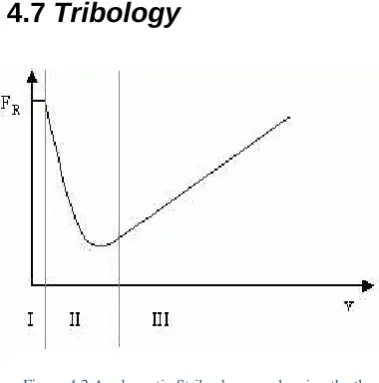
Figure 4.2 A schematic Stribeck curve showing the three different friction phases. 45 Figure 4.3 Stick-slip phenomenon seen while adding force five times for 3 seconds ... 47
Figure 4.4 Contact lens rotation in situ. Due to the structure and movement of the lid, the lens of the right eye rotates in the opposite direction to that of the left eye. 48 Figure 4.5 Explanation of flat, parallel (aligned) and steep contact lens fit. ... 48
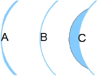
Figure 4.6 (A) minus lens with peripheral shoulder, (B) back surface parallel to front surface (C) positive lens with anterior second curve... 48
Figure 4.7 The relationship between force, mass and gravity. ... 50
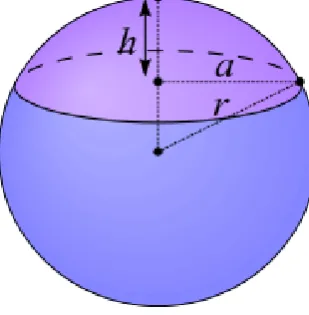
Figure 4.8 Spherical cap (Wikipedia 2015) ... 50
Figure 4.9 Force upon a projected area ... 51
Figure 4.10 a projected area. ... 51
Figure 4.11 Explanation of average circumference of a sphere or sphere segment .. 52
Figure 4.12 Explanation for the calculation of the slice diameter of a sphere ... 53
Figure 5.1 Tribometer Schema ... 66
Figure 5.2 Tribometer set up. ... 67
Figure 5.3 Tribometer base showing the substrate attached to the stepper motor and the disc holder ... 68
Figure 5.4 Tribometer balance attached to base. ... 68
Figure 5.5 Torque graphs for stepper motor ... 70
12
Figure 5.7 Kistler low force sensor 9215-1 ... 72
Figure 5.8 Kistler Charge Amplifier ... 73
Figure 5.9 Sensor readings as shown on the computer screen. ... 74
Figure 5.10 Calibration of the low force sensor. ... 78
Figure 5.11 Oscilloscope display during sensor calibration ... 79
Figure 5.12 10g total force on top of the substrate ... 81
Figure 5.13 Example reading of static friction. ... 82
Figure 5.14 Oscilloscope reading for HEMA ... 90
Figure 5.15 Oscilloscope reading for the LM material ... 90
Figure 5.16 Oscilloscope reading for GM material ... 91
Figure 5.17 Oscilloscope reading of Definitive material at mixed friction. ... 91
Figure 6.1 Explanation of the scleral model ... 101
Figure 6.2 Separation of corneal and scleral sagittal heights ... 102
Figure 6.3 Composition of sagittal heights ... 104
Figure 6.4 Section of a monocurve contact lens with effective inner lens diameter ... 106
Figure 6.5 “Aligned” fit of a soft contact lens ... 106
Figure 6.6 Approximation of contact area (not to scale). Central angle α defined . 107 Figure 6.7 Scheimpflug image of the author’s left eye. ... 110
Figure 6.8 Explanatory drawing showing the resulting radius ... 110
Figure 6.9 Semi-scleral PMMA lens 8.6/14.5mm. ... 114
Figure 6.10 Semi-scleral PMMA lens 8.7/14.5mm. ... 114
Figure 6.11 Semi-scleral PMMA Lens 8.80/14.5mm. ... 114
Figure 6.12 Semi-scleral PMMA lens 8.9/14.5mm ... 115
Figure 6.13 Semi-scleral PMMA lens 9.0/14.5mm ... 115
13
Figure 6.15 Semi-scleral PMMA lens 9.2/14.5mm. ... 116
Figure 7.1 Reticule photograph for calibration ... 137
Figure 7.2 Overlay demonstration with 3 visible out of 4 overlaid frames. ... 138
Figure 7.3 Comfort separated by material types in ascending order. ... 148
Figure 7.4 Comfort difference between the PMMA semi scleral lenses and the tested soft lenses. ... 149
Figure 7.5 Median lens movement in mm. ... 152
Figure 7.6 The association between lens movement and friction coefficient. ... 154
Figure 7.7 Contact lens movement versus lid force for the five subjects... 155
Figure 7.8 Scattergram of lens movement, measured in 0.1mmsteps, after a blink 155 Figure 7.9 Lens movement for lenses judged as normal using the PUT ... 156
Figure 7.10 Lens movement for the lenses judged as loose (using the PUT) ... 157
Figure 7.11 Ultrahigh resolution OCT of the limbal area of an eye and a conjunctival impression caused by a soft lens ... 167
Figure 8.1 Average coefficients of friction in ascending order ... 177
14
ACKNOWLEDGEMENTS
First of all I thank my supervisor Dr. Mike Port for suggesting the idea for this thesis, for his patience, for his support, the elegant way of keeping me on track and leading me, the non-native English speaking student, over possible obstacles.
Further I thank my second supervisor Prof. David Edgar for his support in preparing my thesis resolving formal tasks. As a foreign student I am further grateful for the support from City University which was excellent. I also thank my dear friend Univ. Prof. Dr. Steinkogler for his help to resolve legal requirements with the Vienna Ethics committee. I am also grateful to my daughter Victoria who managed to recruit my subjects for the in vivo tests and helped me to manufacture the huge number of test lenses. She was an excellent assistant who was cheerful, helpful and supportive. I am also grateful to the Vienna “Akademie für Augenoptik, Optometrie und Hörakustik” for using their equipment which was not available in my own premises. Last but not least I am grateful to my wife Eva, who encouraged me to stay seated in front of my personal computer to write this thesis and being so very patient for this last nearly two years as well as keeping me out of other enterprises which might have been time-consuming.
Finally I thank Contamac Ltd. and Vista Optics Ltd. for providing contact lens blanks for the tests.
Declaration:
15
Abstract
The soft contact lenses of today are made from a variety of hydrogel materials. These materials have different properties in terms of water content, monomers, hardness and other tensile characteristics. It is likely that the frictional properties also vary between materials. It is known that constituents of the tear film interact with contact lens materials to form a biofilm on the lens surface. The hypothesis of this research is that although the frictional properties of lens materials may vary these properties do not affect the comfort and performance of the lenses in vivo. A tribometer is a device to measure the coefficient of friction of materials. There was no commercially available tribometer designed specifically for use with contact lens materials, so one was constructed and validated against standard solid materials. The same equipment was used to determine the friction coefficients of five
contemporary soft lens materials under different conditions of lubrication but, unlike other tribometers, this unique design simulated human blinking as far as possible. The experimental friction coefficients varied widely from 0.27 to 5.89 under
different conditions of lubrication. The largest variation between materials was seen using the most viscous lubricant.
For the in vivo studies the author coordinated the manufacture of 250 contact lenses, which were lathe cut and polished to a standard design, achieving exceptionally tight tolerances, using the same five materials. This rigourous process was carried out to minimise variations in the geometry of each contact lens. Subjects were screened to minimise ocular heterogeneities between subjects. Clinical performance of each lens was assessed using comfort, contrast sensitivity, visual acuity, entoptic phenomena, non-invasive tear break-up time and lens movement on the eye. In a clinical
16
Chapter 1 - Introduction
Since the first hydrophilic contact lenses manufactured by Wichterle, movement of soft contact lenses, in situ, has been judged as an indicator for comfort and
physiological tolerance. Because of the soft structure of the material, it was believed that fitting techniques similar to those used for hard contact lenses were not
required. Wichterle mentioned (Gasson, 2008)in a letter that contained basic instruction for a practitioner, that “if the patient has observed the formation of
Sattler’s veil during wear, the lens should be decentred for a certain period to
re-establish physiological conditions”. Research and experience in the following decades confirmed that movement of soft lenses on the eye is of high importance in order to maintain physiological and morphological conditions while a soft contact lens is worn (Gasson and Morris, 1992, Bürki, 1991, Hom and Bruce, 2006). Contact lens fitters have to consider contact lens geometry in relation to the ocular topography while, at the same time, attending to the physiological requirements of the eye. Despite the fitters efforts to ensure the best fitting lens, complications frequently occur following lens wear. An internet search produced more than two million hits regarding complications of contact lenses wear, while a search in PubMed found more than 2500 citations relating to this topic. Most of the
educational literature mentions complications in soft contact lens wear. For example, the “Manual of Contact Lens Prescribing” (Hom and Bruce, 2006) cites 200
publications on soft lens wear complications. With the use of “disposable” and planned replacement contact lenses, these problems have been partially solved. An example is the problem of non-soluble deposits on the anterior surface of
17
exchange with blinking, and friction is an important determinant of lens movement. Although the topic of friction in contact lens wear has been investigated using different lubricants and/or tear substitutes, these investigations have been carried out in an undifferentiated manner (Yao et al., 2008, Sivamani et al., 2003, Rennie et al., 2005, Kim, 2001, Niarn and Jiang, 1995) i.e. these investigations have only
considered specific conditions with specifically chosen materials and methods. To understand and appreciate the requirements for the surface structure of a contact lens and the resultant lens movement on the eye, the dynamics of contact lenses on the eye, lid dynamics and the surface characteristics of lenses and tissues all have to be evaluated.
The general anatomy and physiology of the eye is discussed in Chapter 2 of this thesis, with emphasis on the cornea, tears, tear film, and eyelids, all of which have particular relevance to the contact lens research which follows. Chapter 3 focuses on developments in contact lens materials, including PMMA, hydrophilic materials, silicone elastomers, silicone hydrogels, together with their different manufacturing processes, and soft contact lens fitting technique. This chapter concludes with consideration of contact lens movement on the eye and comfort when wearing contact lenses. In Chapter 4, the physics of friction is discussed, with particular emphasis on friction as it affects contact lens materials and contact lens wear. The topic of tribology, the investigation of friction, is introduced, and tribometry, the measurement of friction, is discussed in relation to contact lenses. Chapter 5
introduces and describes the in vitro experiments which were the precursor to the in vivo experiments which follow later in the thesis. A major element of Chapter 5 is the construction and testing of the author’s own design of tribometer, specifically constructed for use with contact lens materials and contact lenses themselves. This leads on to the preparation of lenses for the in vivo experiments described in Chapter 6. This required the design and construction to exceptionally rigourous tolerances of 250 soft contact lenses under the author’s supervision. These lenses were
18
subjects. The final chapter (Chapter 8) contains a general discussion and conclusions of this research.
1.1
Aims of this research
Our knowledge of the frictional behaviour of contact lens materials themselves requires expansion to increase our understanding of whether differences between materials might influence the success of contact lens wear and, if so, why some materials may perform better than others. The work presented in this thesis
19
(Reproduced with permission of Brent Cornell)
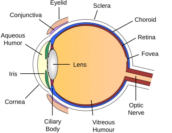
Chapter 2 - Anatomy and physiology of the eye
Optic Nerve
Fovea Retina Choroid Sclera
Cornea Iris
Lens Aqueous
Humor
Vitreous Humour Eyelid
Conjunctiva
[image:22.595.202.480.109.323.2]Ciliary Body
Figure 2.1 A cross-section of the human eye
2.1
The Visual Organ:
The visual organ consists of the two eyes, their protecting and supporting organs, the visual pathway and the visual cortex (Grehn, 2012). The light sensitive retina
represents the most important part of the eye. The retina is judged as an advanced extension of the brain consisting of several sequential switched neurons.
Electromagnetic wavelengths between 380 and 760 nanometres are able to stimulate the photo-receptors. Each location of the visible space corresponds to a related retinal area. The differentiation of the stimulating light sensations to the retina is called visual perception.
20
orbital cavity. The orbit contains multiple ocular muscles which control eye movement and various connective tissues.
Gullstrand (Helmholtz, 1909) “developed the most authorative model of the eye”. While this model and others, such as Emsley’s reduced eye, Listing’s reduced eye, or Schwiegerling’s eye are good for paraxial domains, modern models relate to the modulation transfer function (Sturzu and Luca-Motoc, 2011). The Arizona eye model (Greivenkamp et al., 1995) developed a method to calculate the changes of the optical properties of an eye and the resulting visual performance. Liu et al. (2005) proposed an eye model, containing a shell-structured lens. The parameters are given in Table 2.1 and Table 2.2.
Surface
Radius (mm)
Conic constant
Thickness (mm) Anterior surface of cornea 7.77 0.18 0.50 Posterior surface of cornea 6.4 -0.60 3.16 Anterior surface of lens 12.4 -0.94 4.02 Posterior surface of lens −8.10 0.96
Table 2.1 Surface parameters of Liu’s eye model
Surface Media
Index (543 nm) Anterior surface of cornea Cornea 1.3777 Posterior surface of cornea Aqueous 1.3371 Anterior surface of lens Lens Shell Posterior surface of lens Vitreous 1.3377
Table 2.2 Refractive indices of Liu’s eye model
Cornea and Sclera
The outermost layer of the eye is a connective tissue, which consists of the
transparent cornea and the white sclera. The junction between cornea and sclera is termed the limbus. The radius of the transparent cornea is 7.2 – 8.5 mm. It has a diameter of 10 – 13mm. The length of the eye is approximately 24mm.
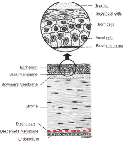
21
The anatomy of the cornea is as follows (Figure 2.2). The three layered epithelium consists, from outside to inside, of flat and cubic cells, two to three rows of thorn cells and cylindrical epithelial cells adhered to the basal membrane which resides on the transparent, glassy Bowman’s membrane, also named anterior elastic lamina, followed by the main structure, the substantia propria or stroma. Dua et al. (2013) described a 15µm thick layer between corneal stroma and endothelium withstanding up to 2 bars of pressure. The understanding and the function of this layer might influence the understanding of corneal diseases such as hydrops and pre- Descemet
dystrophies (Kanski and Bowling, 2012).
Descemet’s membrane covers the stroma at the posterior side of the cornea. The non- regenerating one layered corneal endothelium represents the inner corneal limit towards the anterior chamber of the eye.
The margins of the anterior chamber are the surface of the cornea, the chamber angle, the front surface of the iris and within the area of the pupil, the front surface of the crystalline lens. The junction between cornea and iris is called the chamber angle. Its adjacent structures are the trabecular meshwork and the canal of Schlemm. These structures are responsible for the drainage of the intraocular fluid (aqueous humour) produced by the ciliary body which is located in the posterior chamber. The 20-30 drainage channels connected to Schlemm’s canal end within the deep venous patch and partially in the conjunctival surface veins.
[image:24.595.134.346.56.305.2]Comfort and success of contact lens wear depends on the sensory responses of the cornea and conjunctiva. About seventy non myelinated nerve fibres, coming from the sensory nerve branches of the ophthalmic nerve, enter the cornea radially developing a dense structure by binary branching. Most of these ciliary nerves are
Figure 2.2 A cross section of the human cornea (reproduced with the permission of Elsevier, Dua’s layer
22
located beneath the basal membrane while some nerves reach the epithelium and end near the epithelial surface (Augustin, 2007). Sensory events on the corneal surface trigger the blink reflex, a protective mechanism of the eye. Temperature drop because of tear evaporation is one of the reasons to blink in order to keep the eye wet and lubricated. For this reason, contact lens wearers mostly blink habitually as their blink reflex is not directly triggered because the tears between the contact lens and the eye do not evaporate and, therefore, corneal temperature does not drop (Wolkoff et al., 2005). Honegger et al. (1980) compared the duration of stay of ophthalmic preparations in the conjunctival sac. Watery and a viscous formulations were compared. While 17.5% ± 6.3% of the watery preparation remained in the conjunctival sac, 69.5% ± 17.4% of the viscous formulation containing 2% methylcellulose remained after one minute of installation. Forty minutes after instillation approximately 10% of the watery drops remained in the eye compared with approximately 20% of the drops containing methylcellulose. An initial tear turnover of 52%/minute was reported by Nelson (1995) from adults between 20 and 45 years of age and of 38%/minute from persons between 50 and 89 years of age. The physiological tear turnover rate of the younger group was reported to be 16%/minute compared with 18%/minute for the older group using a
fluorophotometric method. Another study (Tomlinson and Khanal, 2005) reported tear turnover rates between 7%/minute and 22.2 %/minute in normal subjects measured by different authors. They observed a significant decrease of fluorescein concentration within the first five minutes after instillation and suggested that this was caused by reflex tearing. As mentioned, tear exchange not only plays an important role in keeping the cornea transparent and to assure metabolic exchange but also requires attention in conjunction with the efficacy, the use and the dilution of tear substitutes and lubricants in vivo.
Crystalline Lens
23
of the circular ciliary muscle alter the curvature of the lens and enable the eye to have proper focus at distance and near. This phenomenon is called accommodation. The space behind the crystalline lens is filled with the vitreous body and consists of a gel embedded in a fine structural substance. The refractive indices of the refractive portions of the eye are as follows:
Cornea: 1.376
Aqueous humour: 1.336 Vitreous body: 1.336
The Retina
The retina or neural tunic of the eye should be considered as a brain extension responsible for perception of visual events and translating them to nervous signals. Light entering the eye and absorbed by the photoreceptors, the rods and cones, is transposed to electric signals via a chemical reaction using rhodopsin. These signals reach the visual cortex via the retinal ganglia and the optic nerve. They are separated at the optic chiasma as left and right hemisphere signals passing through the optic tract, the lateral geniculate body and the optic radiation of each side (Damms and Guzek, 2014).
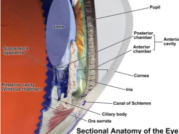
The Uveal Tract
The iris, the ciliary body and the choroid form the uvea. The iris separates the anterior chamber from the posterior chamber and has the pupil in its centre. It slides on the front surface of the
[image:26.595.139.320.541.676.2]crystalline lens and is the variable diaphragm (aperture) of the eye. The iris root joins the ciliary body which controls accommodation. The ciliary body also produces the aqueous humour which flows from the posterior chamber to the anterior chamber and leaves the
Figure 2.3 A longitudinal section of the anterior part of the eye
24
intraocular structure through the canal of Schlemm and the trabecular meshwork. The choroid is separated from the retina by the lamina vitrea which sits on the retinal pigment epithelium of the retina. The next layer is the chorio-capillaris which
provides nutrition to the outer layers of the retina.
2.1
The eyelids
The eyelids consist of outer skin, and contain the circular orbicularis muscle innervated by the nervus facialis, which closes the upper lid and the tarsal plate containing the Meibomian glands. The inner layer of the eyelid is the tarsal conjunctiva which everts at the fornix and connects to the eye at the limbus. It contains mucin producing goblet cells, Krause’s and Wolfrings glands which are accessory tear glands. The eyelashes are located at the outer edge of the lids. The glands of Zeiss and Moll are located in the neighbourhood of the lashes. The upper lid is opened by the levator palpebrae, innervated by the nervus oculomotorius and the smooth Muller’s muscle innervated by the sympathetic nerve. The tension of the upper eyelid plays an important role in contact lens movement. It is well known (Ehrmann et al., 2001) that lid tension is different from one person to another and it is reported that 10.7 mN/mm to 35.5mN/mm is the range of pulling motion. A figure of 10.3mm Hg which equals 1.4mN/mm2 has been reported in previous literature (Miller, 1967). More recent literature (Shaw et al., 2009) described new
piezoelectric techniques for assessment but only provided raw data. The eyelids have a protective task and help to keep the eye wet by blinking. The sensory
innervation of the upper eyelid arises from the infratrochlear the supratrochlear, the supraorbital and the lacrimal nerves of the ophthalmic branch of the trigeminal nerve. The infratrochlear nerve also supplies the skin of the lower lid. Stapleton et al. (2013) write that the eyelid margins are supplied by branches of the
a. tear gland / lacrimal gland, b. superior lacrimal punctum, c. superior lacrimal canal, d. tear sac / lacrimal sac, e. inferior acrimal punctum, f. inferior
[image:27.595.129.315.184.377.2]lacrimal canal, g. nasolacrimal canal (Wikimedia commons 2014)
25
supratrochleal, supraorbital, infratrochlear and lacrimal nerves and mention the importance of the eyelid and the cornea as a “key contact zone between the contact
lens and the ocular surface” and mention that the relationship between contact lens wearing and ocular comfort has been known for many years. The eyelids provide protection for the eye, and distribute the tears over the eye, keeping it wet, clear and clean (Kaufmann and de Decker, 2003). The ‘lid wiper’ is the 0.4 to 0.6mm wide inner conjunctiva of the upper lid near the canthus that wipes the ocular surface during blinking.
2.2
Tears
The interactions between tear secretion, lid function (blinking) and contact lenses have a major influence on the success of contact lens wear. Mann and Tighe (2013) have described the interactions between a contact lens and the tear film. Young et al. (2011) reported that neither lens material, lens care system nor gender had any significant influence on the contact lens related dry eye status. Mc Monnies (2007) described the consequences of incomplete blinking resulting in deficient mucin and lipid distribution, longer interblink intervals for the inferior cornea and contact lens deposition. He suggested that “the cornea-central nervous system-lacrimal gland loop for basal and reflex tear secretion may not function normally with soft CL
induced depression of corneal innervation.” Lemp and Bielory (2008) described strategies to identify patients with ocular allergy and dry eye management with contact lens wearers. A telephone survey carried out by Lemp and Nichols (2009) reported that blepharitis is seen in 37% to 47% of optometrists’ and
ophthalmologists’ patients.
2.3
Structure of the tear film
26
mucous glycoprotein, which covers the epithelial surface, should physio-chemically “be considered as part of the epithelium” (Holly, 1986). While the innermost semi-solid mucous layer by smoothing the relatively rough corneal epithelium assures, in conjunction with the aqueous layer and the lipid layer, the optical transparency and the refractive properties that the corneal surface is known for, it cannot be
understood to be an overall homogenous film. Mucus forms drop -like shaped formations which develop an uneven landscape-like surface which is covered by the aqueous tears.
As soon as a contact lens is placed on the corneal surface, the pre-corneal tear film is divided into the pre-lens and the post-lens tear film. Indirect measurements with Optical Coherence Tomography (Wang et al., 2003) reported an average pre-corneal tear film thickness of 3.3µm, and a pre-lens tear film thickness for two different soft contact lens products of 3.9µm and 3.6µm. The post-lens tear film thickness was 4.7µm and 4.5µm. The border between the outside world and the tears is still represented by the lipid layer.
2.4
Properties of the tear film
27
Chapter 3 - Contact lenses
3.1
Historical development
As a compensation for ametropia the use of contact lenses was first mentioned by Mueller (1889) and Fick (1888). Improvements of these scleral lenses led to better physiological tolerance and to the use of other materials. Resin lenses in PMMA material and celluloid were introduced by Obrig (1942), Györffy (1990). Tuohy (1948) first used a small PMMA contact lens floating on the corneal tear film. 1970 Norman Gaylord developed a siloxane-methacrylate polymer (Gasson, 2008, Pearce, 2001) which was patented in 1974 (Gaylord, 1977). In comparison to PMMA the advantage of the new material was that it had enhanced gas permeability. Gas permeability enhances oxygen supply to the corneal epithelium and reduces the risk of epithelial oedema and/or oedemative stippling. Rigid Gas Permeable (RGP) contact lens materials developed independently from soft lenses. The RX 56 contact lens material, a Cellulose Acetate Butyrate (CAB) was suggested by Dr. Irving Fatt in 1973 (Bowden, 2009). Polymer Technology Corporation, owned by Bausch & Lomb, developed the first Boston material in 1975 (Gasson, 2008). In 1986 Polymer Technology launched a fluorosilicone polymer, the Boston Equalens material with a Dk of 50. Oxygen permeability and transmissibility is described by Snyder (2004) as
"numbers to compare generic lens materials and proprietary/brand lenses to
determine gaseous interchange through the lens to and from the cornea.
Permeability is a laboratory measurement of the bulk polymer involving the
material's diffusion coefficient (D) multiplied by the solubility constant (k). Dk is a
28
been constructed from a Meccano-like (Märklin Metallbaukasten) set at Christmas 1961(Wichterle, 1990, Wichterle and Lim, 1956). Wichterle used an upright mounted electrically driven spindle holding a concave mould. Monomer in the mould was polymerised while the device rotated and a contact lens in the xerogel state was produced. The first commercial production was carried out by the Czech pharmaceutical firm “Spofa”. They packed the contact lenses in physiological saline and shipped them in tubes closed with a cork and sealed with sealing wax. The patents were later sold to a US firm (National Patent and Development Corporation) which further sold on the patent to Bausch and Lomb, a major supplier of optical and ophthalmological appliances. Bausch and Lomb improved production
technology and obtained FDA approval for their Soflens made of HEMA. The spun-cast B&L Soflens marketed in 1971was available in two different shapes: F, for flat and N for normal. They produced many different lens series based on the spin casting technology. Other contact lens manufacturers produced soft contact lenses by lathe cutting utilizing HEMA and newly developed polymers and polymer combinations. For example, the 55% water Bionite lens was made using HEMA, Ethylene Glycoldimethacrylate (EGDMA) and Polyvinylpyrrolidone (PVP). Various material compositions containing MMA, methacrylic acid, PVA and PVP have been used to produce water contents ranging from 30% to 85%. Glycerol methacrylate materials with water binding properties were produced with water contents of 40% to 65%. Snyder (2004) mentioned common components used in contact lens materials together with their main properties. These were as follows: “
a. Methylmethacrylate (MMA), which contributes hardness and strength
b. Silicone which increases flexibility and gas permeability through the
material's silicon-oxygen bonds but has the disadvantage of poor wettability
c. Fluorine which also adds a smaller degree of gas permeability and improves
wettability and deposit resistance in silicone-containing lenses
d. Hydroxyethyl-methacrylate (HEMA), the basic water-absorbing monomer of
most soft lenses
e. Methacrylic acid (MAA) and n vinyl pyrolidone (NVP) monomers, both of
which absorb high amounts of water and are usually adjuncts to HEMA to
29
f. Ethylene glycol dimethacrylate (EGDMA), a cross-linking agent that adds
dimensional stability and stiffness but reduces water content”
The silicone rubber lens (being a non-hydrogel) had the big advantage of high gas permeability but, being essentially hydrophobic, did not succeed because of poor comfort and fitting abilities. Today’s contact lens materials are of a hydrophilic nature, containing siloxane components to achieve high gas transmissibility and maintain good wearing comfort. Many silicone hydrogels are based on TRIS polymers. Most of these lenses are planned replacement lenses to be used between one day and one month on a daily wear basis or an extended wear basis for up to 30 days (Bowden, 2009). Silicone Hydrogel contact lenses were first marketed by CibaVision and Bausch & Lomb (Bowden, 2009). These lenses are normally produced by a moulding process but Contamac, a UK-based contact lens company, launched the first commercially available silicone hydrogel material which could be lathe cut in 2007 (Young and Tapper, 2008).
3.2
Hydrophilic Contact Lens Materials
Hydrophilic contact lens materials are produced by the use of different monomers. These monomers play an important role concerning water content, mechanical stability, oxygen permeability, biocompatibility, wetting characteristics, stiffness and flexibility (Snyder, 2004). In a process called polymerisation the monomers are bonded together using catalytic and/or thermal processing. Careful temperature control during polymerisation is necessary to avoid material stress. Contact lens materials containing inner stress result in deformed contact lenses as soon as the lenses are hydrated. The main requirements for a suitable soft contact lens material are:
a. Good comfort
b. Good optical properties
c. Good physiological tolerance (biocompatibility) d. Good flexibility and strength
e. Good wettability
30
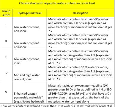
lens material with a water content of 100% would have a Dk of 80 units. Most conventional hydrogels have a Dk range between 10 and 35 units. ISO 18369-1:2006 classifies soft contact lens materials as shown inTable 3.1 to Table 3.3 An example of how the ISO nomenclature is used
Classification with regard to water content and ionic load
Group
suffix Hydrogel material Description
I
Low water content, non-ionic
Materials which contain less than 50 % water and which contain 1 % or less (expressed as mole fraction) of monomers that are ionic at pH 7.2
II
Low water content, non-ionic
Materials which contain less than 50 % water and which contain 1 % or less (expressed as mole fraction) of monomers that are ionic at pH 7.2
III
Low water content, ionic
Materials which contain less than 50 % water and which contain greater than 1 % (expressed as a mole fraction) of monomers which are ionic at pH 7.2
IV
Mid and high water content, ionic
Materials which contain 50 % water or more, and which contain greater than 1 % (expressed as a mole fraction) of monomers which are ionic at pH 7.2
V Enhanced oxygen permeable materials* (e.g. silicone hydrogel)
Materials having an oxygen permeability (Dk) greater than 30 Dk units as defined in 4.4 of ISO 18369-4:2006 (using hPa−1) and that have a Dk greater than that expected on the basis of the materials' water content alone
Low water content is defined as less than 50 % water (< 50 %); mid water content is from 50 % to 65 % water, inclusive (50 % to 65 % water); and high water content is greater than 65 % water (> 65 %). Hence, group suffixes II and IV include all
materials having water content of 50 % or greater.
[image:33.595.142.530.198.560.2]* It is expected that this classification will be further subdivided as more information is gained about the materials in this category.
31
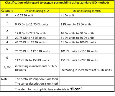
Classification with regard to oxygen permeability using standard ISO methods
Category DK units using hPA Dk units using mmHG
0 < 0.75 Dk unit <1 Dk unit
1
0.75 Dk to 11.75 Dk units 1 Dk unit to 15 Dk units 2
12.0 Dk to 22.5 Dk units 16 Dk units to 30 Dk units 3 22.75 Dk to 45 Dk units 31 Dk units to 60 Dk units 4 45.25 Dk to 75 Dk units 61 Dk units to 100 Dk units 5
75.25 Dk to 112.5 Dk units 101 Dk units to 150 Dk units 6
112.75 Dk to 150 Dk units 151 Dk units to 200 Dk units 7, etc increasing in increments of 37.5
Dk units increasing in increments of 50 Dk units
Note: The prefix description is omitted The series description is omitted
The stem for hydrophilic lens materials is "filcon"
Table 3.2 ISO 18369-1 Classification of soft contact lens materials
Sample: Austrofilcon II 2
Prefix Austro
Stem for hydrophilic lens
materials filcon
Mid water content non ionic II
[image:34.595.129.520.77.405.2]16-30 Dk units 2
Table 3.3 An example of how the ISO nomenclature is used
Bürki (2008) mentions the ACLM Contact Lens Classification for hydrophilic contact lens materials. This includes average Dk values for low, mid and high water content material.
regarding oxygen permeability
32
3.3
Silicone Contact Lenses
Since the oxygen permeability of hydrophilic lenses was limited, attempts were made by the Toyo Company in Japan, Bausch and Lomb in 1979, and Dow Chemical in 1981(Gasson, 2008) to use silicone elastomers, often named silicon rubber, as a material for contact lenses. The remarkable advantage of silicone elastomers was the high oxygen permeability while its hydrophobicity was a severe disadvantage. Silicone elastomer lenses are only commercially available in a limited range from Bausch and Lomb today (Bausch and Lomb, 2015). Heunen (2012) described the method attempted by the manufacturers’ mentioned to overcome this property to make the material usable for contact lenses. The methods to hydrophilize the surfaces were: Plasma discharge, grafting of polyvinyl-pyrrolidone and/or esters and sugars, which decreased the gas permeability of the silicone elastomers.
3.4
Silicone Hydrogel Contact Lenses
The combination of a hydrogel and a silicone elastomer component was first introduced in 1999. In his book “Contact lenses The Story” Bowden (2009) describes the development and the unfulfilled expectation, that this new material will fulfil the criteria for overnight contact lens wear, decreased risk of infection, decreased appearance of epithelial micro cysts, reduced contact lens binding and, last but not least, prolonged comfort. Cast moulding was the initial method of
manufacture of silicone hydrogel contact lenses. The first silicone hydrogel latheable contact lens blanks were commercially available in 2008 and manufactured by Contamac (2008). The essential advantage of the Definitive silicone hydrogel was that after lathe turning and eventually lens polishing a surface treatment was not required. The cast moulded lenses required treatment to achieve wettability. Several techniques to enhance surface properties of contact lens materials were discussed by Keir and Jones (2013).
These were:
Plasma coatings with high refractive index
33 Patented nanoglass technologies
Nonsurface treatment technologies migrating to the surfaces and a long chain, high molecular-weight internal wetting agent based on
polyvinylpyrrolidone
A patented MeniSilk technology to achieve the hydrophilic property of the lenses which is believed to be essential for contact lens comfort.
Delefilcon A daily disposable silicone hydrogel contact lenses contain 33% water and containing an outer surface layer with 80% water. This technique assured high oxygen permeability in combination with good wettability and lubricaton (Pruitt et al., 2012).
3.5
Contact lens manufacturing techniques
The main techniques are as follows: Lathe cut and polished.
Lathe cut with modern computer controlled lathes consisting of air bearing main spindles that produce surfaces which do not need polishing.
Spin casting produces one surface which does not have contact to a mould and probably has the most homogenous surface possible. This concave surface is formed in air by the centrifugal force of the spinning mould. The convex surface will reproduce asperities found in the mould surface and when the xerogel is hydrated the asperities will be larger due to the inherent expansion that occurs.
34
3.6
Soft contact lens fitting
In addition to the tests required for a routine examination of the eye, certain basic procedures need to be carried out for proper fitting of soft contact lenses.
These are: Patient history
Inspection of the visible part of the eye without instruments or magnification For first time wearers, the lid sensitivity can be tested by touching the lower lid and pulling it down a little to assess reaction
Retinoscopy
Subjective refraction
Ophthalmometry (measuring the central corneal curvatures and radii, peripheral corneal radii at an agle of 30°)
Calculation of corneal eccentricity as described by Wilms and Rabbetts (1977) using the formula for the numerical excentricity for 30°:
Ɛ = 2√1 −
𝑟𝑐2𝑟𝑠2
E
quation 135
With these “quasi” tangential radii, the formula in Equation 1 is used to calculate the numerical excentricity for each meridian or for each of the four peripheral
measurements taken.
This method is commonly named the sagittal measurement technique. A slit-lamp inspection of :
Lids, lid margins and eyelashes Bulbar conjunctiva
Careful inspection of the cornea and its layers Conjunctiva of upper and lower lid
Tear meniscus
Tear film and its stability
Fitting instructions issued by the early manufacturers related mainly to movement of the lenses in situ, avoidance of perilimbal impression marks and avoidance of corneal oedema. Wichterle (Gasson, 2008) gave basic fitting instructions with relevant advice. Currently, soft contact lenses are fitted according to
recommendations by the manufacturers. Depending on the total diameter, the BOZR of the lenses need to be between 0.3mm and 1.3 mm flatter than the average
ophthalmometer (keratometer) reading. Although the geometry of contact lenses has seen a major improvement within the last 20 years it is still an underestimated topic (Guillon, 2009).
With the contact lens on the eye, the following should be achieved (Gasson and Morris, 1992):
“good centration of the lens,
complete corneal coverage by the lens,
good visual acuity,
retinoscopy reflex should be crisp and sharp before and after blinking,
vision remains stable on blinking,
over-refraction gives a precise end-point,
refraction correlates with spectacle back vertex power,
keratometer mires stable and undistorted,
no irritation of limbal vessels,
36
In addition, contrast sensitivity (CS) chart testing (Ginsburg, 1984) showed a decrease of CS at high spatial frequencies for soft contact lenses (Thai et al., 2002). Thai et al. believed that the tear break up time could not be the reason for the intermittent blurred vision but did not consider whether the test lenses were steep fitted. Other publications, assuming properly fitted contact lenses, (Guillon et al., 1988) reported better CS with soft contact lenses in comparison with spectacles. Steep, flat, thin and thick soft lenses all produced a decrease in CS (Cox, 1995). Other literature regarding CS with contact lenses (Boxer Wachler et al., 1999) compared different products of soft contact lenses probably assuming a correct fit and found a significant difference between spectacles and CibaSoft lenses at 12 cycles per degree. There is a decrease in CS with standard soft lenses used on a daily wear basis after about 12 months’ use. CS charts were used by the author as a tool to explain why lenses judged “good” by the users required replacement. The results with properly fitted soft lenses presented in Section 7.5 of this thesis are in accord with the author’s experience. The author’s lifetime experience in contact lens fitting confirms a decrease in CS with non disposable contact lenses over a period of 12 months’ daily use. The author further confirms a connection between steep fitted contact lenses and a decrease in CS at high frequencies.
The shape and the power of soft hydrophilic lenses, as labelled in the original packing, are values at ambient room temperature when the lenses are immersed in isotonic saline solution. This ideal contact lens environment is not available for the soft lens when it is placed on the eye.
The ocular environment involves: higher temperature,
slightly changing pH values, different osmotic conditions,
air drying of the tear layer on the anterior lens surface
37
3.7
Contact lens movement on the eye
The difference in cap volume between the contact lens itself and the cap volume of the eye covered with the contact lens played an important role with regard to contact lens movement (Leicht et al., 2005). In this model, Leicht dealt with a horizontal corneal diameter of 11.5mm, a vertical diameter of 10.7mm and a numerical eccentricity of 0.55 with corneal radii from 7.20 to 8.40mm. Leicht calculated an average corneal cap volume of 200mm3 with a standard deviation of 15mm3. They found the average cap volume of a disposable contact lens was 277mm3. Leicht et al. further commented that with the slightest movement of the lens in situ, the
difference in volume dramatically changes and the desired uniform lens dynamic on the eye cannot be expected. It is obvious that the difference in cap volume between lens and the bulbar area covered by the contact lens represents the tear lens. Leicht’s work discussed the volume difference and its change due to lens movement only. An accurate contact lens fit was described as follows (Gasson and Morris, 1992): “1 mm of vertical lens movement on blinking in primary position, a lens lag of up to 1.5mm
on upwards gaze or lateral eye movements.” The movement of today’s thin lenses
on blinking and lag are significantly smaller (Leicht et al., 2005). What keeps the lens in position on the eye?
Forst developed corneal models (Forst, 1981) and postulated, by utilising a simple equation, that deformation of contact lenses developed elastic forces when centring the contact lens again. He compared the cap volumes of the eye covered by a soft contact lens with the cap volume of the soft contact lens. He subtracted the two volumes and calculated the remaining volume between posterior lens surface and anterior surface of the eye covered by the contact lens. Forst found on a “calculated model eye a volume of 0.7mm³” representing the tear layer between contact lens and eye in primary gaze. The volume size influenced lens movement because a “certain
negative pressure” built up due to contact lens movement caused by blinking. Forst suggested that the “volume at least temporarily was closed while the tear liquid
38
volume due to decentration was 0.4 mm3 and resulted in a negative pressure of about 4 Torr.
A major part of lens movement is initiated by the motion of the upper lid. When lid closure starts, the upper lid starts to touch the lower lid from the temporal side towards the nasal side in a “zipper” fashion. The lacrimal gland, due to the squeezing force of the activated upper lid, releases a small quantity of fresh
nutrition-rich and oxygen-rich tears which flush over and under the contact lens. Gas and nutrition are transported via the tears to the corneal epithelium. The old tears are washed away towards the punctum lacrimale. While rigid PMMA and soft HEMA contact lenses are oxygen barriers, modern contact lens materials have better gas permeability and provide more oxygen to the corneal surface. Tear mixing between the posterior lens surface and the front surface of the cornea is of essential
importance (Lin et al., 1999, Guillon and Maissa, 1999). As soon the lids open again, the contact lens is pulled with the opening motion of the upper lid upwards and rotates from nasal to temporal and centres again after the lens reached the highest point.
3.8
Contact lens comfort
Contact lens comfort increased with the use of hydrophilic contact lenses but it remains an issue that causes drop outs of contact lens wearers as discussed by Epstein and Stone (2010). Prolonged research ended in a new silicone hydrogel material, with increased oxygen permeability, which was believed to resolve the problem of microbial keratitis which occurred more frequently in overnight contact lens wearing than with daily warers, which could not be proved. In his editorial article Jones (2013) summarized literature which reported whether the use of silicone hydrogel materials tended to improve the use of contact lenses by
39
40
Chapter 4 - Friction
4.1
Introduction
There are two laws of friction. Firstly, that the frictional resistance is proportional to the load and secondly, that it is independent of the area of the sliding surfaces (Bowden and Tabor, 1950).
The three basic types of friction are: a. Static friction b. Dynamic friction c. Fluid friction
These three types are dealt with in more detail below.
Static friction is defined as the force required to start a solid object moving on a solid surface. Where there is more force required to get the object moving, while maintaining movement, this is termed dynamic friction and this requires less force. It is known that even polished surfaces have microscopic small imperfections which block or hinder movement. Lubricants provide a layer between two surfaces. Any fluid acting as lubricant between two objects will reduce the resistance and will allow easier movement. If two objects separated by a lubricant layer move against each other the frictional properties of the lubricant have a frictional effect against the object only.
The first notes on the topic of friction were found in Leonardo Da Vinci’s Codex-Madrid I dated 1495. Amonton (1699) rediscovered Da Vinci’s two laws of friction:
“The areas in contact have no effect on friction.
If the load on an object is doubled, its friction will also be doubled.”
Charles August Coulomb added in 1785 (Popov, 2009, Bowden and Tabor, 1950):
"Strength due to friction is proportional to compressive force"
Amonton’s laws of friction are described as follows (Zeng, 2013): The friction force is directly proportional to the applied load
The friction force is independent of the apparent contact area”
41
𝜇 =
𝐹𝑟𝐹𝑛 Equation 2
where Fr is the resulting force and Fn is the normal force applied to the surfaces. The
coefficient of friction, µ is a dimensionless number, which can be expressed as a percentage of the applied force. For example, if a coefficient of friction was 0.22 then the resulting force Fr was 22% of the normal force Fn applied. A difference
between µ = 0.2 and µ=0.3 would be 10% of the normal force applied.
Static friction corresponds to the maximum adhering force. Static frictional force is the force required to get a stationary body moving. Human life would not function without static friction. Walking on concrete represents higher friction than walking on ice. Static friction is induced by adhesive forces and ‘toothing’ between surfaces. Related to the contact lens environment, static friction is represented by a contact lens placed on the eye and not moving. To measure static friction the contact lens needs to be moved. The measured initial force required to get an object, i.e. the contact lens, just moving is known as static friction. Dynamic friction is present at the contact surfaces between bodies moving linearly to each other. Coulomb stated that kinetic friction is independent of sliding velocity. Between some material pairings friction increases with speed which is called creep. Sliding or dynamic frictional forces are always smaller than static frictional forces as long the “normal force” Fn remains constant. In other words, more force is required to get a body
moving than to keep it moving. Exceptions to Amonton’s law of friction have been found in many cases (Zeng, 2013).
4.2
Friction and Contact Lenses
42
Analysis of in vivo contact lens motion is necessary to understand the frictional characteristics of contact lens materials and tear fluid. The investigations of Forst (1981) showed that modulus, lens thickness and thickness of tear layer between lens and eye influence lens movement. In human physiology, friction and lubrication play an important role with regard to joints and the flow characteristics of blood vessels. Hip joints and knee joints are surrounded by articular capsules and
lubricated with synovial fluid. Hip and knee joints carry the weight of the body and still need to have low to zero friction. This is achieved by synovial fluid lubrication. Artificial joints suffer from wear and tear but do last some 15 to 20 years (Jin, 2002). Contact lenses float between the tears and the eyelids during blinking. Due to the different lubricating fluids, the differences in force, motion, friction and
lubricating properties of natural and artificial joints cannot be compared with contact lenses in situ. The properties of soft contact lens materials play an important role regarding friction, as discussed in Section 4.4 Polymer friction. Soft contact lenses placed on the eye are surrounded by the tear fluid, acting as a lubricant and the implications of this are considered in Sections 4.3 Fluid friction between solids, 4.5, and 4.7 Tribology.
4.3
Fluid friction between solids
If two solid surfaces, which are separated by a liquid layer, are moved in a parallel motion with the speed “v” against each other, a decrease of speed develops within the separating layer. This is termed the ‘declining shear’ (v/h, where v is the speed and h the thickness of the fluid layer).
To move the surfaces with the speed v against each other, the force (F) is required and results in the pushing tension “τ”. Fluid friction is a function of fluid viscosity only (Cimbala, 2012).
τ = F / A
Equation 343
4.4
Polymer friction
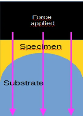
Unlike friction between solids, polymer friction is dependent on speed between substrate and specimen and influenced by intermolecular and surface forces. Zeng (2013) mentions that various forces influence tribological properties. Zeng
mentioned:
van der Waals forces,
forces between two molecules,
electrostatic charged forces between charged molecules and/or surfaces in liquid, which might be attractive or repulsive.
hydrophobic interactions, solvation,
temperature dependent forces hydrogen bonding
Gong et al. (2001) described the dependence between COF and area of contact. She further described the relevance of van der Waals forces and speed. Gong et al’s
work on gel friction was based on a surface repulsion and absorption model that described the difference in contact between two solids and a solid and a water-swollen gel. The smaller elastic modulus of the gel causes the gel to deform even at a low pressure. Additionally, surface tension of a gel helps to make contact with the solid surface. Gel friction depends on the relation between load, elastic modulus and velocity (Gong and Osada, 1998). Gong et al. (2000) described the friction on gels and its dependence caused by pressure, repulsive and attractive forces surface properties of the opposing substrates as an interfacial interaction. They showed that increased attraction causes more friction and is also more dependent on load, with increasing attraction between gel and substrate when the load increases.
A simple comparison made by an anonymous author on the internet explains the issue: “Imagine, something like chewing gum is sticking on the road. It is very lightweight but you already need a quite huge force to remove it (adhesion is
dominating hence the friction coefficient is bigger than 1.0). Now imagine you have
a complete tyre standing on the road. The adhesion force is still the same as on the
chewing gum but your tyre and the car are bigger. Adhesion force is no longer
44
In other words: As soon as the normal force applied to an elastomer is bigger than the adhesive forces between elastomer and substrate, the coefficient of friction decreases. The phenomenon was described in the
dissertation of Deladi (2006), by Stoll and Strangfeld (2012), and in a literature survey by van der Steen (2007) and by Domininghaus (2007). Manufacturers of Polytetrafluoroethylene (PTFE) material made similar statements (Polytetra, 2013, Du Pont, 2013). DuPont (1996) described the frictional properties of PTFE in detail regarding the dependence of normal force and
coefficient of friction. The friction coefficient at room temperature was reported to be 0.3 to 0.4 at 0.0134 kPa, 0.21 at 0.345 to 3.45 kPa, 0.08 at 1.52 to 15.17 kPa at a speed of < 0.00507m/sec (<2ft/min). The friction measurement results with the PTFE used in this work are comparable with these found by Polytetra and DuPont.
4.5
Viscosity
Viscosity defines the thickness of a fluid. A thick fluid has high viscosity and flows slowly while a thin fluid has low viscosity and flow fast. Fluids have a resistance to flow caused by the retarding force of adjacent molecules in the fluid.
4.6
Rheology
Rheology is a field of science related to flow. Flow appears with substances such as liquids, or soft solids, for example muds, suspensions or polymers. Fluids which do not change their viscosity when mechanical properties change, i.e. they are
independent of declining shear, are called Newtonian fluids. Non-Newtonian fluids change their viscosity with the change of mechanical properties, i.e. speed or force. Non-Newtonian fluids are divided into the following groups:
„Virginal Rundstäbe“ manufactured by Polytetra
Moenchengladbach/Germany. Line a: Standard PTFE, line b: Fibreglass enhanced PTFE (Domininghaus, 2007)