TIE ROD ANALYSIS ON RACK AND PINION STEERING SYSTEM
FOR SMALL CLASS VEHICLE
MUHAMMAD SAFFUAN BIN WAHAB
TIE ROD ANALYSIS ON RACK AND PINION STEERING SYSTEM FOR SMALL CLASS VEHICLE
MUHAMMAD SAFFUAN BIN WAHAB
A report submitted
In fulfillment of the requirement for the degree of Bachelor of Mechanical Engineering (Automotive)
Faculty of Mechanical Engineering
UNIVERSITI TEKNIKAL MALAYSIA MELAKA
DECLARATION
I declare that this project report entitled “Tie Rod Analysis on Rack And Pinion Steering
System for Small Class Vehicle” is the result of my own work except as cited in the references
Signature : ….……….
Name : ………..
APPROVAL
I hereby declare that I have read this project report and in my opinion this report is sufficient
in terms of scope and quality for the award of the degree of Bachelor of Mechanical
Engineering (Automotive)
Signature : ….……….
Supervisor’s Name : ………..
DEDICATION
i
ABSTRACT
Nowadays world demands car manufacture to produce a fuel efficient vehicle due to the
consistently tightening regulation for protecting the environment. The use of lightweight
automotive components can reduce fuel consumption and reduce carbon emission. This
project is focuses on the design and material selection of a lightweight tie rod. To design a
lightweight tie rod, a new material that has a lower density is needed. However, this new
material could have a lower mechanical strength and causes the conflicting objectives during
the design process. The objective of this project is to use Ashby’s approach to solve
conflicting objectives during design and material selection process of a lightweight tie rod. A
suitable lightweight material will be determined by using CES Selector software. After the
material was determined, the finite element analysis (FEA) will be conducted. The finite
element analysis (FEA) is carried out to check its maximum stress and deformation. As a
conclusion, trade-offs between low density and good mechanical strength will be considered
ii ABSTRAK
Pada masa kini, dunia menuntut pembuatan kereta untuk menghasilkan kenderaan cekap
bahan api kerana peraturan yang ketat secara konsisten untuk melindungi alam sekitar.
Penggunaan komponen automotif ringan boleh mengurangkan penggunaan bahan api dan
mengurangkan pelepasan karbon. Projek ini adalah memberi tumpuan kepada reka bentuk dan
bahan pemilihan tie rod yang ringan. Untuk mereka bentuk tie rod yang ringan, bahan baru
yang mempunyai ketumpatan yang lebih rendah diperlukan. Walau bagaimanapun, bahan baru
ini boleh mempunyai kekuatan mekanikal yang lebih rendah dan menyebabkan objektif yang
bercanggah semasa proses reka bentuk. Objektif projek ini adalah dengan menggunakan
pendekatan Ashby untuk menyelesaikan objektif yang bercanggah semasa reka bentuk dan
pemilihan bahan proses tie rod yang ringan. Bahan ringan yang sesuai akan ditentukan dengan
menggunakan perisian CES Selector. Selepas bahan ditentukan, analisis unsur terhingga
(FEA) akan dijalankan. Analisis unsur terhingga (FEA) dilaksanakan untuk memeriksa
tekanan maksimum dan ubah bentuk. Kesimpulannya, keseimbangan antara kepadatan rendah
iii
ACKNOWLEDGEMENTS
Alhamdulillah, thanks to Allah s.w.t, the Project Sarjana Muda (PSM) has been completed as
part of the requirements for the award of Bachelor of Mechanical Engineering (Automotive).
Special thanks are dedicated to my supervisor, Mr. Mohd Zakaria Bin Mohammad Nasir for
his support, guidance, and instruction towards this project. Special thanks also to the
Universiti Teknikal Malaysia Melaka (UTeM), especially to the staff of faculty of Mechanical
Engineering Faculty (FKM).
I would also like to thank my family members who have given me support and advice during
the process of completing this project. Last but not least, I would like to thank my fellow
iv
TABLE OF CONTENTS DECLARATION
DEDICATION
ABSTRACT i
ABSTRAK ii
ACKNOWLEDGEMENTS iii
TABLE OF CONTENT iv-v
LIST OF TABLES vi
LIST OF FIGURES vii
LIST OF APPENDICES viii
LIST OF ABBREVIATIONS
LIST OF SYMBOLS xii
CHAPTER
1 INTRODUCTION 1
1.1 Background 1-3
1.2 Problem Statement 3
1.3 Objective 4
1.4 Scope of Project 4
1.5 Report Outline 4-5
2 LITERATURE REVIEW 6
2.1 Tie Rod End Working Mechanism 6
2.2 Type of Lightweight Material 2.2.1 High-Strength Steel
2.2.1.1 Properties High-Strength Steel 2.2.2 Aluminum
2.2.2.1 Properties of Aluminum 2.2.3 Magnesium
2.2.3.1 Properties of Magnesium 2.2.4 Composite
2.2.4.1 Properties of Composite
7 7 7-8 8 8 9 9 9-10 10
2.3 Advantages And Disadvantages Of Lightweight Materials 10-11
2.4 Tie Rod Manufacturing
2.4.1 Advantages and Disadvantages CNC Turning Machine 11-12 11
2.5 CES Selector Configuration
2.5.1 Getting Started 12 13
2.6 CATIA V5
2.6.1 Getting Started
2.6.1.1 Mechanical Design 2.6.1.2 Simulation
13-14 14 14-15
15
2.7 Rack and pinion working mechanism 16
3 METHODOLOGY 17
3.1 Introduction 17
v 3.3 Gather Information
3.3.1 Design Requirement 19 19
3.4 Calculation Of Force Applied To Tie Rod 3.5 Design Analysis
3.5.1 Material Selection 3.5.2 CES Selector 3.5.3 Analysis of Tie Rod
19-20 20 20-22 22-23 24-26
4 RESULT AND DISCUSSION 27
4.1 Preliminary Results
4.1.1 Material Selection Concept 27-30 27
4.2 Calculation Of Force Applied To The Tie Rod 31-32
4.3 Finite Element Analysis (FEA)
4.3.1 Meshing Details 33 33
4.4 Static Finite Element Analysis (FEA) 4.4.1 Displacement Results
4.4.2 Stress Results 4.4.3 Stiffness
33-34 34-36 36-38 39
4.5 Design Requirement For The Light Tie Rod 39-41
4.6 Safety Factor 41-42
4.7 Lightweight Tie Rod Material And A New Design 4.7.1 New Tie Rod Design For Aluminum 6082
4.7.2 Aluminum 6082 Tie Rod Analysis On New Design
42-43 43-44 44-45
5 CONCLUSION AND RECOMMENDATION 46
5.1 Conclusion 46-47
5.2 Recommendation 47
REFERENCES 48-49
vi
LIST OF TABLES
TABLE TITLE PAGE
2.1 High strength steel properties 7-8
2.2 Aluminum properties 8
2.3 Magnesium properties 9
2.4 Composite properties 10
2.5 Advantages and disadvantages of lightweight materials 10-11
2.6 Advantages and disadvantages 11
2.7 Levels in CES Selector 13
3.1 Design requirement 19
3.2 Limit set in CES Selector 22-23
4.1 Criteria set in CES Selector 27-28
4.2 Design requirement 39
4.3 Selection of material 40
4.4 Material properties and safety factor 42
4.5 Aluminum 6082 properties 42-43
vii
LIST OF FIGURES
FIGURE TITLE PAGE
1.1 Mcpherson Suspension system 2
1.2 Tie rod 2
2.1 Tie rod end 6
2.2 Ces selector 12
2.3 Catia v5 14
2.4 Tie rod 3D model 15
2.5 Tie rod analysis 15
2.6 Rack and pinion of steering system 16
3.1 Flowchart for conceptual design 17
3.2 Tie rod end 18
3.3 Fatigue strength vs density 22
3.4 Limitation of material were set 23
3.5 Tie rod 3D model 24
3.6 Analysis and simulation 24
3.7 Meshing of tie rod 25
3.8 Force applied 25
3.9 Von mises stress 26
3.10 Von mises stress with material 26
4.1 Graft yield strength (ksi) against density (lb/𝑖𝑛3) 29
4.2 Graft price (USD/lb) against density (lb/In3) 29
4.3 Graft yield strength (ksi) against price (USD/lb) 30
4.4 Graft young’s modulus (106𝑝𝑠𝑖) against density (lb/𝑖𝑛3) 30
4.5 Steering system 31
4.6 Meshed of tie rod 33
viii
4.8 Displacement cast iron tie rod 35
4.9 Displacement aluminum tie rod 35
4.10 Displacement magnesium tie rod 36
4.11 Von mises steel tie rod 37
4.12 Von mises cast iron tie rod 37
4.13 Von mises aluminum tie rod 38
4.14 Von mises magnesium tie rod 38
4.15 Old tie rod design 43
4.16 New tie rod design 44
4.17 Displacement of aluminum 6082 tie rod 44
ix
LIST OF APPENDICES
NO TITLE PAGE
1 Gantt chart PSM 1 50
x
LIST OF ABBREVIATIONS
CNC Computer Numerical Control
CATIA Computer Aided Three-dimensional Interactive Application
FEA Finite Element Analysis
xi
LIST OF SYMBOLS
m = mass
A = Area
L = Length
𝜌 = Density
F = Force
𝜎𝑒 = Fatigue constrain
M = Material index
ɸ𝐵𝑒 = Shape factor in bending due to stiffness effect
ɸ𝐵𝑓 = Shape factor relates the strength -efficiency
S = Stiffness cross section under consideration
𝑆𝑜 = Stiffness reference solid cross-section
I = Area moment of enertia
𝑀𝑒 = Limiting moment
𝑋𝑜 = output movement
𝑋𝑖 = Input movement
MR = Movement ratio
1 CHAPTER 1
INTRODUCTION
1.1 Background
Nowadays, the use of small class vehicle is highly in demand in Malaysia as it
becomes the most used by the people as transportation in daily life. Most of the automobile
manufacturers are trying to introduce lightweight component. This is due to the improve fuel
consumption and performance because reduction of the weight of a component will reduce the
overall weight of the car.
In this project, a new design of lightweight tie rod is studied. The tie rod is one of the
most elementary parts of a steering mechanism, which has direct and crucial importance in
terms of driving safety. Tie rod is part of steering system which connects center link to the
steering knuckle in conventional suspension system and rack to the steering knuckle in
McPherson suspension system. Tie rod generally gets force from rack and transfer it to the
steering knuckle to turn the wheels. Tie rod is a circular rod with threaded part, Outer end and
2
Figure 1.1:McPherson Suspension system (Patil et al., 2013)
Figure 1.2: tie rod
There have been many cases of lightweight structural design on body and chassis parts
during the past decades (Park, Baek, Seo, Kim, & Lee, 2014). In this case of suspension and
steering systems, there have been many studies on lightweight components, for example
control arm or knuckle, but there were very few cases for the tie rod. This is because the outer
tie rod is relatively much lighter than the other parts. However, along with recent trends, car
[image:18.612.190.473.328.498.2]3
Furthermore, consistent lightweight design is an essential means of extending the driving
range. (Park et al., 2014)
Lightweight automobile parts can be developed by selecting steel substitutes, such as
alloy, magnesium or aluminum. Based on design requirement, optimum selection of steel
substitutes material will be using CES Selector software. The importance of lightweight
design in the automobile industry has increased due to the consistently tightening regulation
for protecting the environment. Other than that, using lightweight component also can reduce
a car’s fuel consumption.
To design lightweight component, one must consider conflicting objectives that may
be associated with it. One of the conflicting objectives is between weight reduction and
strength of the component. In fact, when the course materials with low density are use the
strength will affect. As is known, the strength of a component decides how much load it can
take before it breaks. In this case of lightweight tie rod, strength and mass are conditioning
factor for the fuel efficiency.
1.2 Problem Statement
The problem that brought the idea of tie rod analysis on rack and pinion steering
system for small class vehicle is because the tie rod are susceptible to bending, warping and
breaking. Steel is conventionally used to produce tie rods due to its good mechanical
properties such as high tensile strength and ductility. However, steel has high density and
heavy. So, to minimize the weight of the tie rod, trade-offs must be made between lightweight
and good mechanical strength. A suitable material will be proposed based on Ashby’s
4 1.3 Objective
The objective of this project are to use Ashby’s approach to solve conflicting
objectives during design and material selection process, and to conduct strength analysis of the
tie rod using finite element analysis (FEA).
1.4 Scope of Project
This project will be focused on the finite element analysis (FEA) of the lightweight tie
rod for small class vehicle. Second is to identify what is the conflicting objective. The design
of the component will be carried out and analysis will be done using CATIA software. Based
on the design requirement, optimum selection of lightweight material will be made based on
analysis result using CES Selector software.
1.5 REPORT OUTLINE
In this project, the report will divide into five chapters. Chapter 1 describes about the
introduction of tie rod end. This chapter also reviews about the problem statement of
lightweight and its importance nowadays. Other than that, in this chapter also have objectives
and scope of the project. Next, the Chapter 2 discusses about literature review which is
referring to the journal and the book. From the journal research, we know that type of
lightweight materials and its advantages and disadvantages. Other than that, using lightweight
material can reduce fuel consumption and less carbon dioxide produce. Chapter 3 is a
5
lightweight material will be determined using CES Selector software and the strength will be
tested using finite element analysis (FEA). Next, Chapter 4 show the result and discussion.
Lastly, Chapter 5 is the conclusion of the project and recommendation for the better material
6 CHAPTER 2
LITERATURE REVIEW
2.1 Tie Rod End Working Mechanism
Tie rod end is the part of a tie rod. The tie rod is divided into two sections which is
outer tie rod and inner tie rod. The function of the tie rod is a steering system connects the
center link to the steering knuckle. Tie rod end generally gets force from the rack and transfer
it to the steering knuckle to turn the wheels. The tie rod is a rod with threaded part, outer end
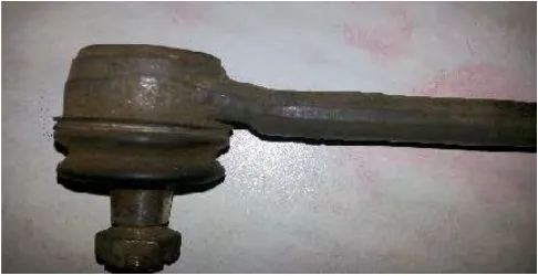
[image:22.612.191.434.444.569.2]and inner end. The tie rod is mostly made up of alloy steel. (Patil et al., 2013)
Figure 2.1:tie rod end
The current trend of the structural design of automobile parts is towards light weight
design, light weight automobile part can be developed by selecting steel substitutes, such as
7 2.2 Type of Lightweight Material
The lightweight materials may also be able to improve vehicle performance, such as
acceleration or ride and handling. Other than that the selected material must have good
mechanical strength to make sure the tie rod end is in good condition for a long period of time.
Failure of tie rod end may cause instability of the vehicle and can cause an accident.
Particularly, lightweight materials can be categorized into four groups (Source: advanced,
lightweight materials development and technology for increasing vehicle efficiency (2008)).
1) High-strength steel
2) Aluminum
3) Magnesium
4) Composites
2.2.1 High-Strength Steel
High-strength steels are commonly used in automotive component because it has good
durability and strength.
2.2.1.1 Properties High-Strength Steel
Table 2.1: High strength steel properties (Source: advanced, lightweight materials
development and technology for increasing vehicle efficiency (2008)).
8
Density, g/𝑐𝑚3 7.87
yield strength, MPa 345
Tensile strength, MPa 483
Modulus of electricity, GPa 205
2.2.2 Aluminum
Aluminum is particularly strong in areas that require cast parts such as engine blocks,
transmission casing and wheel. Nowadays, many cylinder blocks and another part are made
from aluminum. Other than that, aluminum is easily worked using most machining methods
such as milling, drilling, cutting, punching, bending and many more. One of the best known
properties of aluminum is that it is light, with a density one third that of steel, 2.730 kg/𝑚3.
The low density of aluminum accounts for it being lightweight but this does not affect its
strength. Aluminum alloy commonly has a tensile strength of between 70Mpa and 700Mpa.
Unlike most steel grades, aluminum does not become brittle at low temperature. Instead, its
strength increase and at high temperature aluminum strength decrease.
[image:24.612.79.546.71.157.2]2.2.2.1 Properties of Aluminum
Table 2.2: Aluminum properties (Source: aluminum design.net)
Material Aluminum
Density, g/𝑐𝑚3 2.73
yield strength, MPa 265
Tensile strength, MPa 295