Abstract: Demand on permanent magnets increasing rapidly due to greater developments on wind energy, computer hard drives, hybrid electric vehicles, air craft, and mobile phones etc. Nd2Fe14B is one of the promising permanent magnets to achieve
efficient performance in many applications as compared to other magnetic materials. Unfortunately, Nd2Fe14B is considered as
rare earth magnets which are difficult to get rare earth elements. It will be available only in few countries but these are having lots of legal issues. The rare earth elements increase the cost of high performance of permanent magnets and its applications. Hence, making of rare earth free permanent magnets with large energy product is still considered as challenging task. Two phase magnets have achieved a great attention to researchers in the past two decades due to its high value of magnetic energy products and its good magnetic behaviour. By mixing Nd2Fe14B as hard phase
permanent magnets and α-Fe as soft phase, efficient applications can be developed at low cost without compromising its magnetic properties. In this paper, the finite element model with multilayer structure of alternating soft and hard magnetic layers was built to simulate the performance of exchange magnets using ANSYS. The structural modelling of Nd2Fe14B and α-Fe is done separately
and the individual magnetic flux properties are being determined. Then properties of composite magnets were also investigated. The effect of volume fraction and thickness of soft phase magnets was analyzed to find the optimum value of coercivity and magnetic energy. Our simulation results shows that Nd2Fe14B/α-Fe has
excellent magnetic properties and suitable for various practical applications. The results obtained in simulation open new way to optimize the performance of permanent magnets. The economic analysis of the PMSG is carried out as part of this work.
Index Terms: Rare earth magnets, Finite element simulation, Permanent magnets, PMSG.
I. INTRODUCTION
In early 1980, many household appliances, laptop, mobile phones etc were started to manufacture with small in size due to great development in powerful permanent magnets. Also now a day, permanent magnets are more dominant in manufacturing electric motors to propel hybrid vehicles and in wind generators which helps to get low energy consumption, high efficiency and to produce clean environment. The main source of permanent magnets is china which has trouble in satisfying our needs due to legal export restrictions and demand for their own needs. Hence, the cost of permanent magnet (rare earth elements) is increased to very
Revised Manuscript Received on June 05, 2019
S.Sundaramahalingam, Department of Electrical and Electronics Engineering, Mepco Schlenk Engineering College, Sivakasi, India.
S.Arockiaraj, Department of Electrical and Electronics Engineering, Mepco Schlenk Engineering College, Sivakasi, India.
S.Alagammal, Department of Electrical and Electronics Engineering, Mepco Schlenk Engineering College, Sivakasi, India.
N.Vanaja, Department of Electrical and Electronics Engineering, Mepco Schlenk Engineering College, Sivakasi, India.
high value and demand for rare earth magnets increased from 75000 tonnes in 2000 to 123100 tonnes in 2016 [1,2]. Many researchers are proposed a different approach to find more powerful magnets with less neodymium. It is possible to construct more powerful efficient permanent magnets by combining two different materials at the nanometer scale. The value of energy product shows that generation of magnetic field of a certain strength in a magnet. It is often indicated in units of millions of gauss oersteds or MGOe. If the maximum energy product is high, then required size of the magnet is small for a given purpose. Another way to judge the performance of magnets involves measure of coercive field and saturation magnetization. If magnet exhibits large coercive field and saturation, it is considered to be a good performance magnet. Many researchers investigated to find mixtures of magnetic elements to get high value in both saturation magnetization and coercive fields. Over past 30 years, Neodymium iron boron have used in many applications. This type of material has theoretical maximum energy product of 64 MGOe. In 1990, researchers proposed an approach by using two different magnet materials combined together to improve the performance of magnets. It gives better result if it has two different magnetic materials mixed together as compared to either one acting alone. The two magnetic materials, one is having high saturation magnetization and other one has high coercive field.
II. ROLE OF PERMANENT MAGNETS
Over a past few decades, there is significant improvement in wind turbines to use direct drive permanent magnet generator. The main usage of permanent magnets is that it produces magnets on their own without need of any other electricity. Hence it acts as cost efficient, reliable and low maintenance magnets systems for wind turbines. Till 2005, double fed induction generator with gear box is used. As it requires bigger size gear box to run the generator from low speed wind turbine normally from 10-20 rpm to 750 rpm that creates more mechanical problems and requires periodic maintenance. The direct drive permanent magnet generator systems directly connected to the generator comes up without gear box requirement. In next few years, automotive industry requires huge raw materials of rare earth magnets to make hybrid electric vehicles and full electric vehicles which is expected production of about 10 million units in 2026.
Finite Element Modelling and Simulation of
Composite Magnetic Materials Using ANSYS
Fig. 1 : Expected production of Electric vehicle and Hybrid electric vehicle versus permanent magnet demand [1 ]
In order to meet emission standards and climate change, governments has taken steps to introduce electric vehicles to replace conventional internal combustion engine vehicles. According to the survey report, the second largest application of rare earth manet is wind turbines. Due to less efficient of convenienal double fed induction drive. As per Global wind council , wind power installed capacity is expected to reach from 790 GW in 2020 to 1330 GW by 2026 [2,3].
III. BASIC TERMS
The basic terms of magnetic materials [4] are coercivity, remanence, saturation as marked in figure 2.
COERCIVITY(Hc) : In electrical engineering and materials science, the coercivity, also called the magnetic coercivity, coercive field or coercive force, is a measure of the ability of a ferromagnetic material to withstand an external magnetic field without becoming demagnetized. An analogous property, electric coercivity, is the ability of a ferroelectric material to withstand an external electric field without becoming depolarized.
REMANENCE(Br) : Remanence or remanent magnetization or residual magnetism is the magnetization left behind in a ferromagnetic material (such as iron) after an external magnetic field is removed. It is also the measure of that magnetization.
MAGNETIX FLUX : The magnetic flux (often denoted Φ or ΦB) through a surface is the surface integral of the normal component of the magnetic field B passing through that surface. The SI unit of magnetic flux is the weber (Wb), and the CGS unit is the maxwell. Magnetic flux is usually measured with a flux meter, which contains measuring coils and electronics that evaluates the change of voltage in the measuring coils to calculate the magnetic flux.
MAGNETIC FLUX DENSITY (B)
The flux density is the number of magnetic lines of flux that pass through a certain point on a surface. The SI unit is T (tesla), which is weber per square metre (Wb/m2) and the unit in the CGS system is G (gauss). 1 tesla is equivalent to 10,000 gauss.
MAGNETIC FIELD INTENSITY (H)
The Magnetic Field Intensity or Magnetic Field Strength is a ratio of the MMF needed to create a certain Flux Density (B) within a particular material per unit length of that material. H = At/m, ampere-turns per meter. Often, N is used as the number of turns of wire around a core or magnetic material. So the H = N*I/m. UNIT-[ampere-turns per meter, At/m]
PERMEABILITY(µ)
[image:2.595.54.284.47.190.2]The permeability of a magnetic material is a measure of the measure of ease in magnetizing the material. It is the ratio of flux density B, to the magnetizing force,H.
Fig 2 Hysteresis loop
SOFT MAGNET
Soft magnetic materials are easy to magnetize and demagnetize. These materials are used for making temporary magnets. The domain wall movements are easy. It should not possess any void and its structure should be homogeneous so that the materials are not affected by impurities. They have low hysteresis loss due to small hysteresis area. Susceptibility and permeability are high. Coercivity and retentivity values are less. Since they have low retentivity and coercivity, they are not used for making permanent magnets. Magnetic energy stored is less. The eddy current loss is less because of high resistivity.
HARD MAGNET
[image:2.595.314.544.115.295.2]Materials which retain their magnetism and are difficult to demagnetize are called hard magnetic materials. These materials retain their magnetism even after the removal of applied magnetic field. They are used for making permanent magnets. They have large hysteresis loss due to large hysteresis loop area. Susceptibility and permeability are low. Coercivity and retentivity values are large. Magnetic energy stored is high. They possess high value of BH product. The eddy current loss is high. Permanent magnets are considered as hard type magnets[5].
[image:2.595.331.520.612.738.2]IV. FINITE ELEMENT ANALYSIS
Finite Element Analysis (FEA) is a type of computer program that uses the finite element method to analyze a material or object and find how applied stresses will affect the material or design. FEA can help determine any points of weakness in a design before it is manufactured. FEA programs [6,7] are more widely available with the spread of more powerful computers, but are still mostly used in aerospace and other high-stress applications. The analysis is done by creating a mesh of points in the shape of the object that contains information about the material and the object at each point for analysis. In addition to determining the reaction to stress upon an object, FEA can also analyze the effect of vibrations, fatigue, and heat transfer. Commercially, various types of FEM Packages COMSOL MULTI PHYSICS, ANSYS, ANSOFT,MAGNET etc are available. We used ANSYS 19.1 to simulate composite magnets in this paper.
A. ABOUT ANSYS (V 19.1)
ANSYS is a general purpose software, used to simulate interactions of all disciplines of physics, structural, vibration, fluid dynamics, heat transfer and electromagnetic for engineers. ANSYS can work integrated with other used engineering software on desktop by adding CAD and FEA connection modules. Ansys software is used to design products and semiconductors, as well as to create simulations that test a product’s durability, temperature distribution, fluid movements, and electromagnetic properties. Ansys develops and markets finite element analysis software used to simulate engineering problems. The software creates simulated computer models of structures, electronics, or machine components to simulate strength, toughness, elasticity, temperature distribution, electromagnetism, fluid flow, and other attributes.
B. PROBLEM FORMULATION Step 1: Modeling and Analysis
The dimension of the model of Neodymium magnet is taken as 0.5mm*0.2mm*0.1mm.
[image:3.595.309.548.52.175.2]0.5mm
Fig 4. Dimensions of model
Step 2: Material properties
B-H curve is used to show the relationship between magnetic flux density (B) and magnetic field strength (H) for a particular material. B is sometimes called the magnetic flux density or the magnetic induction. Another commonly used form for the relationship between B and H is B = μmH. By plotting values of flux density, (B) against the field strength, (H) we can produce a set of curves called Magnetisation
[image:3.595.308.550.238.406.2]Curves. The shape and size
Fig 6 Modeling of Nd2Fe14B
[image:3.595.311.546.478.662.2]of the hysteresis loop largely depends on the nature of the magnetic material. The choice of a magnetic material required for a particular application often depends on the shape and size of the hysteresis loop.
Fig 5. BH Curve of Nd2Fe14B
A demagnetization curve describes the magnetic qualities of a magnet more completely than a single number like Pull Force or Surface Field. It provides information about the strength of the magnet, how hard it is to demagnetize, and how a magnet’s shape (or use in a magnetic circuit) affects matters.
Fig 5 BH Curve of Ferrite
When using soft ferrite as a magnetic core, since in most cases it will be used with an alternative current, the core may generally be considered at the origin of the B-H curve. When applying an alternating magnetic field to the core, the alternating B-H loop becomes large along the initial magnetization curve. Next,
descriptions will be given for permeability μ using the initial magnetization curve. 0.2mm
[image:3.595.104.248.526.594.2]Step 3: Boundary conditions
The modelling of the hard magnetic material , Neodymium permanent magnet is done in ANSYS Workbench .The dimensions of the material to be tested I taken as 0.5mm*0.2mm*0.1mm.
The boundary condition is provided at the faces.
Step 4: Plot Flux distribution
A. FLUX DISTRIBUTION OF Nd2Fe14B
[image:4.595.310.548.242.443.2]After the modelling of the hard magnet, the whole material is set into an constant enclosure (ie),Air. For this enclosed material a constant magnetic field is applied parallel to the faces of the magnet. For a set time of 1s,the whole magnetic field intensity is obtained.
Fig 7 Flux Distribution in Neodymium
From the obtained result, we can infer that the magnetic field intensity is maximum at the material and minimum in the enclosure. This is the 3D view of the material. This material can be viewed clearly using the WIREFRAME view. The result shows the total flux distribution in the material. This is shown in the figure below,
Fig 8 Flux distribution (Wireframe)
This output is enough to infer that the Neodymium magnet is of high magnetic properties and can provide high flux density. Hence this can be used in the permanent magnet synchronous generators. The main drawback is that the cost of this material is too high and cannot be used commercially. So, a soft magnetic material (ferrite) is added in different proportions and the best proportion efficient in both properties and cost is determined.
Step 5 : Simulation of composite materials
The combining of the materials are done using the ANSYS MECH APDL .The material is made into sheets and combined together into a single material. The combined material is hereby placed in a magnetic field. By determining the value of coercive force for different combinations, the optimum mixture is found.The dimension of the materials are taken as 0.5mm*0.2mm*0.1mm.
A. 100% OF NEODYMIUM
[image:4.595.54.286.256.388.2]For determining the maximum coercive force provided by the material, First total 100% of the material is taken as Neodymium. After the application of flux to the material, the output values of the coercive force are determined. For the whole of neodymium magnet the max value of 1.9627A/m is obtained.
Fig 9. 100% Neodymium
B. 50% Neodymium and 50% Ferrite
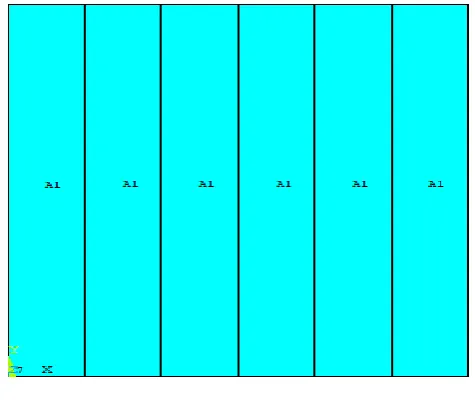
According to the analysis the materials are made into sheets of material. In this we have taken a total of 6 sheets of the materials. For the proportion of 50-50, 3 sheets of Neodymium and 3 sheets of ferrite is taken and flux is provided.
[image:4.595.46.296.493.630.2] [image:4.595.314.529.553.732.2]The magnetic flux at constant room temperature of 40 degrees, is applied to the material. The value of maximum and minimum coercive force is obtained from the analysis.
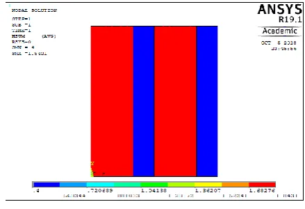
Fig 11 Coercive force of the combination
The obtained maximum value is 1.4325 which is much lesser than the maximum value of Neodymium and hence this combination has low magnetic properties. So this combination is neglected.
C. 60% Neodymium and 40% Ferrite
[image:5.595.311.543.290.437.2]For the next analysis the proportion of 60-40 is taken. For this model 4 sheets of Neodymium and 2 sheets of Ferrite is taken.
Fig 12. 60-40 of Neodymium and Ferrite
The obtained model is subjected to magnetic flux and the coercive force value is obtained.
Fig 13. Coercive force of the combination
In this combination we can obtain the value of coercive force as 1.8431A/m, which is not much less than coercive force value of 100% Neodymium. This combination of the materials can also save a huge amount in its construction.
V. RESULTS AND CONCLUSION
Permanent magnet generator of wind mill needs 500-700 kg/MW of installed capacity. The offshore wind generator requires large size turbines which is likely to increase the requirement of rare earth magnets. From the obtained set of results we can see that the value of coercive force totally depends upon the amount of neodymium present in the total material. The proportion of 60-40 gives an optimum result of about 1.8431A/m which is nearer to 1.9627A/m, the maximum value of neodymium. The value of coercive force determines the magnetic properties of the magnetic material.
So higher the coercive force, higher will be magnetic properties and hence will provide higher efficiency when used as a rotor in PMSM motor.
[image:5.595.50.289.385.544.2]• Cost of Neodymium:-2535 Rs/kg • Cost of ferrite:-200 Rs/kg
Table 1 OUTPUT COMPARISON
% PROPORTIONS COERCIVE
FORCE (A/m)
100% Nd2Fe14B 1.9627
50% Nd2Fe14B& 50% α Fe 1.4325
60% Nd2Fe14B & 40% α Fe 1.8431
100% α Fe 0.4
The output of simulation obtained during the analysis of materials with 60-40% composition is efficient in both cost and properties. In windmill, total weight of Nd2Fe14B used in PMSG is approx. 19.1kg.According to our proposal, if 60-40 % composite material is used, around ₹17500 can be saved.
VI. FUTURE SCOPE
In the growing rate of the nation, production of power at low cost is to be the most important aspect of country’s development. In this regard, the work can be extended by taking experimental results to validate the simulation results. Then the above two materials can be processed in nano scale range to improve an efficiency further.
REFERENCES
1. Roskill. (2016a). Lithium: Global industry, markets and outlook (13th ed.). London, UK: Roskill.
2. Roskill. (2016b). Rare earths: Global industry, markets and outlook (16th ed.). London, UK: Roskill.
3. Kathryn M. Goodenough, Frances Wall and David Merriman, The Rare Earth Elements: Demand, Global Resources and Challenges for Resourcing Future Generations, Natural Resources Research, Vol. 27, No. 2, April 2018
[image:5.595.56.276.603.753.2]5. H.A. Davies, Z.C.Wang, The role of sub-micron grain size in the development of rare earth hard magnetic alloys, Mater.Sci.Eng.A375-37778–83, 2004.
6. R. Skomski, J.P.Liu, D.J.Sellmyer, Quasi coherent nucleation mode in two- phase Nano magnets, Phys.Rev.B: Condens.Matter 60 (10)7359–7365,1999.
7. R. Skomski, Y.Liu, J.E.Shield,
.C.Hadjipanayis,D.J.Sellmyer,Permanent magnetism ofdense-packed nanostructured, J.Appl.Phys.107,p.09A739-1–09A739-3, 2010.
AUTHORSPROFILE
Mr.S.Sundara Mahalingam graduated in Electrical and Electronics Engineering from SSN College of Engineering, Chennai, Tamilnadu, India in 2010. In 2012, he received Master of Engineering (M.E) degree in High Voltage Engineering from the College of Engineering Guindy, Anna University, India. He had undergone project internship training at Crompton Greaves LTD, Mumbai. He had 6 years of teaching experience and currently he is working as an Assistant Professor in the Department of Electrical Engineering at Mepco Schlenk Engineering, Sivakasi, Tamil Nadu, India. Now, he is pursuing his research in the field of High Voltage Engineering under Anna University, Chennai, India. His research activities are focused on FEM, Nano composite magnetic materials.
Mr.S.Arockiaraj graduated in Electrical and Electronics Engineering from Francis Xavier Engineering College, Tamilnadu, India in 2009. In 2013, he received Master of Engineering (M.E) degree in Power System Engineering from the College of Engineering Guindy, Anna University, India. He had 6 years of teaching experience and currently he is working as an Assistant Professor in the Department of Electrical Engineering at Mepco Schlenk Engineering, Sivakasi, Tamil Nadu, India. He has published many international journals.
Mrs. S.Alagammal graduated in Electrical and Electronics Engineering from Thiagarajar College of Engineering, Madurai, Tamil Nadu, India, in 1995. In 2008, she received Master of Engineering (M.E) in Power Electronics and Drives from College of Engineering, Guindy, Anna University (AU), Chennai, India. She had 8 years of teaching experience in Adhiparasakthi Engineering College, Melmaruvathur. From 2009 to 2015, she was an Assistant Professor (AP) in Electrical Engineering Department at Mepco Schlenk Engineering, Sivakasi, Tamil Nadu, and India. Since 2016, she has been an AP (Sr. grade) in the same college. Now, she is pursuing her research in the domain of power electronics applications in solar energy under AU, Chennai, India. Her research interests are on applications of power electronics converters in PV systems, MPPT controller using artificial intelligence techniques.
![Fig. 1 : Expected production of Electric vehicle and Hybrid electric vehicle versus permanent magnet demand [1 ]](https://thumb-us.123doks.com/thumbv2/123dok_us/8200361.260622/2.595.331.520.612.738/expected-production-electric-vehicle-hybrid-electric-vehicle-permanent.webp)