Ames Laboratory Publications
Ames Laboratory
5-15-2002
Permanent magnet array for the magnetic
refrigerator
S. J. Lee
Iowa State University
J. M. Kenkel
Iowa State University
Vitalij K. Pecharsky
Iowa State University, [email protected]
David C. Jiles
Iowa State University, [email protected]
Follow this and additional works at:
http://lib.dr.iastate.edu/ameslab_pubs
Part of the
Electromagnetics and Photonics Commons
The complete bibliographic information for this item can be found at
http://lib.dr.iastate.edu/
ameslab_pubs/151
. For information on how to cite this item, please visit
http://lib.dr.iastate.edu/
howtocite.html
.
Permanent magnet array for the magnetic refrigerator
Abstract
Recent research into the development of magnetic refrigeration (MR) operating at room temperature has
shown that it can provide a reliable, energy-efficient cooling system. To enhance the cooling power of the
magnetic refrigerator, it is required to use a magnetic refrigerant material with large magnetocaloric effect
(MCE) at the appropriate temperature. Most advanced magnetic refrigerant materials show largest MCE at
high applied magnetic fields generated by a superconducting magnet. For application of MCE to air
conditioners or household refrigerators, it is essential to develop a permanent magnet array to form a
compact, strong, and energy-efficient magnetic field generator. Generating a magnetic field well above the
remanence of a permanent magnetmaterial is hard to achieve through conventional designs. A permanent
magnet array based on a hollow cylindrical flux source is found to provide an appropriate geometry and
magnetic field strength for MR applications.
Keywords
Magnetic fields, Permanent magnets, Magnetic materials, Refrigerators, Magnetoresistance
Disciplines
Electromagnetics and Photonics
Comments
The following article is from
Journal of Applied Physics
91 (2002): 8894 and may be found at
http://dx.doi.org/10.1063/1.1451906
.
Rights
Copyright 2002 American Institute of Physics. This article may be downloaded for personal use only. Any
other use requires prior permission of the author and the American Institute of Physics.
Permanent magnet array for the magnetic refrigerator
S. J. Lee, J. M. Kenkel, V. K. Pecharsky, and D. C. Jiles
Citation: Journal of Applied Physics 91, 8894 (2002); doi: 10.1063/1.1451906 View online: http://dx.doi.org/10.1063/1.1451906
View Table of Contents: http://scitation.aip.org/content/aip/journal/jap/91/10?ver=pdfcov Published by the AIP Publishing
Articles you may be interested in
A feasible approach for preparing remanence enhanced NdFeB based permanent magnetic composites J. Appl. Phys. 109, 07A710 (2011); 10.1063/1.3551744
Studies of strong magnetic field produced by permanent magnet array for magnetic refrigeration J. Appl. Phys. 95, 6302 (2004); 10.1063/1.1713046
Plasma sprayed Nd–Fe–B permanent magnets J. Appl. Phys. 93, 7987 (2003); 10.1063/1.1558590
Pulsed field magnetometery for high coercivity permanent magnets J. Appl. Phys. 93, 8546 (2003); 10.1063/1.1557763
Crystal orientation control of multipole ring magnets for a surface permanent magnet rotor J. Appl. Phys. 93, 8671 (2003); 10.1063/1.1541655
Permanent magnet array for the magnetic refrigerator
S. J. Lee,a)J. M. Kenkel, V. K. Pecharsky, and D. C. Jiles Ames Laboratory, Iowa State University, Ames, Iowa 50011
Recent research into the development of magnetic refrigeration共MR兲operating at room temperature has shown that it can provide a reliable, energy-efficient cooling system. To enhance the cooling power of the magnetic refrigerator, it is required to use a magnetic refrigerant material with large magnetocaloric effect 共MCE兲 at the appropriate temperature. Most advanced magnetic refrigerant materials show largest MCE at high applied magnetic fields generated by a superconducting magnet. For application of MCE to air conditioners or household refrigerators, it is essential to develop a permanent magnet array to form a compact, strong, and energy-efficient magnetic field generator. Generating a magnetic field well above the remanence of a permanent magnet material is hard to achieve through conventional designs. A permanent magnet array based on a hollow cylindrical flux source is found to provide an appropriate geometry and magnetic field strength for MR applications. © 2002 American Institute of Physics. 关DOI: 10.1063/1.1451906兴
INTRODUCTION
The magnetocaloric effect 共MCE兲is the heating or the cooling of magnetic solids in a varying dc magnetic field. When an externally applied magnetic field increases, the spin entropy in the ferromagnetic material is reduced due to the alignment of magnetic moments with the direction of the magnetic field. The conservation of total entropy in an adia-batic process leads to the enhancement of lattice entropy, thus raising the temperature of the material. The MCE can be determined from the direct, magnetization or heat capacity measurements. The temperature change ⌬Tad is obtained from the measured data.1Usually the maximum MCE occurs for ferromagnetic materials at their Curie temperatures Tc because the spin entropy change is maximum at Tc. The search for magnetic materials showing large MCE has in-creased because they can be used as solid magnetic refriger-ant materials for magnetic refrigerators共MRs兲.2–5A MR can be used to replace the standard gas-compression refrigerator because it offers an energy-efficient and environmentally clean operation.
Zimm et al.6 have demonstrated a reciprocating mag-netic refrigerator working near room temperature using Gd(Tc⫽294 K) in a magnetic field between 1.5 and 5 T. In the MR system, two beds containing a spherical powder of Gd move in and out of high magnetic field volume at low frequency. The magnetic field has been provided by a liquid He-immersed superconducting magnet. In this system water was employed as the heat transfer fluid. The temperature changes due to MCE were 4.5 and 11 K when the magnetic field changes were 1.5 and 5 T, respectively. Using supercon-ducting magnets for household MR is unrealistic and the conventional permanent magnet arrangements do not provide the necessary field strengths for MR. Therefore it is impor-tant to develop a permanent magnet array which can provide magnetic fields typically above 1.5 T for advanced magnetic refrigerant materials such as Gd5(SixGe1⫺x)4 alloys.3,4
Bo-higas et al.7employed permanent magnets arranged in a con-ventional design to generate a magnetic field in a rotary MR. Two NdFeB permanent magnets 共50 mm⫻50 mm⫻25 mm兲 displaced parallel to each other produced a uniform magnetic field of 0.3 T in the region between the two permanent mag-nets. ⌬Tad was 1.6 K for Gd ribbon attached on a disk and rotating in a magnetic field of 0.3 T.
MAGNETIC FIELD SOURCE
Usually the magnetic refrigerant materials are either packed in a magnetocaloric bed as small spheres6 attached around a disk as a ribbon7 or separated in a pile of thin, equally spaced sheets.8Along with a large MCE magnitude, a strong applied magnetic field is critical to the efficiency of MR. The simplest permanent magnet design would be to place two rectangular-shaped permanent magnets parallel to each other separated by a certain distance, but this does not provide the necessary field strength for MR.7To enhance the magnetic flux density, soft magnetic material with a high permeability can be attached to both ends of the permanent magnets, therefore becoming a yoke-shaped permanent magnet.8 These are easily fabricated but the generation of magnetic fields well above the remanence of the permanent magnet material is difficult.
However it has been shown that a magnetic field beyond the remanence of a permanent magnet material can be achieved by arranging permanent magnet segments in the form of hollow cylindrical shells.9,10The basis for the design of a hollow cylindrical permanent magnet array 共HCPMA兲 originates from the rotation theorem of Halbach.11Using the rotation theorem, the magnetization vectors of each perma-nent magnet segment can be positioned to produce a coher-ent magnetic flux density in the ccoher-enter of the HCPMA. The analytical formula for the maximum magnetic flux density in the center of the ideal permanent magnet arrays is given by
B⫽BRln共ro/ri兲, 共1兲
where riand ro are the inner and outer radii, respectively. In practical applications, the continuous structure is divided a兲Author to whom correspondence should be addressed; electronic mail:
JOURNAL OF APPLIED PHYSICS VOLUME 91, NUMBER 10 15 MAY 2002
8894
0021-8979/2002/91(10)/8894/3/$19.00 © 2002 American Institute of Physics
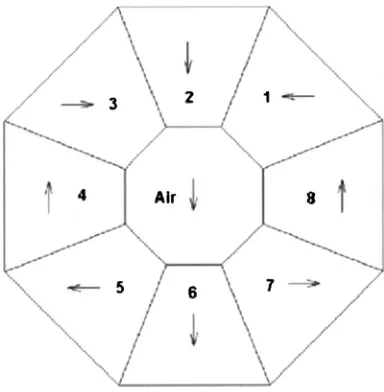
into a smaller number of segments that are joined together. A HCPMA with eight segments for MR applications may be favorable over a larger number of segments because it is easy to fabricate while losing only 10% of the magnitude of B compared with the value expected on the basis of Eq. 共1兲. Figure 1 shows the cross section of a HCPMA with eight permanent magnet segments. The directions of magnetiza-tion vectors are indicated as arrows. As shown in Fig. 1, the air gap is enclosed by eight permanent magnet segments. Access to the magnetic field in the air gap is possible only through the top of the HCPMA.
MODIFIED HCPMA FOR A ROTARY MR SYSTEM
For a reciprocating MR system, refrigerant materials are moved alternately in and out of the bore of the magnet using an air cylinder drive.6 The temperature of the refrigerants increases when the refrigerant materials enter the magnetic field and decreases as they exit the magnetic field. In this scheme, a modified HCPMA without a slot may be used.12 But for a rotary MR system where the refrigerant materials in the beds rotate in a circular path,7a slot is required to access the air gap where the magnetic field is the strongest. If the slot height is too large, then the magnetic flux lines will be distorted significantly in the air gap. Slot widths smaller than the size of the refrigerant material would prevent its access to the magnetic field. Figure 2 shows the geometry for the modified HCPMA with a slot and the arrows indicate the direction of magnetization vectors of each segment. Soft magnetic materials共indicated by SM in the center兲were used for focusing and enhancing the magnetic field. The thin bar-shaped SM materials attached to the left were used for re-ducing the magnet flux leakage. This geometry looks like a C-shaped yoke and provides easier access for the magneto-caloric beds. The cross sectional dimensions of the array are 114⫻128 mm2 and the air gap height is 12.7 mm. NdFeB(BR⫽1.2 T) was used as a permanent magnet and FeVCo was used as a soft magnetic material for the finite
element calculations. The magnetic field at the center of the air gap was about 1.9 T and was homogeneous.
The magnetic flux lines when Gd is located in the air gap are shown in Fig. 3. The cross sectional dimensions of Gd are 15.2⫻10 mm2. The magnetic field is also homogeneous, and the magnitude of magnetic flux density within the Gd sample increased from that without a sample. The measured magnetization curves ( M – H) of Gd at 290 and 310 K were incorporated into the finite element calculation for the mag-netic flux density. The magnitudes of the magmag-netic flux den-sities within the Gd sample were 2.5 and 2.25 T for 290 and 310 K, respectively. The magnitude of B at 310 K was less than that at 290 K because the magnetic moments of Gd become weak above Tcwhich is at 294 K.
SUMMARY AND CONCLUSION
[image:5.612.78.270.51.247.2]For the application of MCE to magnetic refrigerators, a strong magnetic field is required because MCE increases as
[image:5.612.358.517.51.229.2]FIG. 1. Permanent magnet array with eight segments. Arrows indicate the directions of magnetization vectors of each segment.
[image:5.612.340.535.570.731.2]FIG. 2. A modified permanent magnet array with seven permanent magnet segments and soft magnetic materials. The direction of magnetization vec-tors of permanent magnets is indicated by arrows. The direction of magnetic field in the pole gap of the modified permanent magnet array points down-ward. The shaded areas represent soft magnetic materials. The cross sec-tional dimensions of the array are 114⫻128 mm2and the air gap height is 12.7 mm.
FIG. 3. The magnetic flux lines in the modified permanent magnet array where Gd is located at the center of the array.
8895
J. Appl. Phys., Vol. 91, No. 10, 15 May 2002 Leeet al.
the magnitude of applied field increases. Permanent magnets are ideal for MR applications due to their compact size, large remanence, and zero power consumption requirements, but conventional permanent magnet designs cannot produce a sufficiently high magnetic field so that the magnetic induc-tion is well above the remanence of the permanent magnet materials. Therefore a modified permanent magnet array with a slot for refrigerants was designed based on the rotation theorem of Halbach. The magnetic field at the air gap was 1.9 T. This design is appropriate for a rotary magnetic refrig-erator and provides a larger magnetic field than conventional permanent magnet designs.
ACKNOWLEDGMENT
This research was supported by the U.S. Department of Energy, Office of Computational and Technology Research Laboratory Technology Research Program.
1K. A. Gschneidner, Jr. and V. K. Pecharsky, Mater. Sci. Eng. 287, 301 共2000兲.
2
V. K. Pecharsky and K. A. Gschneidner, Jr., Phys. Rev. Lett. 78, 4494
共1997兲. 3
V. K. Pecharsky and K. A. Gschneidner, Jr., Appl. Phys. Lett. 70, 3299
共1997兲. 4
F. W. Wang, X. X. Zhang, and F. X. Hu, Appl. Phys. Lett. 77, 1360共2000兲. 5H. Wada, Y. Tanabe, M. Shiga, H. Sugawara, and H. Sato, J. Alloys
Compd. 316, 245共2001兲.
6C. B. Zimm, A. Jastrab, A. Sternberg, V. Pecharsky, K. Gschneidner, Jr.,
M. Osborne, and I. Anderson, Adv. Cryog. Eng. 43, 1759共1998兲. 7
X. Bohigas, E. Molins, A. Roig, J. Tejada, and X. X. Zhang, IEEE Trans. Magn. 36, 538共2000兲.
8
W. Dai, B. G. Shen, D. X. Li, and Z. X. Gao, J. Magn. Magn. Mater. 218, 25共2000兲.
9
H. A. Leupold and E. Potenziani II, IEEE Trans. Magn. 23, 3628共1987兲. 10H. A. Shute, J. C. Mallinson, D. T. Wilton, and D. J. Mapps, IEEE Trans.
Magn. 36, 440共2000兲. 11
K. Halbach, Nucl. Instrum. Methods 169, 1共1980兲.
12S. J. Lee and D. C. Jiles, IEEE Trans. Magn. 36, 3105共2000兲.
8896 J. Appl. Phys., Vol. 91, No. 10, 15 May 2002 Leeet al.