Abstract— Smart Grids are getting a reality all around the world. Currently, the explore efforts for the introduction plus deployment of those grids are particularly targeted on the improvement of the sector of Smart Metering. This rising application calls for the use of technologies to get right of entry to the tremendous variety of points of supply (PoS) existing inside the grid, masking the Low Voltage (LV) section with the bottom feasible fees. Power Line Communications (PLC) has been appreciably used in energy grids for an expansion of functions and, of past due, has been the focal point of renewed interest. PLC is really nicely suitable for brief and inexpensive pervasive deployments. Yet, no LV grid is the same in any strength organization (application), and the particularities of each grid evolution, structure, circumstances and substances, makes it a undertaking to send Smart Metering systems with PLC advancements, with the Smart Grid as a last reason. This paper focused on the advancement of Smart Metering systems, together with the development of PLC technology until each world have converged to assignment PLC-enabled Smart Metering networks towards Smart Grid. This paper creates recommendations over a hard in addition to quick of key variables of PLC Smart Metering system sending dependent on the know-how collected on real subject; and introduces the destiny challenges of those networks of their evolution closer to the Smart Grid.
Keywords— Design-for-testability (DFT), PLC at ICs, PLC receiver, power line communications (PLCs).
1. INTRODUCTION
The Smart Grid is predictable at present as a Revolutionary concept that, regardless of a number of the troubles related to the shortage of compromise over a unique plus closed description, is in the technique of being carried out in many strength grids everywhere in the international. Within the factors that can be dyed as standing inside the consensus of the utility network within the Savvy Grid definition, we find the expansion of most recent advances of hardware, and Information and communications technologies (ICTs) carried out on the distribution grid electricity belongings, to get a better power supply based on far off tracking and metering of the present belongings, a better adjustment between strength manufacturing and intake, the optimization of operation reaction times, and the improvement within the grid technical losses. Smart Metering is the application that is experiencing more guide both from the enterprise and utilities, that discover within the deployment of clever meters an plausibility to assemble the standards for a greater degree Smart Grid, while getting a couple on the spot benefits got from the funds and modern
Revised Version Manuscript Received on 05 April, 2019.
G. Sahithi, PG Scholar, Deparment of ECE, Sreenidhi Institute of Science and Technology, Yamnampet, Ghatkesar, Ranga Reddy, Telangana. India.
Dr. Asha Devi, Professor, Sreenidhi Institute of Science and Technology, Yamnampet, Ghatkesar, Ranga reddy, Telangana. India.
open doors based at the ongoing get passage to customers' cunning meters. PLC is a broadcast communications period with a protracted records and way of life in power businesses, with a wide extent of utilizations, types and usage. The conjunction of the Smart Metering in addition to PLC advances has been featured from the first actual thought of PLC systems, and increasingly in the ultimate many years. The projection of PLC into the Smart Grid is an issue that has been specifically tended to perceiving in PLC "a magnificent and develop time that could help a wide sort of bundles from the transmission feature to the dispersion perspective and furthermore to and in the local". From an essentially scholastic frame of mind, the advancement of the subjects concentrating the eye of scientists on PLC has pursued the antiquated course of big business intrigue (high voltage (HV)- lines spread, metering and control, medium voltage (MV)- condition, broadband (BB) get admission to, and in-nearby correspondences). Of past due, Smart Grids have concentrated on a noteworthy piece of the eye of both industry and academic around the world, through a progression in which Smart Metering has been the focal point of the interest. The PLC composing is expressly made out of insightful papers focused on low degree explicit data of PLC advancement. Uproar, channel characteristics, guideline plans, MAC structures,and numerous others are fundamentally ensured with the guide of scholastic specialists. With this data, PLC age has figured out how to advance and advance into unprecedented device details which have in the long run been completed on genuine region to offer real contributions. Be that as it may, the utility of any PLC age to the quality matrix isn't constantly direct. The so-known as "PLC expectation to learn and adapt" won't be perfect for a power association that desires to use PLC to set up a supplier orientated PLC gadget. Power framework explicit data are not routinely found in the normal clinical composition and even in the quality business related affiliations (e.g., [11]). Thusly the sending of PLC courses of action is commonly a field in which utilities can't be without inconvenience helped, as no longer various in vogue open particular references may be found. It is the supposition of the makers that this condition is the basic driver of the lazy and unequal determination cost of PLC developments inside the undeniable utilities. The clarifications behind these non-existing trendy organization pointers envelop intentions together with utility of the time on genuine frameworks being far from instructors, vitality network being a transmission
A PLC Receiver Design for Testability
isn't constantly reachable to a large portion of the general population (aside from the in-home fragment), what's more, PLC advancement not being a customary transmission media for media transmission geniuses. This paper will make a commitment to clear up those elements, displaying tips for the arrangement of Smart Metering frameworks.
Power Line Communications (PLCs)
Power follows had been at first contrived to transmit electric fueled power from a little scope of assets (the turbines) to a monstrous amount of sinks (the buyers) inside the recurrence scope of 50-60 Hz. It is a reality that power transmission towers and highlights are probably the sturdiest structures at any point constructed. Verifiably, the PLC time has controlled applications yet at this point we are seeing its likelihood being acclaimed all around as a high method of whole deal data discussion [1]. With the unavoidable entry of broadband access, the interest for sending advanced voice, video and Internet insights inside the local will increment always. While retrofitting the houses and neighborhoods with extraordinary wires is one choice, it's miles expensive and tedious. PLC Technology allows the utilization of the present and immense quality dispersion foundation to offer over the top speed organizing skills nearby a wide range of favors.
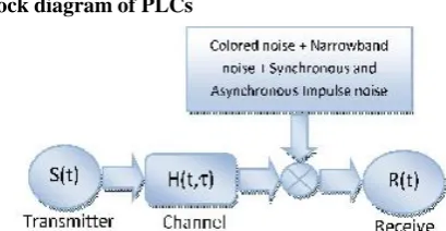
[image:2.595.58.263.360.466.2]Block diagram of PLCs
Figure 1: General block diagram for PLC systems.
2. LITERATURE SURVEY
In recent years, the advancement in broadband over power line technology and its perceived potential has lead to several studies been performed to determine its feasibility for use for communications in several systems, such as airplanes, cars, airport lighting systems, ships and space shuttles, that have pre-existing power cables. Our social affair anticipated PLC in ICs to lessen the stick check, measure, and in this manner the cost of a chip at first plus later to build the channel limit with respect to the different parallel sweep plan. To catch up the proposition, we researched a few significant subjects for PLC in ICs, as well as explored them quickly as pursues. We quantified the proliferation misfortune from a center influence supply stick to an on-chip center point of a PDN of a cold Pentium 4 bite the dust (65 nm adaptation). The biggest pass band was watched ∼2 GHz over a 200-MHz band, plus the way misfortune increments over 40 dB past 2.5 GHz. Different estimations were done on three unique examples of cold 45-nm Core 2 Duo processors as well as two arbitrarily selected areas on the PDNs. The found the middle value of exchange work indicates slender sporadic pass groups, where as regards 5%∼7% of the information flag experiences the PDN. We saw that there is little association pointed the pass
Core 2 Duo processors. We proposed the use of ultra wideband (UWB) in addition to coordinate progression code division various passage (DS-CDMA) correspondence headways to avoid the frustrating of data movements in low frequencies at packs in addition to PDNs in addition to increase the SNR.Contrasted and the conventional thin band correspondence frameworks UWB flagging has a few favorable circumstances, for example, high information rate, little normal power, and basic RF hardware [11]. Shannon's theory communicates that as far as possible is given as B×log2 (1+SNR), where B is the information transmission [12]. As the exchange speed is much greater (on the solicitation of a couple of gigahertz) for UWB than a limited band banner, the SNR can be significantly more diminutive for UWB to achieve comparative data rate.The DS-CDMA improvement doles out a codeword to each piece of data called spreading, and symmetrical code words are alloted to various clients or power pins for the PLC in ICs to help different channels. The spreading errand tends to 1 bit of information as a development of parallel heartbeats spread over a codeword, which expands the beat abundance rehash. The advantage of spreading is the preparing expansion, which is 10 × logs (spreading_ factor) in decibel. For instance, the spreading factor for 4-bit code words is 4, which yields managing extension of 6 dB, or becomes the SNR by 6 dB. We moreover broke down the appearing of I/O cushions and PDNs, in addition to evaluated the execution of the anticipated PLC systems [13] [14].
transmission medium, control line has particular preferred standpoint in setting up a system without extra line 6 establishment and existing advanced gadgets, including home apparatuses and data gadgets, at an exceptionally minimal effort. Numerous applications are working at fast and a fixed association is regularly favored. On the off chance that the power utilities could supply correspondence over the electrical cable to the clients it could make a colossal leap forward in correspondence. Each family unit would be associated whenever and administrations being given at constant. Utilizing the electrical cable as a correspondence medium could likewise be a financially savvy path contrasted with other framework since it utilizes a current foundation, wire exists to each family unit associated with the electrical cable system. Then again, gadget control in home mechanization still can be provided by electrical cable itself. So PLC quickly turns into a prevalent answer for set up private system. Concerning the previous, one ought to think about that the objectives are regular houses, adjusted when clients have a mishap prompting incapacity or when they get more established. Flag quality or flag constriction in home electrical line is vital for structure of home mechanization correspondences circuits. PLC correspondence signals through principle electrical cables are transmitted from a piece of the home and got at the opposite side. Estimations are done between general divisions of a home, for example, kitchen, rooms, lounge, corridor, and restroom, and so on. Connectors are utilized to convey electrical cables in the divisions of homes. Connectors are set at the divider between two neighbor divisions at home. So control is conveyed through these connectors to each division. Connectors are instigated an extra weakening.
Power-line distances calculated for signal attenuations given are between 6–30 m.
Design for Testability Using Scan path Techniques for Path-Delay Test and Measurement
This paper illustrates a fresh flip-flop design which is exploited in performing interior path-delay test plus dimension with scan path performance: Also illustrated is the intend for a boundary-scan cell that enables input/output delays to be considered [3]. The paper contains a real-life submission illustration.
Conditionally Robust Two-Pattern Tests and CMOS Design for Testability
The idea of a restrictively hearty two-design test for testing stuck-open transistor blames in CMOS gates is presented. Such a test is restrictively peril free; i.e., the progress won't deliver a perilous yield gave a (partial) request is forced on the time moments at which the parts of the information design experience change. Two wellsprings of the presence of such a halfway request are distinguished:
(I) when a lot of transistors is constrained by a similar rationale flag, the emblematic format (routing) data gives the learning of such a halfway request;
(ii) Multi pattern tests, which might be important to test implanted CMOS doors, can be viewed as two example tests with a forced incomplete request. Calculations are given to (a)
decide if a two-design test is restrictively hazard free under a given halfway request and (b) figure insignificant Cardinality fractional requests which, when forced on a change, make it restrictively hazard free.
3. PROPOSED SYSTEM
The anticipated chip PLC authority gets the data superimposed on electrical links, in addition to the data, (for instance, channel test data) is sent from a test instrument. In this way, the transmitter for the PLC beneficiary is an outside instrument as opposed to the one on a similar chip. The gatherer was composed in CMOS 0.18-μm improvement with a supply voltage of 1.8 V. It includes three structure squares, and this area delineates the structure of each structure square.
A. Block Diagram
[image:3.595.330.530.296.384.2]A block outline of the arranged PLC collector is revealed in Fig. 2.
Fig. 2. Square outline of the proposed PLC receiver The proposed PLC recipient comprises of three hinders, each having a similar supply voltage (VDD+vdd(t)). The primary square is an estimation shifter, which chops down the dc estimation of the pennant superimposed on the supply voltage. The estimation moved pennant is set up by the ensuing ruin, a standard extractor, which improves the flag and changes over it to a differential flag. The reason restorer, which is a differential Schmitt trigger, recuperates technique for thinking respects from the differential pennant. The course of action and activity of each square is explained underneath.
B. Level Shifter
The measurement shifter revealed in Fig. 3 can be pleasured as a typical source intensifier with diode-associated trouble as, in which the enhancer input is fixed to a tendency voltage Vbias.
[image:3.595.336.547.597.831.2]constrained on the supply voltage VDD to the yield while chopping down the dc voltage measurement of the flag to 0.5VDD. To spread the information standard superimposed on the supply voltage to the yield, the yield should be delicate to supply voltage collections. Constantly end, ignoring a customary intensifier structure, the power supply rejection extent (PSRR) of the measurement shifter ought to be set to near nothing. The PSRR of the conventional source enhancer with the entryway of M1 as the information is portrayed as the degree of the voltage gain from the promise to the voltage gain from the supply voltage of each structure square.
---1
Where Av is the little flag voltage extend from the information (i.e., the entryway ofM1) to the yield of the amplifier, in addition to AVDD is the little flag grow from the power supply to the yield. Av is gained as
---2
Where gm1andgm2are the transconductances ofM1 andM2, respectively. AVDD is obtained as in (3) and becomes 1 disregarding the channel span modulation
---3
Along these lines, the PSRR of a widespread source amplifier is expressed as
---4
The transconductance of a MOS transistor is
---5
By substituting (5) in (4), the PSRR becomes
---6
Condition (6) shows that the PSRR can be brought some place around setting (W/L)1 little, (W/L)2 wide, the overdrive voltage of M1 little, and the overdrive voltage of M2 enormous. This proposes the propensity voltage and the W/L degree of M1 ought to be set to near nothing, while operatingM1 in submersion. Since the ideal dc voltage level at the yield of the distinctive circuit is 0.5 VDD, the condition sets the overdrive voltage of M2. A general W/L degree forM2increases the present ID, thusly it is a tradeoff between low-control dispersing and low PSRR. The overdrive voltage (VGS– VTH) of M1 is set to a close-by irrelevant (=0.08 V) for the proposed estimation shifter and that for M2 extensive (=0.373 V). In like manner, (W/L)1 is set practically nothing (=22.2), and (W/L)2 all around wide (=55.6). The resultant PSRR for the estimation shifter is 1.3 (or 2.27 dB), which is minimal separated and a standard estimation of essential enhancers going from 65 to 80 Db [15].
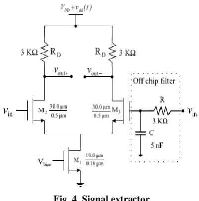
C. Signal Extractor
The information indication of the banner extractor is the information banner offset with 0.5 VDD, notwithstanding the
[image:4.595.329.530.99.302.2]taking out the dc balance voltage. The banner extractor revealed in Fig. 4 is a blunder enhancer, in which one data is identified with a RC low-pass channel.
Fig. 4. Signal extractor
The low-pass channel intends to isolate the dc estimation of the flag. The differential enhancer disposes of the typical mode banner of the two data sources or the dc regard. It also changes over a single completed commitment to a differential yield pair. The voltage expansion of the differential speaker is conveyed as
---7
Where gm2 and gm3 are equivalent to μCox(W/L)(VGS– VTH). The addition increments by expanding W/Land/or RD at the expense of a bigger gadget estimate and expanded parasitic capacitances. A bigger RD likewise prompts a higher voltage drop to constrain the best voltage swing. The transistor measure, W/L, of the proposed standard extractor is set to 30/0.5 μm and RD to 3 , which accomplishes the enhancer extension of 10 dB. It ought to be seen that an all things considered gigantic transistor measure and an extensive resistor limit the data dc funds to be paid to jumbles. The RC low-pass channel expects to pass the dc respect, which can move or influence, while clearing the pennant. The redirect is off-chip for our test chip, which draws in us to try specific cutoff frequencies. The resistor R of the channel is set to3Kand the capacitor 5 nF for our tests. The−3 dB cutoff rehash of the RC channel is 10.6 KHz. Note that it is engaging for the RC-channel to be on-chip for the last game plan, which is conceivable through the expansion of the information rate and in this way the cutoff rehash.
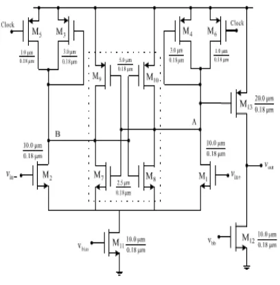
D. Logic Restorer
Fig. 5. Differential Schmitt trigger
A key piece of the Schmitt trigger is the hysteresis created through the regenerative info circuit, expressly a cross-coupled inverter pair. Exactly when another data banner is associated with the justification restorer, the clock is deserted low to high and turns OFFM5 and M6. It reduces the current gave to the differential speaker, which results in an increasingly small opening between the high and the low edge voltages. The cross-coupled inverter pair settles to a high or low state, and in this manner the yield of the strategy for thinking restorer. By then, the check banner ends up being low, andM5 and M6 are turned ON. The opening between as far as possible voltages ends up increasingly broad, which constructs the safety to clatter and aggravations.
E. Scalability plus Location of the PLC Receiver
The stage shifter is an as a substitute explicit square in addition to exact for our PLC beneficiary. The degree shifter has transistors in cascode, so it tends to be scaled to diminish convey voltages easily. consider that the resistive load for the banner extractor is displaced by techniques for a present day source. By then, both the sign extractor and the Schmitt cause have 3 transistors in cascode, which are normal for straightforward circuits. Thusly, they may scale identified with other basic circuits. It must be seen that the two squares are normally used creating squares for straightforward circuits, and were moved to the pervasive getting ready developments with reducing supply voltages. Right when as differentiated and virtual circuits, straightforward circuits do now not scale agreeably in the pass on voltage. Along these lines, the proposed PLC beneficiary, or its adjustments, likely won't be huge for marvelously low supply voltages containing the ones for low-control virtual circuits running at particularly low pass on voltages. The genuine zone of a PLC recipient at the chip impacts its execution. Unmistakably, a PLC authority discovered closer to the supply, i.e., the power stick by methods for which the information banner is associated, performs better. The expense is perhaps an all-inclusive sign heading from the collector to the objective rationale square to which the records are done. Effect at the sign lovely at different spots inside a chip transformed into examined, and
reproduction ramifications for a ball matrix exhibit bundle are mentioned.
4. RESULTS Schematic
Layout Design
Timing Diagram
A beneficiary for PLC at the IC level, which might be suitable to little information rate connections, similar to check style, framework investigating, in addition to blame diagnosing, was analyzed amid this paper. The anticipated PLC framework acknowledges a Binary raise adjustment topic, in addition to in this way the PLC recipient contains of 3 building squares. The degree shifter changes the dc dimension of the data flag to a 1/2 the arrangement voltage. The flag extractor bolstered differential electronic gear, takes out the dc voltage from the data motion with the assistance of a low-pass channel that diminishes contribute voltage vacillations in addition to hangs. The rationale renovators, in view of an error Schmitt trigger, take out rationale esteems from the data flag though raising the blast obstruction of the recipient. The PLC collector was considered to represent the practicability of a strong recipient as a flag of origination in addition to anecdotal in CMOS zero.18-μm hardware. The measurements clarify that the PLC recipient will endure a supply plunge of zero.423 V or twenty three.5%. the capacity scattering for the beneficiary is three.2 mW under one.8 V contribute. It needs an expansive extent of investigation endeavors to utilize the likely of the PLC in ICs totally. To mean a few, Demonstrating of power pins, ventures, and PDNs, channel depiction, balance notwithstanding different increase induction to plans, SNR versus bit-botch costs of a given contraption, structure of PLC gatherers and transmitters, and hurting impact of the information markers superimposed on essentialness lines to the action of automated circuits.
REFERENCES
1. W. C. Chung and D. S. Ha, “A new approach for massive parallel scan design,” inProc. IEEE Int. Test Conf., Nov. 2005, pp. 1–10. 2. L. T. Wang, C. E. Stroud, and N. A. Touba, System-on-Chip Test
Architectures: Nanometer Design for
Testability.SanMateo,CA,USA: Morgan Kaufmann, 2010. 3. S. M. Saeed and O. Sinanoglu, “Design for testability support for
launch and capture power reduction in launch-off-shift and launch-off-capture testing,” IEEE Trans. Very Large Scale Integr. (VLSI) Syst., vol. 22, no. 3, pp. 516–521, Mar. 2014.
4. H. Kim, Y. Lee, and S. Kang, “A novel massively parallel testing method using multi-root for high reliability,”IEEE Trans. Rel., vol. 64, no. 1, pp. 486–496, Mar. 2015.
5. J. G. Proakis, Digital Communications, 4th ed. New York, NY, USA: McGraw-Hill, 2000.
6. J. H. Reed, An Introduction to Ultra Wideband Communication Systems. Englewood Cliffs, NJ, USA: Prentice-Hall, 2005. 7. W. C. Chung, “The dual use of power distribution networks for data
communications in high speed integrated circuits,” Ph.D. dissertation, Dept. Elect. Comput. Eng., Virginia Tech, Blacksburg, VA, USA, 2006.
8. R. Thirugnanam, “Power line communications over power distribution networks of microprocessors—Feasibility study, channel modeling, and a circuit design approach,” Ph.D. dissertation, Dept. Elect. Comput. Eng., Virginia Tech, Blacksburg, VA, USA, 2008.
9. P. E. Allen and D. R. Holberg, CMOS Analog Circuit Design, 3rd ed. London, U.K.: Oxford Univ. Press, 2002.