International Journal of Innovative Technology and Exploring Engineering (IJITEE) ISSN: 2278-3075, Volume-8, Issue- 9S2, July 2019
Abstract—In traditional network the coupling of data plane and control plane makes the data forwarding, processing and managing of the network hard and complex. Here each switch takes its own decision, makes the network logically decentralized. To overcome the limitations in traditional network the Engineers developed a new model network known as Software Defined Network (SDN). This network the control plane is decoupled from the data plane making it less complex. It moreover has a logically centralized approach unlike the existing network. This separation enables the network control to be directly programmable and the architecture to be abstracted for applications and network services. SDN platform provides advantages like programmability, task virtualization and easy management of the network. However, it faces new challenges towards scalability and performances. It is a must to understand and analyze the performances of SDN for implementation and deployment in live network environments. SDN working with POX is studied. This paper analyses the working of POX controller and evaluates the performance metrics of POX controller for SDN environment. The emulation is done using the Emulation software.
Keywords: Traditional Network; SDN; Mininet; Emulator; Firewall; OpenFlow Protocol
I. INTRODUCTION
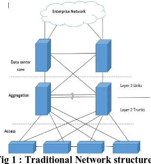
Today due to increasing network traffic and the users are rising exponentially. The network providers find it difficult to cope with it this phase of explosive expansion. The Traditional Architecture Network (TAN) has only two planes the application plane and the control plane as in Figure 1. The TAN is defined by the physical topology consisting of switches, routers and servers all cabled together. This indicates that once they are set, it is difficult to make changes in them. It is expensive and complex. This existing network model is not compatible for varying workload demand that is mostly the case in Datacenter’s and Cloud Environment.The traditional network has logical distributed control and device specific management. This network has low dynamic configurability because it has device specific management. In this network, the routing table is built up by the control plane based on the learning and awareness. The protocol support for each device varies
Revised Manuscript Received on July 18, 2019.
N. Saritakumar, Assistant Professor Department of Electronics and Communication Engineering PSG College of Technology Coimbatore, India.(E-mail:[email protected])
Adarsh V Srinivasan, Bachelor of Engineering Department of Electronics and Communication Engineering PSG College of Technology Coimbatore, India. (E-mail:[email protected])
Elfreda Albert, M.E Communication Systems Department of Electronics and Communication Engineering PSG College of Technology
Coimbatore, India (E-mail:[email protected])
Dr. S. Subha Rani Head of Department Department of Electronics and Communication Engineering PSG College of Technology Coimbatore, India.
with depending upon each of the vendor’s each release. Thus, making the traditional network less compatible to multi-vendor devices.
Troubleshooting in Traditional networks is difficult as the cause and the area of the error in specific is hard to be determined in the old network. All network devices have a control plane that provides information which is used to build a forwarding table. They consist of a data plane that consults the forwarding table. The forwarding table is used by the network device in decision making process, where to send the frames or packets entering the device. Both of the planes co-exist directly in a networking device. As the network expands in TAN increases the devices used, cost, complexity and time for the network too increases. Mostly the functionality of an appliance is implemented in dedicated hardware i.e. an Application Specific Integrated Circuit (ASIC) is often used for this purpose. Also, when a single device is needed to be added or removed in the traditional network, the network administrator will have to manually configure multiple devices like switches, routers, firewalls etc. on a device-by-device basis.
One of the major issue with the traditional networks that it is more prone to attacks from various sources, as the control and data are in the same plane. So enhanced security given is such that the intruders access to the controller to be blocked or terminated. Also, the authentications given to the packets are heavy and not always compatible for all kinds or types of devices working in a multi-user environment.
Fig 1 : Traditional Network structure
The CAP (Consistency, Availability and Partition Tolerance) theorem is a major issue faced in traditional network. So, moving on to Software Defined Network
Performance Evaluation of Pox Controller
for Software Defined Networks
[image:1.595.351.505.525.692.2](SDN) where the control plane is decoupled from the data plane and also, it permits dynamic configuration in the network [1]. Hence, it is much preferred.
II. BACKGROUND
SDN
As mentioned in Fig 2, the Software Defined Network (SDN) has three main planes.
They are:
a. Application plane b. Control Plane c. Data plane
This network is flexible and agile. This makes it user-friendly for the users to design, build and manage the network based on the needs. The deployment time taken by the Software Defined Network (SDN) is minimal. Also, the controllers can be easily programmed based on needs of the network. The Software Defined Network (SDN) has a logically centralized control plane which is programmable. The SDN has three types of controllers. They are:
a. SDN controller,
b. Southbound API’s (Application Programming Interface),
c. Northbound API’s
The SDN controller acts as the brain of the network in coordinating the flows within inter-domain and intra-domain networks. The Southbound API’s (Application Program Interface) relays on information to the switches and routers in the network. They form the connecting bridge between control and forwarding elements. The Northbound API’s regulate the communications with the applications and the deployed services. They are crucial to promote application portability and interoperability among different control platforms. There are many controllers currently used in Software Defined Network. They are POX, NOX, ONOS(Open Networking Operating System), Floodlight, Trema and Ryu [7].
Fig 2 : Software Defined Network structure
The application plane is the layer that allows the applications to interact and manipulate the behavior of network devices though the control plane. Mostly the network information is provided to an application via the Northbound API of the controller. The SDN applications are traffic engineering, mobility and wireless, measurement and monitoring, security and dependability and data center networking [8].
The data plane consists of the switches, routers, and all the data forwarding devices. The forwarding devices contain the flow tables. They are reconfigured and reprogrammed based on the needs of the network. The data traffic is much reduced due the systematic check in the data packet headers. They are analyzed by an application so-called the Virtual Network Function (VNF) analyzer. The packets headers are analyzed and then are routed to their destination based on the “Best Path to be Travelled”. Most of the OpenFlow switches used in SDN supports OpenFlow (OF) protocol [5]. The major security threats in SDN are Unauthorized Access, Data Leakage, Data Modification, Malicious /Compromised Applications, Denial of Service and Configuration Issues [6]. Also, by abstracting the network from the hardware, policies no longer are to be executed in the hardware, instead, they use of a centralized software application functioning as the control plane makes network virtualization possible in SDN.
OpenFlow Protocol
OpenFlow protocol is one amongst the initially used protocol in Software Defined Networking standards [3]. The recently used version is 1.3.0. The OpenFlow network policies and its applications are implemented as the OF applications, such that any application that works in SDN should support OF protocol. The application plane interacts with the northbound API via the control plane.
The OF controller interacts with the data plane is via the Southbound API. The controllers are distinct from the switches. This separation of the control from the forwarding allows for more sophisticated traffic management than is feasible for users by the Access Control Lists (ACLs) and routing protocols. Also, OpenFlow allows switches from different vendors mostly of each one with their own proprietary interfaces and scripting languages to be manage remotely using a single, open protocol. To work in an OF environment, any device needs should be communicated to the SDN Controller which mostly supports the OpenFlow protocol. Through this interface, the SDN Controller pushes down any changes to the switch/router related to the flow-table allowing network administrators with partitioning of traffic, controlling the flows for optimal performance, and start testing new configurations and applications.
The OF protocol is mainly supported by OF switches in the data plane. It runs over the “Secure Socket Layer” (SSL) in switches. The OpenFlow protocols defines three types of tables in the logical switch architecture as in figure 3. They are:
Flow tables
Group tables
Meter tables
International Journal of Innovative Technology and Exploring Engineering (IJITEE) ISSN: 2278-3075, Volume-8, Issue- 9S2, July 2019
is also a possibility for the creation of multiple flow tables in a pipeline fashion. It also directs the flow to the Group tables which triggers the various actions in the flow. The Meter table can also trigger actions which leads to performance variations in the flows.
Mininet
[image:3.595.316.537.203.347.2]It’s a network emulator [2] [4]. In this software, the creation of Virtual hosts, switches, controllers and links are possible. It runs in standard LINUX platform. The switches used here support OpenFlow protocol which is highly flexible for custom routings and Software Defined Network. Mininet is actively developed, supported and is released under a permissive BSD Open Source license. It’s simple, open-sourced and less expensive, so mostly preferred for developing OpenFlow applications. It also, permits multiple developers to access the same topology. It has its own Command Line Interface (CLI) for debugging and running network wide tests.
Fig 3 : Open Flow working structure
It supports arbitrary custom topologies and basic parametric topologies. Also provides a straight-forward approach and extensible Python API for the network creation and experimentation. The MiniNet network runs the real code in the network application, Linux kernel and the network stack.
POX Controller
POX is the upgraded Python based version of NOX controller. It is an open source controller. It has a high level for query-able topology and support for virtualization. It was initially used as an OpenFlow(OF) controller but now it is used as a switch too. It provides reusable components, path selection, topology discovery, load balancing etc. It is the default controller used when a controller is evoked in Mininet software. It supports Graphic User Interface (GUI) and visualization tools.
It architecture is simple compared to other controllers as in figure 4. The communication between the controller and the switches is using OF protocol. The OF switches behave just like forwarding devices. They perform only on the instruction from the controller. When the switch is ON, at the next instant it will immediately connect with the controller. Each switch has its own flow table. Initially they are empty.
At the arrival of a packet, the switch sends a Packet-in message to the controller. Then the controller inserts flow
entire in the flow table of the switch regarding how to handle the packet. The flow entry has 3 parts: rule, action and counters. So as each packet passes a flow entry is installed in the switch such that it may be able to handle the packet without the intervention of the controller. If the flow entries do not match with the one in the controller, it sends a response the discard the packet.
The benefits of using POX is the it need less memory space to operate unlike other controllers but has low throughput performance when compared with other controllers.
Fig 4 : POX Controller architecture
D-ITG
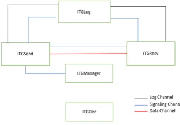
[image:3.595.84.249.299.434.2]D-ITG (Distributed Internet Traffic Generator) is a platform that can generate traffic which adheres to the patterns where the inter departure time of the packets and the packet size can be defined [6]. It supports a lots of probability distribution like Pareto, Cauchy, Poisson, Normal and Gamma. It also supports wide number of protocols like: TCP, UDP, ICMP, Telnet and VoIP. The users can obtain the details of the flow of packet like the One-Way-Delay(OWD), Round-Trip-Time (RTT), packet loss, Jitter and the throughput measurement. It also permits the users to set the Type of Service(TOS) and the Time to Live(TTL) of the packet
Fig 5 : D-ITG Software Architecture
[image:3.595.332.514.554.680.2]of D-ITG. As it is in the architecture a separate signaling channel between the sender and receiver for communication and it is ruled by a special protocol Traffic Specification Protocol(TSP). D-ITG mainly comprises of ITGSend, ITGRecv and ITGLog. The ITGSend is the only source of traffic generation. It can operate in various modes like single flow mode, multiple flow mode and daemon mode. In single flow mode just generates a one flow.
A single thread is responsible for this flow generation and management. In multiple flow mode sets of flows are generated. It has many threads to manage flow. One among them implements the TSP while the other generates traffic flows. To collect the statistics of the flow, connect to the log host for it. ITGRecv works by listening to the TSP connections. When a connection requesting thread arrives, it generates a thread that is responsible for its communication with the sender. Each flow is received as a separate thread. ITGLog indicates a log server running on a different host than the sender and the receiver. It is capable to receiving and storing multiple information from multiple sender’s and receivers. Mostly the log information is usually sent using reliable TCP channel or rarely in unreliable UDP channel.
III. NETWORK TOPOLOGY
Fig 6 : The Topology of the Simulated Network
A linear topology was implemented with 10 switches and 11 hosts and all the further analysis and simulations were done using the above-mentioned topology.
IV. IMPLEMENTATION & RESULTS
This work mainly focusses on the performance of POX controller using Mininet software. As POX is the default controller used when a controller is evoked in for any purpose in Mininet. All the switches used here operate with OF protocol. This protocol helps it easily and effectively communicate with the controller regarding the flow. Performance evaluation of POX controller is checked. Certain parameters are deemed for testing purpose [5].
They are:
1. Bandwidth Utilized 2. CPU load allocation 3. Packet Loss 4. Scalability
The topology used is mostly linear topology with the size of hosts or switches increasing exponentially i.e. 5,10,15.…80. or a tree topology with depth=1 and fanout=2. For test purpose the fanout is increased from 2 to 80 i.e. the number of hosts connected to the switch connected to the controller is increased exponentially.
Bandwidth Utilized
For performance analysis the bandwidth usage is also an important factor. To test the Bandwidth utilization, initially a linear topology with 80 hosts and switches can be seen in figure 6 is used. Then a bandwidth of 10Mbps is allocated
and the utilized bandwidth by the switches using iPerf is recorded. Then gradually the allocated bandwidth is increased by ten to 20Mbps and then at an exponential phase till 50 Mbps.
[image:4.595.305.550.141.327.2]The simulation is run and the test results are tabulated in the Table 1 for reference.
Table 1 : Bandwidth utilized by the Network
Switch Count
Utilized BW (For allocated 10 Mbs)
Utilized BW (For allocated 20 Mbs)
Utilized BW (For allocated 30 Mbs)
Utilized BW (For allocated 40 Mbs)
Utilized BW (For allocated 50 Mbs)
1 9.388 19 27.8 35.6 40.3
10 9.366 18.3 27.9 24.3 45.6
20 9.285 18.5 27 17.3 44.6
30 9.26 18.3 26.8 31.3 37.7
40 8.946 18.1 24.5 32.4 37.4
50 8.84 17.2 22.1 28.2 40.3
60 8.796 14 24.9 27.3 38.6
70 8.28 16.9 24 24.9 36.3
80 8.11 14.5 23.1 22.6 35.1
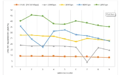
[image:4.595.323.529.469.599.2]Then the values in Table 1 is plotted as a graph as in figure 7. From the figure it can be analyzed that for 10Mbps the bandwidth utilized is minimum and constant. For 20Mbps the effective utilization is till 50 switches and for 30Mbps it is till 45 switches. At 40Mbps unlike others effective utilization of bandwidth is at 40 to 50 switches and at 50Mbps effective bandwidth utilization is at 10 to 20 switches. This brings to the conclusion that effective bandwidth utilization happens at 20 to 50 switches. After that wastage of bandwidth is detected.
Fig 7 : Plot of Bandwidth Utilization Vs Switch count
CPU Load Allocation
This checks the efficiency of how the POX controller works depending on the amount of load given. So, for this test a Tree topology is considered as in figure 6 with depth = 1 and fanout = 2. Initially 10% of the CPU is allocated and 10*10^9 bits is sent from the controller to the Hosts. The number of bits received per second value is taken. Gradually the CPU load is increased by10 to 20%.
International Journal of Innovative Technology and Exploring Engineering (IJITEE) ISSN: 2278-3075, Volume-8, Issue- 9S2, July 2019
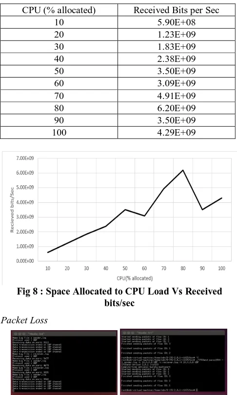
[image:5.595.46.289.105.510.2]allotment better performance is achieved i.e. when maximum CPU space is allocated to CFS (Completely Fair Scheduler), maximum packets are received.
Table 2 : Packets received based on the CPU Load
CPU (% allocated) Received Bits per Sec
10 5.90E+08
20 1.23E+09
30 1.83E+09
40 2.38E+09
50 3.50E+09
60 3.09E+09
70 4.91E+09
80 6.20E+09
90 3.50E+09
100 4.29E+09
Fig 8 : Space Allocated to CPU Load Vs Received bits/sec
[image:5.595.45.290.105.399.2]Packet Loss
Fig 9 : D-ITG used in Linear topology
The final test is to check the Packet loss. It is an important factor when it comes efficiency of packet delivered. It also determines the networks reliability. For this a traffic generator known as D-ITG (Distributed Internet Traffic
Generator) is used. For this test a linear topology is taken into consideration with 10 hosts and switches. Here hosts h6 and h8 are the senders. Host h1 is considered as the receiver and h10 is made remote log host as in Fig 9. flows with varying the packet size from 64 to 1450 bytes are sent.
Table 3 : Packet loss based on Packet size
From the Fig 10, at 200 and 900 bytes there is a sharp rise in the packets lost. At about 450 to 800 the packet loss is stable. After 1200 the loss is rising exponentially. Initially there is no packet loss, but from 192 there is a small loss which gradually increases
Fig 10 : Plot of Packet Size Vs Packet Loss
V. ADVANTAGES
There are certain advantages of using a Software Defined Network (SDN). The programmability of a Network is very essential to any organization where the operational costs are reduced by many folds. The existing conventional network can be expanded which in turn increases the scalability and provides the users with a lot of re-usability options.
The SDN provides a Centralized view of the entire network, making it easier to centralize enterprise management and provisioning. The SDN also provides centralized security as it can be controlled virtually.
The ability to shape and control data traffic is another advantage of using a SDN. Being able to achieve this, the Quality of Service (QoS) is increased and this system also provides flawless user experience. So content delivery is Guaranteed.
VI. CONCLUSION
[image:5.595.328.520.332.481.2]switches in the network. When 75-80% of the CPU load is given to Completely Fair Scheduler, it performs better. The packet loss drastically increases after 1200 bytes, which makes this controller less reliable after. Mainly the SDN is a boon for data centers where large amount of data, user’s and devices are handled. So, reliability, scalability, are some important parameters needed for SDN to be deployed. The latest hardware for Software Defined Network, the OpenFlow switch Zodiac FX can be deployed with POX controller.
REFERENCES
1. Diego Kreutz, Fernando M. V. Ramos, Paulo Verissimo,
Christian Esteve Rothenberg, Siamak Azodolmolky, and Steve Uhlig, “ Software Defined Networking : A Comprehensive Survey,” 2014, in Proceedings of the second workshop on Hot topics in software defined networks
2. Faris Keti, Shavan Askar,” Emulation of Software Defined
Networks Using MiniNet in Different Simulation
Environments”, 2015, 6th
International Conference on intelligent Systems, Modelling and Simulation, pp 9-2,2016
3. Fei Hu, Qii Hao and Ke Bao, “A Survey on Software Defined
Network and OpenFlow: From Concept to Implementation” in IEEE Communication surveys & Tutorials,vol.16,No.4,Fourth Quarter 2014
4. Rogerio Leao Santos de Oliveria, Christiane Maire
Schweitzer, Ailton Akira Shinoda, Ligia Rodrigues Prete,” Using mininet emulation and prototyping Software Defined networks”, 2014, IEEE Colombian Conference on Communication and Computing(COLCOM), pp 4-6,2014
5. The Openflow Switch, openflowswitch.org.
6. S.Avallone, S.Guadagno, D.Emma and A.Pescape,“ D-ITG
Distributed Internet Traffic Generator,” 2014, Proceedings of the First international conference on Quantitative Evaluation of Systems (QEST’04).
7. Saleh Asadollahi, Bhargavi Goswami and Mohammed
Sameer,” Ryu Controller’s Scalability Experiment on
Software Defined Networks”, 2016, 7th
International Conference on intelligent Systems, Modelling and Simulation, pp 9-2,2017
8. Semaliansky R.L, “SDN for Network Security”, 2014 IEEE