Abstract: This paper deals about one of the FACTS devices which is called UPFC (Unified Power Flow Controller). It is used to control reactive (KVAR) and active power (KW) by means of adjusting bus voltage at the located line. UPFC can improve the quality of power within their limits on the targeted line. That’s why this device has the different way of controlling the power flow and voltage stability. Without UPFC, it is impossible to control voltage, reactive and active power. In this thesis, we can also analyze by attaching fuzzy logic controller to this system. The simulation models are made in MATLAB software. Under simulation we get results for with and without using UPFC and then we compare these results in the form of active and reactive power in the required line. By comparing these results, we decide that UPFC is an ideal controller.
Index Terms: fuzzy logic, matlab, upfc, voltage stability
I. INTRODUCTION
In a power grid system the electrical power is used to produce and transmit the power. This is classified by generation, transmission and distribution system. These sub-divisions at regulated rates power is produced in a specific region under one system. So to commercialize power deregulation is necessary. In that case distribution, transmission and generation occur individually. Power units are relayed to pressure at functioning generating unit and loading of working x-ion line at their heat limits. For the power system to operate effectively, without any variations in system security and quality maintenance in power supply. At higher frequency situation, the x-line loss and generating unit loss happens. Fuzzy logic is used to resolve the issues in power quality in the transmission network. For the development of UPFC on controlling the power flow through simulation, there has been lack in recognizing the experiments done on various UPFC controllers and its execution in real time operation. Among all the FACTS devices, Unified Power Flow Controller (UPFC) has major functional abilities that are regulation of voltage, phase angle correction, series compensation and controlling of real and reactive power. However, these conventional converters which focus on steady state analysis functions only under planning stage of the power system network and it is inapplicable for dynamic operation analysis.
Revised Manuscript Received on October 05, 2019.
K. Fedora Priyanka, M.Tech Student EEE, Gokaraju Rangaraju Institute of Engineering and Technology (JNTUH), Hyderabad, India.
Mrs.V.V.S. Madhuri, Associate Professor, Gokaraju Rangaraju Institute of Engineering and Technology (JNTUH), Hyderabad, India
Dynamic operation analysis is nothing but practical operation of power system. In this operation the power flow gets fluctuated frequently due to change of the load and disturbances.
The performance of conventional UPFC controllers at different operating conditions is not adequate. That is the major drawback. This is because of the control parameters obtained at particular operating system conditions. To overcome these limitations in the conventional UPFC controllers, the fuzzy logic based UPFC is implemented to improve the power quality and to control the power flow properly at certain operating conditions in the power system network. The fuzzy logic controller solves the complex system problems. This fuzzy logic controller is strong, powerful and it can provide control of dynamic power flow at certain particular load conditions. In this paper 5 bus system is taken to affirm the performance of the UPFC with fuzzy logic based controller, whether it has the ability to improve the power quality of the transmission network.
II. STRUCTURAL DIAGRAM OF UPFC
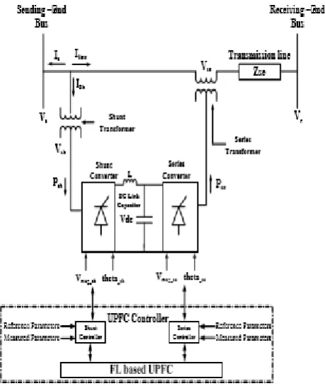
Among all the other devices, UPFC is the multipurpose device. Figure 1 shows the basic structural diagram of UPFC. UPFC is mainly consists of STATCOM (static compensator) and SSSC (static synchronous series compensator). These are voltage source converters. Series connected VSC is known as SSSC and shunt connected VSC is known as STATCOM. A DC link capacitor is used for coupling of converters. Two isolation transformers are used to isolate the converter from transmission line. These transformers provide isolation to the system. Due to switching harmonics are produced. To reduce these harmonics Low pass AC filters are designed. STATCOM and SSSC converters use insulated gate bipolar transistors (IGBTs) for switching purpose.
Implementation of UPFC for Improving the
Power Flow and Voltage Stability with Fuzzy
Logic Controller
Figure 1: Model diagram of UPFC
III. UNIFIED POWER FLOW CONTROLLER
In this implementation of UPFC, two VSCs are arranged. These two VSCs namely STATCOM and SSSC are connected by dc storage capacitor which is operated by common dc link. By this connection of system, it functions as an ideal ac-to-ac power converter, it provides active power in both the directions between output terminals of two converters and these VSCs individually generates or absorbs reactive power at the output terminal.
Converter 2 mainly functions in the UPFC by injecting voltage Vpq with the magnitude Vpq and phase angle ρ in series with line through a transformer. The voltage which is injected in the system acts as synchronous ac voltage source. The current which flows in the transmission line through the voltage source results in real and reactive power. The reactive power which is exchanged is generated internally by the converter and the real power which is exchanged at ac terminal is generated as positive or negative power demand at the dc link.
[image:2.595.316.523.49.342.2]In this the main function of these two converters is that the converter 1 generates or absorbs the real power demand by converter 2 at a dc link. The converter 2 generated dc link power demand is converted to ac by converter 1 and it is coupled to transmission line bus through a shunt converter transformer. If converter 2 needs real power, then converter 1 generates or absorbs reactive power and provides shunt reactive compensation of the line. Here the point to be noted is if the direct path for real power is closed by the series voltage injection with STATCOM and SSSC, similarly the exchanged reactive power is also supplied or absorbed by converter 2 and is not through the transmitted line. Thus STATCOM is operated at UPF or can be controlled to generate exchanged reactive power with individual line of exchanged reactive power by SSSC. So through this no reactive power can be flown through the UPFC dc link.
[image:2.595.54.284.59.332.2]Figure 2: Two- machine power system
Figure 3: Phasor diagram
IV. MODELLING OF UPFC IN SIMULINK
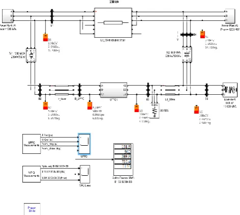
[image:2.595.303.549.565.707.2]UPFC is to control power flow in a 500KV/230kV transmission system. In this construction, it is associated with five buses (B1,B2,B3,B4,B5) connected by three transmission lines (L1,L2,L3) and two units of 500kV/230kV transformers named as T1 and T2. In 230kV system two power plants are placed which produce 1500MW to a 500kV, 1500MVA and a 500MW load attached at bus B3. In every power plant a speed regulator, an excitation system and a power system stabilizer (PSS) are attached. Usually in this process 1200MW power from power plant 02 transferred to 500kV of two identical transformers with 400MVA attached to buses B4 and B5. In this design of UPFC only two transformers are available out of three. As per the load flow the power generated by power plant 02, the transformer banks receive 800 MVA and 96 MW is flowing in loop. With this power flow transformer T2 is loaded to 99MVA.
Figure 4: Simulink model without UPFC
the real and reactive power at bus B3 of 500kV, and voltage at bus B_UPFC. In a UPFC two 100MVA, IGBT type, converters i.e., series and shunt converters. The series converter produce maximum 0.1 p.u of rated phase voltage in series attached with line L2.
Figure 5: Simulink model with UPFC
V. PROPOSED FUZZY LOGIC CONTROLLER
BASED UPFC
In this research for the improvement of power quality we use fuzzy logic based UPFC in transmission line. Shunt and series converters are developed for the fuzzy logic based UPFC. The controlling strategy of the converters is explained in this paper.
A. Fuzzy logic toolbox
By using fuzzy logic toolbox software we can create and edit fuzzy interference system. This fuzzy interference system can be created using graphical tools or command line functions, or by using clustering neuron fuzzy techniques it can be generated automatically. This fuzzy logic toolbox allows to run C program directly. This can be done by Fuzzy Interference Engine which reads the fuzzy systems from a Matlab session. The toolbox represents complex system nature, by using simple logic rules and these are being implemented in fuzzy interference system.
[image:3.595.51.292.127.316.2]Fuzzy interference is a method that explains about the values in the input vector, based on user defined rules it assigns values to the output vector.
Figure 5: Fuzzy interference system
Figure 6: Simulik model with fuzzy logic controller
The rule table for the fuzzy logic controller is as given below.
The fuzzy rules are applied on the basis of IF-THEN rules. These are mainly used to assign the outputs for the input signals. Here all the 49 rules are used for fuzzy logic controller because of having number of inputs 2 and number of variables are 7 for each. For active and reactive power (Vac), (Vdc) these rules are implemented.
The process of converting fuzzy linguistic variables to real crisp values is known as Defuzzification. One of the methods in defuzzification is Weighted average defuzzification method (Sugeno-type). It is mentioned below.
W is the real crisp value
[image:3.595.57.292.664.742.2]Figure 6: Membership functions
VI. EXPERIMENTAL RESULTS
Table 1 shows the magnitude of voltage at buses of power system. At buses 1,2,3,4,5 of power system , amplitude of voltage is shown.
Table 1: Amplitude of Voltage
Table 2 shows the active power flow in the transmission line system. At buses B1,B2,B3,B4,B5 the real power flow is illustrated.
Table 2: Active Power
Table 3 shows the reactive power flow in the transmission line
system. At buses B1,B2,B3,B4,B5 the reactive power flow is illustrated.
Table 3: Reactive Power
With Fuzzy logic controller, the active power flow in transmission line system can be varied.
Table 4: Active Power
VII. SIMULATION RESULTS
The results of power flow like reactive power, active power and voltage in the transmission lines of the electrical power system are illustrated. By the implementation of UPFC on buses of power grid system, the impact and output results of magnitude voltage, voltage phase angle and active and reactive power flow in transmission lines are analyzed.
Figure 7: Simulation results of VPQ waveforms without UPFC
Figure 8: Simulation results of VPQ waveforms with UPFC
UPFC for voltage, reactive and active power flow in the system.
Figure 9: Simulation results of VPQ with fuzzy
Figure 10: Simulation results of VPQ with fuzzy
VIII. CONCLUSION
In this paper with results of Unified Power Flow Controller (UPFC), we conclude the power flow in the transmission line. In the transmission of grid system, the voltage magnitude, phase angle and line parameters are maintained very easily. So, managing the power from one to another place, the process of adjusting the power flow and adding external voltage is applicable. UPFC is extremely valuable because the way of analyzing the electrical system and reading the results shows how a UPFC is important in an electrical grid system. In this active and reactive power are examined on electrical transmission lines. This research paper deals with the simulation of 5-bus system to improve the quality of power transfer stability and system stability of the line by introducing UPFC at the supply side by using current simulation method. Without UPFC, the improvement of power transfer capability and system stability cannot be performed. The results of with and without UPFC are examined by means of reactive and active power flows in the transmission line. The results of with UPFC got better results compared to without UPFC. The simulation of UPFC in an electrical power grid system is also done with the attachment of fuzzy logic. In fuzzy logic system the active power and reactive power are generated with respective of the given inputs. The fuzzy logic is used to develop series and shunt controllers of UPFC. The performance of fuzzy logic based UPFC has been tested for voltage, reactive and active power flow in the lines of power system. Compared to the grid system with UPFC the active power is generated less with the fuzzy interference system. With the fuzzy logic we can easily map the inputand output power. Thus the power generated in this electrical power grid system is illustrated.
REFERENCES
1. Mausam yadav, Ankur soni “Improvement of power flow and voltage
stability using unified power flow controller” IEEE paper publications
2. Hingorani, N.G, Gyugyi L.,A text book on “Understanding FACTS
Devices”,
3. Sedaghati Reza, Borazjani Omid, Dehghani Pilehvarani Alireza., A
textbook on “Power System Transient Stability Improvement by Facts Device”
4. K. Gaurav and N. Saxena, "Power Quality improvement using UPFC,"
International Journal of Electrical, Electronics and Computer
Engineering, Vol.2, No.2, pp. 30-33, Jan 2013
.
5. S. Vaibhav Kale, R. P.Prashant and R. Khatri, "Unified Power Flow
Controller for Power Quality Improvement," International Journal of Emerging Science and Engineering (IJESE), Vol.1, No. 10, pp. 1-4, Aug. 2013.
6. D. Mohanty, A, Ahamad, and M. A Khan, "Modeling, Simulation and
Performance Analysis of FACTS Controller in Transmission line," International Journal of Emerging Technology and Advanced Engineering, Vol. 3, No. 5, pp. 429-435, May. 2013.
AUTHORS PROFILE
K. Fedora Priyanka M.Tech Student in Power Systems, EEE, Gokaraju Rangaraju Institute of Engineering and Technology (JNTUH), Hyderabad, Telangana, India.