3D experimental study on a cylindrical
fl
oating breakwater system
Chun-Yan Ji
a, Yu-Chan GUO
a, Jie Cui
a, Zhi-Ming Yuan
a,b,n, Xiao-Jian Ma
a aSchool of Naval Architecture and Ocean Engineering, Jiangsu University of Science and Technology, Zhenjiang 212003, China b
Department of Naval Architecture, Ocean and Marine Engineering, University of Strathclyde, Glasgow, UK
a r t i c l e i n f o
Article history: Received 1 January 2016 Received in revised form 8 July 2016
Accepted 22 July 2016 Available online 10 August 2016
Keywords:
Floating breakwater system 3D experimental study Wave transmission coefficient Wave reflection coefficient Wave dissipation coefficient Motion responses
a b s t r a c t
The objective of the present study is to investigate the performance of a cylindricalfloating breakwater system based on 3D experimental tests. The experiments were carried out in the wave basin (36m*60m*1.5m)of the Ocean University of China. The cylindricalfloating breakwater system consists of 10cylindricalfloating breakwater units and 10mesh cages with balls in them, connected by 18 connectors and moored by a taut mooring system. The wave transmission coefficients, reflection coefficients, dis-sipation coefficients and motion responses of thefloating breakwater are measured in both oblique and beam sea conditions. It is found that with the increase of the wavelength, both of the wave transmission coefficients and motion response amplitude of the FB system suffers an increase before it reaches its peak value, followed by a decrease trend. It can be concluded from the experiments that the proposed FB system has a satisfactory performance and it can be used to a wide range of sea conditions.
&2016 The Authors. Published by Elsevier Ltd. This is an open access article under the CC BY license (http://creativecommons.org/licenses/by/4.0/).
1. Introduction
Thefloating breakwaters (FBs) have been extensively studied in the last few decades. These studies focus on different types of the floating breakwaters, such as cylindrical type (Ozeren et al., 2011), single pontoon type, double pontoon type, broad-net type (Dong et al., 2008), box type, Π shape (Gesraha, 2006) so on. Floating breakwaters attenuate waves mainly in two ways: (1) reflecting waves; (2) disturbing the motions of the wave particles. Compared to the traditional breakwater, the floating breakwater has many advantages: (1) Environment friendly: FB will not block the ocean flow and the ecosystem can be protected; (2) Economy: FB is more economical than traditional breakwater, especially in deep water; (3) Feasibility: FB has lower requirement of seabed condition and it is easy to be installed; (4) Thefloating body, mooring line and anchor are easy to be manufactured. In addition, the existence of specific environmental design parameters, such as poor founda-tion and deep water condifounda-tions, water circulafounda-tion and esthetic considerations, enhanced the utilization of floating breakwater (McCartney, 1985).
In order to investigate the efficiency of wave attenuation of different types offloating breakwaters, many experiments studies have been carried out.Arunachalam and Raman (1982)conducted
a two-dimensional model study to investigate the transmission coefficient of a horizontal floating plate breakwater. Bayram (2000)evaluated the performance of a slopingfloat breakwater by a two-dimensional model study.Stamos et al. (2003)conducted a 2D experimental study to compare the reflection and transmission characteristics of submerged hemi-cylindrical and rectangular ri-gid and water-filledflexible breakwater models.Ragih et al. (2006) carried out a 2D experiment to investigate the wave attenuate by using sphericalfloating bodies.Martinelli et al. (2008)carried out a 3D experiment to study the effect of different layouts offloating breakwaters on wave transmission, loads along moorings and connectors, under oblique waves.Dong et al. (2008)measured the wave transmission coefficients of three types of breakwaters un-der regular waves with or without currents by a two-dimensional physical model tests.Wang and Sun (2010)conducted a 2D ex-perimental study to investigate the hydrodynamic efficiency of a porousfloating breakwater.Ozeren et al. (2011)conducted a la-boratory investigation of the hydrodynamic interaction of cylind-rical breakwaters with monochromatic waves in deep and transi-tional water depths.Peña et al. (2011) investigated wave trans-mission coefficient, mooring lines and module connector forces with four different designs offloating breakwaters by 2D and 3D physical model tests. He et el. (2012) investigated the hydro-dynamic performance offloating breakwaters with and without pneumatic chambers in a waveflume.Koraim and Rageh (2013) studied the hydrodynamic efficiency (the wave transmission, re-flection, and energy dissipation coefficients) of afloating break-water system, which consists of a rectangular box and a series of Contents lists available atScienceDirect
journal homepage:www.elsevier.com/locate/oceaneng
Ocean Engineering
http://dx.doi.org/10.1016/j.oceaneng.2016.07.051
0029-8018/&2016 The Authors. Published by Elsevier Ltd. This is an open access article under the CC BY license (http://creativecommons.org/licenses/by/4.0/).
nCorresponding author. Dep. of Naval Architecture, Ocean & Marine Engineering,
University of Strathclyde. Henry Dyer Building, G4 0LZ, Glasgow, UK. Tel:þ44 (0)141 548 3308. Fax:þ44 (0)141 552 2879.
elastic performance of a free, flexible, mat-shaped floating breakwater that consists of a grid offlexible floating modules connected flexibly in both horizontal directions. The investiga-tion had been conducted in the frequency domain under the action of oblique incident waves.Peng et al. (2013) studied the interactions of waves with submerged floating breakwaters moored by inclined tension legs, using a numerical wave tank model which based on the Navier–Stokes solver.Koraim (2015) mathematically and experimentally investigated the hydro-dynamic characteristics of the semi immersed caissons break-water supported by two rows of piles.
FB's oscillating motion will generate the radiation waves. The waves propagate upstream can be regarded as a way to attenuate incoming wave energy. Therefore the motion response is another important factor of assessing afloating breakwater configuration. By using thefinite element method (FEM),Hanif (1983)analyzed hydrodynamic properties of an elliptical cylinder floating break-water in heaving and swaying motions.Sannasiraj et al. (1998) conducted a 2D experimental and theoretical investigation to study the motion responses and mooring forces of a pontoon-type FB for different mooring line configurations.Rahman et al. (2006) developed a numerical model by using the volume offluid (VOF) method as well as 2D experimental studies to estimate the non-linear dynamics of a pontoon type moored submerged breakwater under wave action for both the vertical and inclined mooring alignments.Najafi-Jilani, Rezaie-Mazyak. (2011)numerically ana-lyzed the movement pattern of a floating breakwater, using Smoothed Particle Hydrodynamic (SPH) method as a Lagrangian scheme.Sannasiraj et al. (1995), Abul-Azm and Gesraha (2000), Loukogeorgaki and Angelides (2005), Zheng et al. (2006) and Gesraha (2006) also had investigated the dynamic response of floating breakwaters under the action of incident oblique waves.
connectors, ten mesh cages and 12,000 balls, and it is moored by 64 mooring lines. This scaled system represents the real physical model which is to be used in engineering practice. For such a complicated floating breakwater system, no single experimental study yet has been conducted to explore its wave attenuation performance. Therefore, the experimental procedure, as well as thefindings acquired from the tests will be of benefit for the re-searchers to have a better understanding of the coupled behavior between multiplefloating bodies.
Ji et al. (2015)conducted a 2D experiment to study a new type of floating breakwater. Comparing the four models’ capacity of wave attenuation, Model 3 (the traditional cylindrical FB with a mesh cage and balls) is the best configuration. Based on Ji et al. (2015), the present paper conducted a 3D hydrodynamic experi-ment to investigate the hydrodynamic efficiency (wave transmis-sion coefficients, reflection coefficients, and energy dissipation coefficients) and motion responses (surge, sway, heave, roll, pitch and yaw motion) of afloating breakwater system within the action of both beam and oblique wave as a function of wave period and wave height separately.
2. Cylindricalfloating breakwater introduction
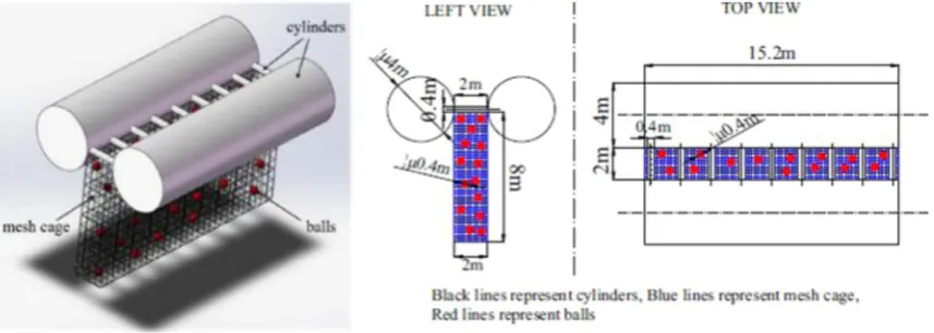
According toJi et al. (2015), the main structure of a traditional cylindrical FB includes eleven cylinders, which are made of reinforced concrete. Two of them have the size of 4 m (diameter)*15.2 m
[image:2.595.90.519.578.731.2](length), while the others are 0.4 m*2 m. Nighty eight percent of the wave energy is transmitted underneath the water surface, to disturb particle orbit and reduce the cost, a mesh cage with the length of 15.2 m and the width of 2 m was hanged blow the main structure. In order to enhance the dissipation of wave energy, 1200 rubber hollow
balls with the diameter of 0.4 m and the density similar to water are added into the cage (Fig. 1).
3. Experiment
3.1. Experimental facilities
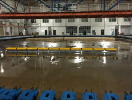
The model tests were conducted in the three-dimensional wave basin in the Hydraulics Modeling Laboratory of Ocean University of China (as shown inFig. 2). The wave basin is 60 m long, 36 m wide and 1.5 m deep. But in the present experiment, only the length of 45 m length can be used, while the rest length of 15 m is the sand beach. The wave basin is equipped with a 33.75 m hinged plate wave generator, which can make both the regular and irregular waves through a computer. In the present study, all the incident waves are regular wave and the test duration is 90 s. In the opposite end, there is a wave-absorbing beach, which is stabilized by an armor layer, to reduce wave reflection. The slope of the wave-absorbing beach is 1:5. In order to measure the free surface elevation of the wave ba-sin, 5 wave gauges (WGs) are used to measure the incident waves and transmitted waves and the location of them can be found in Fig. 3. The distance between WG1, WG2, WG3, WG4, WG5 and the x-axis is 10 m, 5.31 m, 5 m, 10 m and 10.31 m respectively. WG1is used to measure incident wave, WG2 and WG3 are used to sepa-rate the incident wave and the reflected wave from the measured two waves while WG4 and WG5 are used to separate the trans-mitted wave by means of the two measured waves. In order to measure the motion responses, a 6-DOF measure system was ap-plied, which includes a 6-DOF camera and three luminous. The distance between thex-axis and the 6-DOF camera is 4 m. Three luminous sources were installed in the middle of the cylindrical floating breakwater system, so that the camera can receive signals from these sources. The motion trail of the three luminous re-presents the actual motion offloating breakwater units.
3.2. Experimentalfloating breakwater
Considering the size of the wave basin and the wave frequency range that can be generated by wave generator controlled by a computer, the model is made based on geometrical similarity with scale factor of 1:40. In the present study, we make some adjustments in the dimensions for the traditional cylindrical FB with a mesh cage and balls, mentioned in Ji et al. (2015), to be the experimental models. The same cross section of the cylindrical FB proposed inJi et al. (2015)is used in this paper. Thefloating breakwater system (as shown inFig. 3) consists of 10 cylindricalfloating breakwaters units
connected by 18 elastic connectors and 36 chains (as shown inFig. 5), as well as 10 mesh cages with balls in them (Fig. 4).
The cylindrical FB has two 0.25 m (diameter)*1.5 m (length)
cylinders and thirteen 0.03 m (dimeter)*0.125 m (length) cylinders. In addition, it includes a 1.5 m long, 0.125 m wide and 0.5 m high mesh cage hanging below the main structure too. 1520 rubber balls with 3.4 cm diameter are pre-placed into every mesh cages to dissipate the wave energy.
The length of the connector is 0.125 m. These connectors are made from rubber whose density is 1300 kg/m³, and include three components: two small inter cylinders and one outer hollow cy-linder. Two inner cylinders are nailed into the units’cross-section and wrapped by the outer rubber cylinder. Those connectors are used mainly to absorb pitch moment and restrain the collision of two units. Due to the large stiffness of the rubber (similar material as tire), the relative motion on surge, sway, heave and roll between two adjacent units can be negligible. However, it allows the re-lative pitch and yaw motion, which can transfer wave energy to the elastic potential energy.
Between every two units, two chains are hinged to reinforce the connection. The total length of thefloating breakwater system is 16.125 m. The main parameters of the experimental module are listed inTable 1. In the present study, we choose 90°to represent beam sea condition and 67.5°to represent oblique waves.
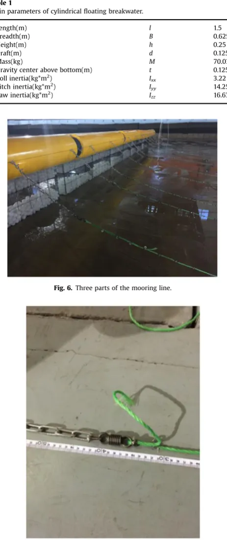
The structures were modeled according to geometrical and mass similarities (mass, gravity center, buoyancy and mass mo-ment of inertia). For the mooring lines, the geometrical and mass similarities arefirstly satisfied by adjusting the distribution of nuts (see Fig. 6). Elastic similarity can be achieved by adjusting the spring distribution (seeFig. 7).
By releasing the structure from several non equilibrated posi-tions, natural modes of oscillations in 3D have been assessed in the laboratory. The natural period of oscillations of the floating breakwater system are given inTable 2.
3.3. Mooring system
The taut mooring system is used for the floating breakwater system, and 64 mooring lines are symmetrically arranged along-side thefloating breakwaters, as shown inFig. 3. The angles be-tweenx-axis and the mooring lines in two terminal unites (No. 2, 63, 31, 34) are 60°, 60°,120°, 120°respectively. The length of each mooring line is 3.875 m. Each mooring line consists of three components: chain-rope-chain. The length of the chains in the lower and upper end of the mooring lines is 0.5m, while the length of the rope is 2.875 m, as shown in Fig. 6. Besides, the springs and nuts (as shown inFig. 7) are used to adjust the stiff-ness and weight of the mooring lines respectively. The main parameters of the mooring lines are listed inTable 3and the axial rigidity of the chains and ropes can be measured by experiments.
3.4. Experimental conditions
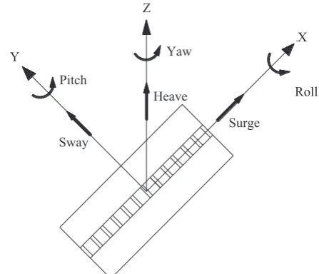
[image:3.595.51.267.570.732.2]The experiments were carried out in both oblique and beam sea conditions. The water depth during the model tests is 1.0 m. At beam sea condition,y-axis of thefloating system is parallel to the wave propagation direction (as shown inFig. 8) while the angle betweeny-axis and the wave direction is 22.5°(as shown inFig. 9) at the oblique wave condition. Considering the environmental parameters in South China Sea, 44 wave conditions with different wave height and period are taken into consideration in both ob-lique and beam wave.Table 4shows the parameters of the regular waves.Fig. 10describes the six-degree of freedom movement for floating breakwater.
4. Analysis method
Goda and Suzuki (1976)proposed a two-point method to se-parate the reflected waves and the incident waves with the same wave period by examining the measured wave heights. The method can be used for both regular and irregular waves. In the
[image:4.595.122.479.58.265.2]present experiment, WG2 and WG3 are used to separate the in-cident and reflected waves in front of thefloating system to obtain the amplitudeAiandAr, while WG4 and WG5 are used to separate the transmitted wave after thefloating system to obtain the am-plitudeAt. Reflection coefficientKr, transmission coefficientKtand dissipation coefficientEdcan be expressed as:
[image:4.595.144.465.300.422.2]Fig. 3.Sketch offloating breakwater.
Fig. 4.Thefloating breakwater.
[image:4.595.142.466.451.636.2]=A A ( )
Kr r/ i 1
=A A ( )
Kt t/ i 2
= −K –K ( )
Ed 1 r2 t2 3
As for the 6-DOF motion responses, the time domain analysis is used. The motion amplitude of thefloating breakwater is defined as the oscillation amplitude relative to its mean position in waves. For example,
surge amplitude¼(maximum surge amplitude-minimum surge amplitude)/2.
In fact, the majority of data are valid despite that there are few data which was subjected to signal interference. However, those interfered data will not be used in this paper.
5. Results and discussions
5.1. Wave transmission coefficients
[image:5.595.43.275.60.611.2]The efficiency of wave dissipation of the floating breakwater system is estimated by its wave transmission coefficientKt.Fig. 11 shows the wave transmission coefficients of the system in beam and oblique waves with different wavelengths. Thex-axis of the figure is the nondimensionalized wavelengthL/B, whereLis the wavelength andBis the breadth of thefloating breakwater system. It can be observed fromFig. 11that both in beam and oblique wave conditions, theKtcurves have a similar trend with each other. As the wavelength increases, Kt increases almost linearly against wavelength atL/Bo6.5. It reaches its peak atL/B¼6.5 for all three different wave heights. Afterward, asL/Bbecomes larger than 6.5, the wave transmission coefficients turn to have downward trend against wavelength. This is a very interestingfinding which has not been demonstrated in the published results. In the previous literatures, the breakwater has very poor behavior as the wave length becomes very large. However, some results from the mo-tions support thisfinding. For example, the heave, pitch and yaw motion amplitude keep increase asL/B46.5. The large amplitude oscillating of the breakwater disperses more energy, which could be one of the reason why a downward trend ofKtcan be found whenL/B46.5. Of course, a detail study about the wave trans-mission in long waves is desired both in numerical and theoretical method. It can also be observed fromFig. 11 that at H/h¼0.32 (where H/his the ratio of wave height to FB height), the wave transmission coefficient of the FB is larger than that of the other two values of H/h. But it does not mean the smaller H/h can transmit more wave energy.
Fig. 12shows the wave transmission coefficients of the system in beam and oblique waves with different wave heights, where the wave height is nondimensionalized by the height of thefloating cylinder. Two typical wavelengths (L/B¼2.5 and L/B¼6) are se-lected in order to investigate the effect of wave heights. Generally, the effect of wave height on wave transmission is not very evident. In short waves(L/B¼2.5), more wave energy can be transmitted when the wave height is small. As the wave height increases,Kt has a slight downward trend, which indicates that the FB system Table 1
Main parameters of cylindricalfloating breakwater.
Length(m) l 1.5
Breadth(m) B 0.625
Height(m) h 0.25
Draft(m) d 0.125
Mass(kg) M 70.03
Gravity center above bottom(m) t 0.125 Roll inertia(kg*m2
) Ixx 3.22
Pitch inertia(kg*m2) I
yy 14.25
Yaw inertia(kg*m2) I
[image:5.595.37.280.76.353.2]zz 16.63
[image:5.595.71.249.367.617.2]Fig. 6.Three parts of the mooring line.
Fig. 7.Experimental spring.
Table 2
Natural period of motions (L is the wave length and B is the breadth of FB unit).
DOF Surge Sway Heave Roll Pitch Yaw
Period (s) 3.32 1.42 1.47 0.92 1.26 4.74 L/B 15.62 4.88 5.18 2.11 3.92 23.05
Table 3
Main parameters of the mooring lines.
Diameter Length Axial rigidity
The submerged weight per unit length
(mm) (m) (KN) (g*m1
)
[image:5.595.30.283.659.702.2]has better performance in short waves with larger wave heights. However, due to the limitation of the wave-maker, we cannot extend the wave height to any larger values. On the other hand, in short waves, when the ratio of wave height to wavelength is very large, the waves will be determined by the nonlinear theory, which is beyond our consideration. In long waves (L/B¼6), the
[image:6.595.122.484.56.265.2]Fig. 8.Beam regular wave,β¼0°.
Fig. 9.Oblique regular wave,β¼22.5°.
Table 4
Parameters of the regular wave condition.
Wave heightH/m Wave periodT/s wave incident angleβ (°)
A1-A12 0.08 0.8–1.9 with step at0.1
0, 22.5
A13-A22 0.15 1.0–1.9 with step at 0.1
0, 22.5
A23-A30 0.25 1.2–1.9 with step at 0.1
0, 22.5
A31-A35 0.08–0.16 with step at 0.02
1 0, 22.5
A36-A44 0.10–0.26 with step at 0.02
1.6 0, 22.5
[image:6.595.322.546.527.719.2] [image:6.595.43.293.551.672.2]wave transmission coefficients are much larger than those in short waves in the full range of wave heights. As the wave height in-crease, the Kt has a slight downward trend until it reaches its minimum value at H/h¼0.7, followed by a slight upward trend. However, the minimum wave transmission coefficient is 0.8, which is still very large in long waves.
It can be concluded fromFig. 11andFig. 12that the cylindrical breakwater system is able to reflect most of the short waves. Therefore, it is very effective in short wave condition for a wide
[image:7.595.77.511.59.227.2] [image:7.595.76.510.259.427.2]range of wave heights. In case of long waves, most of the wave energy is transmitted. As the wavelength keeps increasing, the transmission coefficient will drop down. This is a desirable phe-nomenon especially when the breadth of the FB is small. In this case, the wavelength to breadth ratio could be very large (probably it can exceed the ratio where the peak Kt is achieved) and the efficiency of the FB is still satisfactory. However, the maximum wavelength to breadth ratioL/Bin the present experiment is less than 8 due to the large breadth of the present FB model. A further Fig. 11.Transmission coefficients of FB system in waves with different wavelengths. (a) Beam wave condition; (b) oblique wave condition.
Fig. 12.Transmission coefficients of FB system in waves with different wave heights. (a) Beam wave condition; (b) oblique wave condition.
[image:7.595.77.509.460.628.2]investigation ofL/B48 will be carried out in the future to see the range of this downward trend. With regard to the incident wave angle, the difference of the wave transmission coefficient is very small between the beam and oblique conditions. It indicates the present FB system has a satisfactory performance both in beam and oblique wave conditions.
5.2. Wave energy reflection coefficients
Wave reflection is an important way for the floating
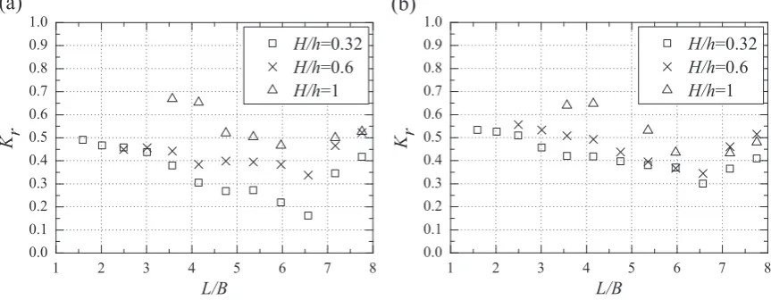
[image:8.595.85.519.61.226.2] [image:8.595.88.519.259.419.2]breakwaters to attenuate the wave energy.Fig. 13shows the wave reflection coefficients of the system in beam and oblique waves with different wavelengths. It can be observed fromFig. 13that the trend of theKrcurves is consistent in both beam and oblique wave conditions. At L/Bo6.5, the wave reflection coefficient curves generally keep a downward trend. But the slopes of the curves of different wave height are various. In beam waves, Kr curves decease rapidly with the increase of the wavelength atH/h¼0.32 andH/h¼1. But the drop ofKrcurves atH/h¼0.6 is not very ob-vious. With regard to the oblique wave condition, the downward Fig. 14. Reflection coefficients of FB system in waves with different wave heights. (a) Beam wave condition; (b) oblique wave condition.
Fig. 15.Dissipation coefficients of FB system in waves with different wavelengths. (a) Beam wave condition; (b) oblique wave condition.
[image:8.595.85.518.450.616.2]trend ofKrcurves is mild. However, the wave reflection coeffi -cients turn to increase after they reach their minimum value atL/ B¼6.5. It is most possibly due to the severe sway motion, which can reduce the wave reflection. It can be found that the sway motion gets the peak response at L/B¼6.5 in Fig. 17(b). It also shows that the wave transmission coefficient gets the largest value when the wave reflection coefficient gets the smallest value by comparing Fig. 13with Fig. 14. So it can be concluded that the motion period of the sway of the FB is very important to the wave attenuation effectiveness and it can be obtained byTable 2. It can also be observed fromFig. 13that atH/h¼1, the wave reflection coefficient of the FB is larger than that of the other two values ofH/ h.It means the largerH/hthe more waves can be reflected by the floating breakwater system.
Fig. 14shows the wave reflection coefficients of the system in beam and oblique waves with different wave heights. It can be observed that the effect of wave height on reflection coefficients is not very evident for short waves (L/B¼2.5) in both beam sea and oblique sea conditions. However, in the long waves (L/B¼6), the reflection coefficients in beam waves are quite different from those in oblique waves. In beam waves, the reflection coefficients increase significantly with the increase of the wave height before reaching its peak atH/h¼0.88. Afterward, asH/hbecomes larger than 0.88, the wave reflection coefficients keep stable. In oblique waves, as wave height increases, reflection coefficients keep a slow growth.
[image:9.595.75.513.57.561.2]waves, which indicates that the present FB system has a better performance in reflecting waves in oblique wave condition.
5.3. Wave energy dissipation coefficients
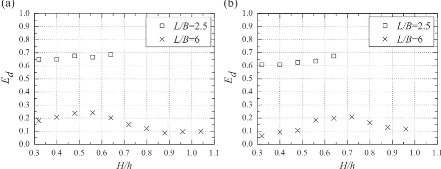
Fig. 15shows the wave dissipation coefficients of the system in beam and oblique waves with different wavelengths. It can be observed fromFig. 15that both in beam and oblique wave con-ditions, theEdcurves have a similar trend with each other. ForL/ Br6,Eddecreases rapidly as the wavelength increases. Afterward, as wavelength increases, wave dissipation coefficient has a slight growth for L/BZ6.57. This can be explained by the motion re-sponses of the system. The motion rere-sponses of the floating
breakwater in 6 DOF all experience a trend of decrease at L/ BZ6.57 (as shown inFig. 17andFig. 18). In addition, for all wave conditions, wave dissipation coefficientsEdatH/h¼0.6 is greater than the other two wave heights while the smallestEdis observed atH/h¼1.
[image:10.595.85.521.55.575.2]However, the peak value in beam waves appears at H/h¼0.55, while in oblique wave, it turns to be atH/h¼0.7.
5.4. Motion responses
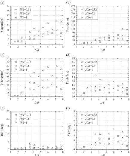
Fig. 17shows the relationship between module's six-degree of freedom motion responses and wavelength in beam waves. In case of three translational motions (surge, sway and heave motion), there is a spike appears atL/B¼4.76 for surge and sway. Due to the incident wave angle, the sway in beam waves has the largest amplitude. And atL/B¼6.57, the sway motion achieves a very large value. However, the peaks atL/B¼4.76 and 6.57 are not due to the natural frequencies. Of course, the natural frequency is very
[image:11.595.76.511.55.573.2]two others in beam waves. It can be seen fromFig. 17(e) that the amplitude of roll motion grows untilL/B¼4.76 and then followed by a downward trend. It is expected that the surge, pitch and yaw motion should be zero due to the incident wave condition. How-ever, due to the coupled behaviors between the FB units and be-tween the FBfloaters and mooring lines, these degrees of motion are still noticeable. However, the amplitudes of these degrees of motions are relatively small compare the rest of the degrees of motion.
Fig. 18shows the motion responses against the wavelength in oblique waves. Generally, the conclusions in oblique waves are similar to these in beam waves. There are two spikes observed at
L/B¼4.76 and 6.57 respectively.
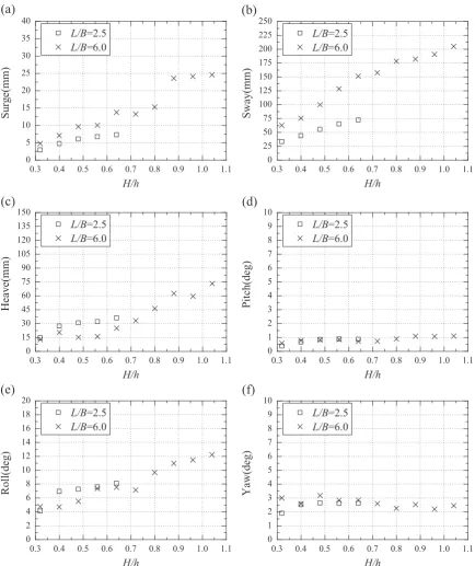
Fig. 19shows the motion responses against the wave height in beam waves. Based on linear assumption, the motion responses are expected to have a linear relation with the wave height. But this linear relation has not been observed fromFig. 19. With regard to the surge, heave and sway motions, which are most violate in beam sea waves, the motion amplitudes increase nonlinearly against the wave amplitude. This nonlinear results is due to the large amplitude of the incoming waves. And this nonlinear rela-tion is most obvious at wave height range of 0.6oH/ho0.8.
[image:12.595.87.522.58.590.2]except yaw and surge response, as shown in Fig. 20. At wave height range ofH/h40.9, the yaw response amplitude increases dramatically. With regard to the three translational motions, the motion response amplitude at large wavelength is much larger than that at short waves. But this conclusion cannot cover the pitch and roll motions.
6. Conclusion
In the present paper, we conducted a 3D experiment to in-vestigate an innovative floating breakwater system. The perfor-mance of the FB system was estimated by measuring the wave transmission coefficients, wave dissipation coefficients and six-degree of freedom motion responses. These measurements are influenced by the factors of wavelength, wave height and incident wave angle. According the experimental measurements, some conclusions are shown as follows:
(1) The proposed cylindricalfloating breakwater system is able to dissipate most of the short waves in both beam and oblique wave conditions. In case of long waves, most of the wave energy is transmitted. As the wavelength keeps increasing, the transmission coefficient will drop down. This is a desirable phenomenon for the engineering practice, especially when the breadth of the FB is small.
(2) With the increase of the wavelength, the motion response amplitude of the FB system suffers an increase before it reaches its peak value, followed by a decrease trend. As the wave amplitude increases, the motion response amplitude increases nonlinearly due to the nonlinearity of the large amplitude incident waves and coupled behavior between the FB units and mooring lines. The sway period of the FB is very important to the wave attenuation effectiveness In order to ensure the wave attenuation effectiveness, the sway period of the FB should be designed to avoid the most possible wave frequency at certain sea condition.
In summary, by examining the wave transmission coefficients and the motion responses, it can be concluded that the proposed FB system has a satisfactory performance and it can be used to a wide range of sea conditions, including South China Sea.
Acknowledgments
This study was supportedfinancially by the National Natural Sci-ence Foundation of China (Grant no.51379095) and the National Basic Research Program of China (973 Program; Grant no.2013CB3610 0).
Appendix A. Supplementary material
Supplementary data associated with this article can be found in the online version athttp://dx.doi.org/10.1016/j.oceaneng.2016.07.051.
References
Abul-Azm, A.G., Gesraha, M.R., 2000. Approximation to the hydrodynamics of
floating pontoons under oblique waves. Ocean Eng. 27 (4), 365–384. Arunachalam, V.M., Raman, H., 1982. Experimental studies on a perforated
hor-izontalfloating plate breakwater. Ocean Eng. 9 (1), 35–45.
Bayram, A., 2000. Experimental study of a slopingfloat breakwater. Ocean Eng. 27 (4), 445–453.
Chen, Z.J., Wang, Y.X., Dong, H.Y., Zheng, B.X., 2012. Time-domain hydrodynamic analysis of pontoon-platefloating breakwater. Water Sci. Eng. 5 (3), 291-30. Dong, G.H., Zheng, Y.N., Li, Y.C., Teng, B., Guan, C.T., Lin, D.F., 2008. Experiments on
wave transmission coefficients offloating breakwaters. Ocean Eng. 35, 931–938. Gesraha, M.R., 2006. Analysis ofΠshapedfloating breakwater in oblique waves: I.
Impervious rigid wave boards. Appl. Ocean Res. 28 (5), 327–338.
Goda, Y., Suzuki, Y., 1976. Estimation of incident and reflected waves in random wave experiments. In: Proceedings of the 15th International Conference on Coastal Engineering. ASCE. pp. 828–845.
Hanif, M., 1983. Analysis of heaving and swaying motion of afloating breakwater by
finite element method. Ocean Eng. 10 (3), 181–190.
He, F., Huang, Z., Law, A.W., 2012. Hydrodynamic performance of a rectangular
floating breakwater with and without pneumatic chambers: an experimental study. Ocean Eng. 51, 16–27.
Ji, C.Y., Chen, X., Cui, J., et al., 2015. Experimental study of a new type offloating breakwater. Ocean Eng. 105, 295–303.
Koraim, A.S., 2015. Mathematical study for analyzing caisson breakwater supported by two rows of piles. Ocean Eng. 104, 89–106.
Koraim, A.S., Rageh, O.S., 2013. Effect of Under Connected Plates on the Hydro-dynamic Efficiency of the Floating Breakwater. Ocean Eng. 28 (3), 349–362. Loukogeorgaki, E., Michailides, C., Angelides, D.C., 2012. Hydroelastic analysis of a
flexible mat-shapedfloating breakwater under oblique wave action. J. Fluids Struct. 31, 103–124.
Loukogeorgaki, E., Yagci, O., Kabdasli, M.S., 2014. 3D Experimental investigation of the structural response and the effectiveness of a mooredfloating breakwater withflexibly connected modules. Costa. Eng. 91, 164–180.
Martinelli, L., Ruol, P., Zanuttigh, B., 2008. Wave basin experiments onfloating breakwaters with different layouts. Appl. Ocean Res. 20, 199–207.
McCartney, B.L., 1985. Floating breakwater design. J. Waterw., Port., Coast., Ocean Eng. 111 (2), 304–317.
Najafi-Jilani, A., Rezaie-Mazyak, A., 2011. Numerical investigation offloating breakwater movement using SPH method. J. Nav. Archit. Ocean Eng. 3, 122–125. Ozeren, Y., Wren, D.G., Altinakar, M.S., Work, P.A., 2011. Experimental investigation of cylindricalfloating breakwater performance with various mooring confi g-urations. J. Waterw. Port. Coast. Ocean Eng. 137 (6), 300–309.
Peña, E., Ferreras, J., Sanchez-Tembleque, F., 2011. Experimental study on wave transmission coefficient, mooring lines and module connector forces with different designs offloating breakwaters. Ocean Eng. 38, 1150–1160. Peng, W., Lee, K.H., Shin, S.H., Mizutani, N., 2013. Numerical simulation of
inter-actions between water waves and inclined-moored submergedfloating breakwaters. Coast. Eng. 82, 76–87.
Ragih, O.S., El-Alfy, K.S., Shamaa, M.T., Diab, R.M., 2006. An experimental study of sphericalfloating bodies under waves, In: Proceedings of 10th International Water Technology Conference (IWTC10), Alexandria, Egypt, pp. 357–375. Rahman, M.A., Mizutani, N., Kawasaki, K., 2006. Numerical modeling of dynamic
responses and mooring forces of submergedfloating breakwater. Coast. Eng. 53, 799–815.
Sannasiraj, S.A., Sundar, V., Sundaravadivelu, R., 1995. The hydrodynamic behavior of longfloating structures in directional seas. Appl. Ocean Res. 17 (4), 233–243. Sannasiraj, S.A., Sundar, V., Sundaravadivelu, R., 1998. Mooring forces and motion
responses of pontoon-typefloating breakwaters. Ocean Eng. 25 (1), 27–48. Stamos, D.G., Hajj, M.R., Telionis, D.P., 2003. Performance of hemi-cylindrical and
rectangular submerged breakwaters. Ocean Eng. 30 (6), 813–828.
Wang, H.Y., Sun, Z.C., 2010. Experimental study of a porousfloating breakwater. Ocean Eng. 37, 520–527.
Williams, A.N., Abul-Azm, A.G., 1997. Dual pontoonfloating breakwater. Ocean Eng. 24 (5), 465–478.
Zheng, Y.H., Shen, Y.M., You, Y.G., Wu, B.J., Jie, D.S., 2006. Wave radiation by a