An improved engine analysis and optimisation tool for
hypersonic combined cycle engines
A. Mogavero
∗R. E. Brown
†Centre for Future Air-Space Transportation Technology,
University of Strathclyde, Glasgow, G1 1XJ, United Kingdom
It is widely accepted that more efficient propulsion technology needs to be developed be-fore the re-usable ‘space plane’ concept for cheap and reliable access to space can become a practical reality. An engineering tool, called the HYbrid PRopulsion Optimiser, or HyPro for short, has been developed to characterise and optimise the performance of a range of hy-personic propulsion systems, with particular application to air-breathing and hybrid engines. The level of modelling embodied in the tool is particularly appropriate to the rapid paramet-ric studies and configurational trade-offs that are usually conducted during the preliminary design of the propulsion system and the hypersonic vehicle that it is intended to propel.
An algorithm, based on the Genetic Programming approach, and exploiting the highly modular structure of the engine model, has been developed to search the configurational design space for the engine geometry that is best adapted to the mission for which it is intended. In contrast to conventional optimisers which can vary only the parameters of the engine design, this tool is able to provide design solutions for the propulsion system without the actual structure of the engine having been specifieda priori. Several applications serve to demonstrate the value of the tool in introducing some degree of objectivity into the process of discriminating between the many different configurations that have been proposed for space plane propulsion in the past.
I.
Introduction
Decades after the first pioneering years of space exploration, there is still a large margin for improve-ment within the field of space transportation tech-nology. In particular, the development of a new, ef-ficient means of access to space would yield a giant leap in the viability of the many proposals for space exploitation and exploration that are currently be-ing considered. One possible strategy for makbe-ing access to space cheaper, more flexible and reliable is to implement the Single-Stage to Orbit (SSTO) concept. The idea is to supplant current expendable launch vehicle technology by developing a class of re-usable ‘space planes’ that are able to reach or-bit and then re-enter the atmosphere by following a mission profile that is very similar to that used by airliners.
The technological challenges of putting this very simple idea into practice are significant, however, given the complexity of such a system in reality. Further development of propulsion technology is fundamental to yielding a practical SSTO system.
Air-breathing propulsion systems are inherently limited in terms of the speed and altitude at which they can function reliably. Any vehicle that is in-tended to fly into space thus requires some addi-tional means of propulsion once it has accelerated to speeds and altitudes that lie beyond the limits of its air-breathing propulsion system. One solution is to introduce engine technology that combines a number of different propulsion technologies, for ex-ample jets and rockets. The design of such hybrid propulsion systems is very challenging indeed, not least because appropriate performance over a broad operational range must not come at the expense of significant increases in engine weight or greatly re-duced systems reliability.
Selection of the appropriate system architecture in the early stages of the engine design is held by most designers to be critically important to the likely success of the vehicle that it is intended to propel, and in many cases the configuration of the propulsion system actually defines the operational paradigm for its parent vehicle. When considering future space access vehicles, many radically differ-ent configurations for the propulsion system have been considered, suggesting perhaps that the range of viable engine designs is actually quite broad. For these reasons, a very valuable asset to the design process would be a tool that could point the de-signer towards the engine geometry that is best adapted to the mission for which it is intended. This would especially be the case if the tendency could be obviated for the designer to embed into the process his/her own prior assumptions, prefer-ences or prejudices as to the structure of the engine.
The final aim of the research described here is to achieve this lofty goal, in other words to create a tool that, given a certain set of operational re-quirements, would, for instance, be able to choose, based on objective and repeatable heuristics, be-tween various possible design solutions or, perhaps, in the best of all worlds, would be able to create a wholly new engine concept that suits the opera-tional needs of the vehicle better than any configu-ration previously thought of by the human designers of the system.
In this paper, an updated version of the Hybrid Propulsion Parametric-Modular Model (HPPMM), first introduced in an earlier work by the current authors,2 is described. The principal feature of
this new version of the model, called the HYbrid PRopulsion Optimiser (HyPro), is the introduction of an algorithm, based on the Genetic Programming (GP) approach, that can search the configurational design space for the engine geometry that is best adapted to the mission for which it is intended. In
contrast to conventional optimisers which can vary only the parameters of the engine design, this tool is intended to be able to provide design solutions for the propulsion system without the actual structure of the engine having been specifieda priori. An ap-plication of the model is then presented to demon-strate the value of the tool in providing at least the beginnings of an approach whereby some degree of objectivity can be introduced into the process of discriminating between the many different config-urations that have been proposed for space plane propulsion in the past.
As a brief note on terminology: throughout the current paper, the term ‘hybrid’ is taken to refer to any possible combination of propulsion technol-ogy, either when installed separately or when inte-grated into a single engine system. Usually the for-mer is calledcombination propulsionand the latter is calledcomposite propulsion3or, more frequently,
combined cycle propulsion.4
II.
Engine Performance Model
The HyPro software works by discretising the configuration of the propulsion system into a se-quence of interconnected blocks, or modules, each representing one or more components of the engine. Information can flow between the modules to repre-sent the relationship between the inlet parameters for one module, for instance, and the outlet param-eters of the modules to which it is physically con-nected. Figure 8 shows the model configured as a simple ramjet/scramjet, for instance, while Fig. 5 shows the model configured as a rocket-based com-bined cycle engine.2 A set of coupled equations for
the thermodynamic properties within each of the interconnected modules can then be solved, and the overall performance characteristics of the en-gine can then be extracted through the appropri-ate mass, momentum and energy balances. To-gether with having been translated from the origi-nal MatlabR of the HPPMM into C++ in order to
improve the computational efficiency and execution speed of the software, the new version of the model contains several additional modules as well as some improvements in physical modelling within its exist-ing modules. Although the details of the approach are described more completely elsewhere,2 as is the
II.A. Gas dynamic models
The main fluid dynamics models implemented in HyPro are the same as those used in HPPMM:
• isentropic one-dimensional compres-sion/expansion5
• Fanno flow5
• Rayleigh flow5
• One dimensional balance equation solver2
N1 N2
Inlet
[image:3.612.350.538.527.584.2]Outlet
Figure 1. Definition of stations for a one-dimensional duct with variable cross-sectional area.
In HyPro, however, the isentropic compres-sion/expansion model has been improved in order to account for gases that are not thermally perfect (i.e. those that have variable ratio of specific heats
γ). As done in HPPMM, the Mach number at the outlet of any duct, the cross-sectional area of which varies along its length as shown in Fig. 1, is cal-culated iteratively after imposing a mass balance between the inlet and the outlet. During the iter-ative process, all the thermodynamic conditions at the outlet node (i.e. node N2 in Fig. 1) are
calcu-lated assuming the flow to be isenthalpic and isen-tropic, but, in HyPro, the simple set of equations used in HPPMM to model isentropic expansion or compression5are replaced with a two-step iterative calculation. Firstly, the static temperature at node
N2 is calculated from the energy equation
h2+
M2 2a22
2 =h1+
M2 1a21
2 . (1)
In this equation, only h2 and a2 are initially
un-known, but both are functions of the temperature
T2, which can then be determined through iteration.
The static pressure at node N2 is then calculated
from the entropy equation6
So(T2)−Rln
p2
po =S o(T
1)−Rln
p1
po. (2)
The pressurep2 is the only unknown in this
equa-tion once the inlet condiequa-tions are specified. It should be noted that Eq. 2 is only valid for gases with constant composition, and this requires the assumption that the chemical composition of the
working fluid is frozen in all the modules that use this analysis (i.e. the ‘inlet’, ‘nozzle’, ‘diffuser’, etc., as presently implemented in HyPro). Despite this restriction, the new formulation has the major ad-vantage of removing many of the inaccuracies in the analysis that are introduced by assuming the work-ing fluid to have constantγ, and indeed allows the analysis to be extended to a wide range of work-ing fluids that are governed by very different gas models. In the present context, this improvement in modelling has proved to be particularly benefi-cial in preventing the Genetic Programming (GP) algorithm described later from exploiting small nu-merical errors in the fluid dynamic solver to gener-ate spurious, vastly complicgener-ated configurations with seemingly much improved performance compared to their competitors.
II.A.1. Balance equation solver
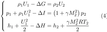
A generalised module exists within the software in order to solve the coupled set of equations
ρ1U1−∆G=ρ2U2
p1+ρ1U12−∆I=p2+ρ2U22
h1+
U12
2 −∆H =h2+
U22
2
(3)
representing, respectively, the balance of mass, mo-mentum and energy along a duct that has constant cross-sectional area. In these equations, ∆G, ∆I
and ∆H represent respectively the flux of mass, momentum and energy across the walls of the duct. The solver attempts to determine the conditions at the end of the duct (i.e. at state 2) given the con-ditions at the beginning of the duct (i.e. at state 1) and these lateral fluxes. In order to simplify the solution, the system of equations is rewritten, in terms of the Mach number in the duct, as
ρ1U1−∆G=ρ2U2
p1+ρ1U12−∆I= 1 +γM 2 2
p2
h1+
U2 1
2 −∆H =h2+
γM2 2RT2
2
(4)
It is important to note that the only assumption needed to support the validity of this set of equa-tions is that the gas be ideal in its behaviour. Con-sistently with the formalism used for variable-area ducts as described earlier, the ratio of specific heats
γ can thus be modelled as a function of tempera-ture. The solution process starts by proposing a tentative value for M2 and then proceeds through
The momentum equation is then used to determine the static pressure p2. Finally the mass balance
equation is used to check whether the tentative value assumed for M2 yields a solution that
con-serves mass, momentum and energy between the inlet and the exit to the duct. If not, the whole pro-cedure is iterated by means of a bisection algorithm until the desired level of convergence is reached.
II.B. Rocket injection module
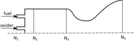
A new model for fluid injection has been added in HyPro with the aim of describing in more detail and with more accuracy the flow physics, specif-ically within rocket engines, than was possible in older versions of the software. A rocket engine is created by combining a combustion chamber mod-ule and a nozzle modmod-ule with the injection modmod-ule as shown in Fig. 2 (where injection takes place be-tween nodesN1 andN2). The module requires the
composition of the working fluid, the total mass flow rate, the Mach number, and the static temperature at nodeN2 to be specified externally.
N1 N2 N3 N4
fuel
[image:4.612.350.543.151.227.2]oxider
Figure 2. Definition of stations for the rocket injection module (as implemented in a typical rocket engine model).
II.C. Mixer module
The mixer module within HyPro allows the mixing of two flows to be modelled. Its definition requires an additional internal node (N3in Fig. 3) which can
be joined to any other type of module within the HyPro toolbox. This module is typically used when the momentum of the flow exiting the module that is attached to the internal node cannot be neglected.
N1 N2
N3
θ
Figure 3. Definition of stations for the mixer module.
The mixer module uses the balance equation solver described in Section II.A.1 to obtain the flow
properties at node N2 given the flow properties
at nodes N1 and N3. To satisfy the parallel-flow
assumption embodied within the balance equation solver, the area of the duct at node N1 must of
course be made equal to the area of the duct at node N2. The fluxes of mass, momentum and
en-ergy into the duct are calculated as
∆G=−A3
A1
ρ3U3
∆I=η
∆GU3−
A3
A1
(p3−p1)
cosθ
∆H = ∆G
U2 3
2 +h3
(5)
where η is the mixer efficiency and θ is the angle at which the flow is injected into the mixer at the internal node (see Fig. 3). This set of equations is derived under the assumption that the pressure sur-rounding the injected flow is equal to the pressure at nodeN1; this can be assured if the mixer
mod-ule is defined so that its inlet is close to the point of injection.
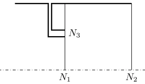
This assumption is weak whenever the cross-sectional area over which fluid is injected (i.e. the area at node N3) is large compared to the total
area of the mixer duct (i.e. the area of the duct at node N2). Where necessary, this problem can
be overcome by modifying slightly the formulation presented above. If it is assumed that the two mix-ing flows start by bemix-ing parallel, then nodesN1and
N3(see Fig. 4) can be made coincident and only the
flow downstream of the injection point needs to be modelled. This assumption of course requires the slightly more restrictive constraint that the area of the duct atN2be equal to to the sum of the duct
ar-eas atN1andN3so that the assumption of parallel
flow that is embodied within the balance equation solver remains valid. In addition, the back pres-sure acting on any component attached to nodeN3
(e.g. the pressure within the connector pipe shown Fig. 4) can be eliminated as an unknown simply by rendering this node external to the control volume used in the analysis. In the resultant ‘parallel flow mixer’ module, the expressions for the mass, mo-mentum and energy fluxes into the duct can thus be written as
∆G=−A3
A2
ρ3U3
∆I=η
∆GU3−
A3
A2
p3
∆H = ∆G
U2 3
2 +h3
.
[image:4.612.71.295.334.405.2] [image:4.612.97.269.576.659.2]N2
N3
N1
Figure 4. Definition of stations for the parallel flow mixer module.
II.D. Multi-mode system
A further improvement that has been implemented in HyPro is the possibility to model engines that can be operated in one of several modes depend-ing on the operatdepend-ing conditions in which the sys-tem finds itself. The logic that is used to define the switching between engine modes is typically based on the free stream conditions for the system, and is implemented in most cases by setting the appro-priate Mach number and total pressure ranges for each operational mode of the propulsion system. It is also possible to overlap the operational ranges of the various engine modes, and in this case the tran-sition between modes is achieved with the aid of a pre-defined schedule of priorities for all possible modes at each operating condition of the system.
III.
Verification of the Predictions
of the HyPro Model
Validation against real-world data of the predic-tions of a model such as HyPro is of course an im-portant element in establishing its value to the en-gineering community, none the more so given the simplicity of its representation of the physics within the engine system and the heavy reliance of the va-lidity of its predictions on the accuracy with which its internal parameters can be specified. In prac-tice, the extent to which the validation process can be carried out is limited not least by the paucity of real test data against which the predictions of the model can be compared. This is particularly the case when it comes to the advanced engine config-urations for which the software has been designed.
Given the intended focus of this paper on the ex-ploration of the configurational aspects of advanced engine design, here the predictions of the HyPro model are simply calibrated against those of the Simulated Combined-Cycle Rocket Engine Analy-sis Module (SCCREAM)4, 7, 8 that is perhaps
bet-ter known and accepted by the community than the HyPro model itself. In illustrating that HyPro is able to reproduce similar results to this
‘indus-try standard’ model, at least for the performance of those few engine configurations for which pub-lished data is available, the intent here is to provide support for a contention that is fundamentally nec-essary to the thesis of this paper but that remains essentially unproven – namely that HyPro contin-ues to provide physically-plausible predictions of the performance of engine systems that have con-siderably greater complexity than those for which verification is presented here (see Section IV of this paper, for instance). Admittedly the acceptance of the validity of this contention requires the reader to extrapolate quite considerably from the data pre-sented here; the authors are aware of this and hope-fully will be judged to have proceeded with due re-spect for this limitation in their analysis. In terms of more direct validation, the inquisitive reader is referred to the earlier paper by the current authors2
where the predictions of the model were compared against CFD data for scramjet and rocket-ejector type systems – with encouraging results.
To lend support to the veracity of HyPro’s predic-tions, its output is compared below to SCCREAM predictions of the performance of the hybrid propul-sion system that was proposed for Hyperion, a launch vehicle conceived by the Aerospace Systems Design Laboratory at Georgia Tech.4 SCCREAM
predictions have been published4 for the
perfor-mance of this engine when operating in pure ramjet mode as well as when operating in ejector ramjet mode:
III.A. Hyperion engine in ejector mode
The HyPro model representing the ejector mode of the Hyperion propulsion system (reproducing the work of Olds4) is depicted in Fig. 5.
[image:5.612.108.256.51.137.2]Free
Stream Intake Diffuser Mixer
Rocket
Diffuser Injection Fuel
Combustion
[image:6.612.89.526.57.124.2]Chamber Nozzle Thrust
Figure 5. HyPro model of the Hyperion engine in ejector mode.
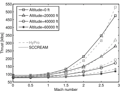
Mach number
Thrust [klbs]
0 0.5 1 1.5 2 2.5 3 50
100 150 200 250 300 350 400 450 500 550
Altitude=0 ft Altitude=20000 ft Altitude=40000 ft Altitude=60000 ft
HyPro
SCCREAM
Figure 6. Comparison between HyPro and SCCREAM predictions of the thrust of the Hyperion engine when in ejector mode.4
directly into the calculations within the mixer mod-ule. The flow then passes through a second isen-tropic diffuser. Injection then takes place, assuming constant equivalence ratio, followed by combustion. The equivalence ratio within the injection module can be reduced if choking is detected downstream of the injection point.2
In order to improve the correlation between HyPro and SCCREAM relative to that achieved with the older HPPMM software,2the modelling of
several phenomena within this engine has been up-graded. In all three models, the composition of the working fluid at the end of the combustion cham-ber is assumed to be the result of complete com-bustion, but in HyPro the possibility of incomplete combustion is accounted for by assuming a combus-tion efficiency of 0.80 (instead of unity as before) thus reducing the enthalpy of the flow downstream of the combustor. In addition, an 8% drop in the total pressure within the diffuser downstream of the mixer is also now accounted for in the HyPro repre-sentation of this engine. This is in addition to the mixer efficiency of 90% that is sensitively higher than that incorporated into the model as originally presented.2 In the absence anywhere in the open
literature of any explicit statement as to the val-ues that were adopted for these three parameters within the SCCREAM model of this engine, their
Mach number
Is
p
[
s
e
c
]
0 0.5 1 1.5 2 2.5 3
200 400 600 800 1000 1200 1400 1600
Altitude=0 ft Altitude=20000 ft Altitude=40000 ft Altitude=60000 ft
HyPro
[image:6.612.80.276.167.314.2]SCCREAM
Figure 7. Comparison between HyPro and SCCREAM predictions of the specific impulse of the Hyperion engine when in ejector mode.4
values within the HyPro model of the engine were simply tuned to give best direct agreement with the data presented by Oldset al.4
A comparison between the HyPro and SCCREAM predictions4 of the thrust and specific impulse for the Hyperion engine, when operated in ejector mode over an operationally-relevant range of altitudes and Mach numbers, is shown in Figs. 6 and 7. Overall, HyPro shows significant improvement in quantitative agreement with SCCREAM when compared to the predictions of the orginal HPPMM software2despite some rather
obvious differences in the qualitative behaviour of the two sets of predictions that are still quite clearly apparent.
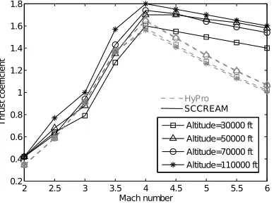
III.B. Hyperion engine in ramjet mode
The HyPro model representing the pure ramjet mode of the Hyperion propulsion system (again re-producing the work of Olds4) is depicted in Fig. 8.
[image:6.612.322.521.170.314.2]Free
Stream Intake
Constant
Area Duct Diffuser Injection Fuel
Combustion
[image:7.612.83.277.158.303.2]Chamber Nozzle Thrust
Figure 8. HyPro model of the Hyperion engine’s pure ramjet mode.
2 2.5 3 3.5 4 4.5 5 5.5 6
0.2 0.4 0.6 0.8 1 1.2 1.4 1.6 1.8
Mach number
Th
ru
s
t
c
o
e
ff
ic
ie
n
t
Altitude=30000 ft Altitude=50000 ft Altitude=70000 ft Altitude=110000 ft HyPro
SCCREAM
Figure 9. Comparison between HyPro and SCCREAM predictions of the specific thrust of the Hyperion engine in pure ramjet mode.4
to represent the losses within this part of the engine. All other modules are identical to those used to rep-resent the engine when in ejector ramjet mode.
The comparison between HyPro and SCCREAM predictions4for the thrust and specific impulse for
the Hyperion engine when operated in pure ramjet mode is shown in Figs. 9 and 10. Although there are larger qualitative and quantitative disagreements between the predictions of the two models than with the engine in ejector mode, both methods still yield predictions for the performance of the engine that are broadly in agreement.
Taken together, the results presented above for the relative performance of the HyPro and SCCREAM models when characterising the perfor-mance of the two relatively simple hybrid engine configurations analysed here yield a relatively com-plex picture. It is definitely the case that tuning of the internal parameters within the model has significant effect on the predictions of the models, and, indeed, if this tuning is done judiciously, then it is evident that the predictions of the two mod-els can be brought into quite close agreement with each other. Whether this is an advantage or a dis-advantage of this type of modelling remains open to debate, but the fact that this procedure is capa-ble of producing relatively good correlation between the two models across the majority of the perfor-mance envelope of the engine supports the inference
2 2.5 3 3.5 4 4.5 5 5.5 6 0
500 1000 1500 2000 2500 3000 3500 4000
Mach number
Is
p
[
s
e
c
]
Altitude=30000 ft Altitude=50000 ft Altitude=70000 ft Altitude=110000 ft
HyPro
[image:7.612.322.521.158.302.2]SCCREAM
Figure 10. Comparison between HyPro and SCCREAM predictions of the specific impulse of the Hyperion engine in pure ramjet mode.4
that both models represent the underlying physics within the propulsion system to roughly the same degree of inherent fidelity. Despite the tuning of the paramenters in the HyPro model specifically to match the predictions of SCCREAM as closely as possible, both sets of data presented above show the two models still not to match very closely in their predictions of the performance of the engine in cer-tain parts of its performance envelope. Although these remaining discrepancies seem most naturally attributable to differences in thedetailsrather than in thesubstance of the internal characterisation of the flow physics that is adopted by the two mod-els, this point of view cannot be fully substantiated without detailed insight into the structure of both models. Unfortunately this is not presently possible given the lack of published information relating to SCCREAM’s internal formulation.
in its essence, the methodology requires only an en-gine model that is sufficiently modular that it can represent all configurations of interest, that is ro-bust enough to actuallyproducea quantification of the performance of any candidate engine system no matter how contorted, bizarre or complex its con-figuration might be, and that can be relied upon to produce plausible, or at least correctly ranked, relative assessments of the performance of a set of competing engine configurations. Thus, despite the obvious ongoing need for further verification and validation of the HyPro model, when viewed in this context, the demonstrated agreement between the output of the new HyPro model and that of more established and accepted modelling procedures is, arguably, sufficiently good to support further devel-opment of the thesis of this work in the following sections of this paper.
IV.
Engine Configurational
Optimization
The problem of optimisation of the structural lay-out or configuration of the engine for its partic-ular operating conditions is complex. This is es-pecially the case given the potentially very large number of permutations that need to be consid-ered, the fact that very little may be known about the likely structure of the ideal engine, and that the designer may wish to introduce very little in-formationa prioriregarding the likely characteris-tics of the system for fear of contaminating, with his perconceptions, the eventual solution that is reached. This kind of problem can be handled very efficiently though, using a computational approach known as Genetic Programming (GP).9, 10, 11GP is
an evolutionary algorithm-based methodology, in-spired by biological evolution, that can be applied to the problem at hand to find engines with config-urations that are particularly well-adapted to the operating conditions in which they are expected to function. The GP approach is a specialisation of a more general formalism known as the Genetic Al-gorithm (GA) approach. In the GA approach a population of individuals, each representing a can-didate solution to the problem being analysed, is evolved through several generations. The survivors of this process are taken to be those that are best adapted to the conditions in which the population finds itself. Each individual is uniquely identified by the sequence of ‘genes’ that make up its ‘chromo-some’ – for instance, in GA, the chromosome might simply be comprised of the list of parameter values that uniquely define the particular individual. The population at generation i is produced firstly by
selecting a subset of the population at generation
i−1 that is best adapted to their environment (as ranked according to a problem-dependent ‘fitness function’) and then applying to this subset a se-quence of operators that are inspired by the process of biological natural selection. The most commonly used operators include ‘cross-over’, where the chro-mosomes of two individuals (parents) are combined to generate one or more (child) individuals, and ‘mutation’, during which random changes are made to parts of one individual’s chromosome.
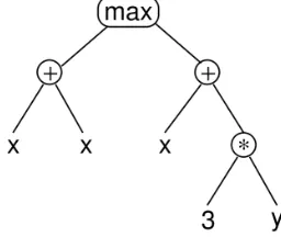
The main difference between GA and GP is that, in GA, the chromosome has a linear structure and a fixed length, whereas in GP the chromosome can have variable length and a tree-shaped structure (see, for example, Fig. 12). Each gene in any GP chromosome thus has one parent gene and one or more child genes. In Fig. 12, for instance, the ‘sum-mation operator’ gene, represented by the symbol ‘+’, has two children (In the left-hand case the sum-mands ‘x’ and ‘x’, and in the right-hand case the summands ‘x’ and ‘3*y’) and one parent (the re-sult of the summation). Because of the structural flexibility of its chromosomes, GP can be used to solve optimization problems without requiring the user to specify the structure of the solution in ad-vance.10 This key feature of the methodology en-ables the structure of the solution to the problem to evolve and thus potentially to change during the course of the calculation. In the engineering con-text, GP was initially applied to the optimisation of the internal structure of computer programs.10 It
has subsequently been applied to various problems in dynamical systems theory,12, 13 control systems
development,14 electronic circuit design15 and also
[image:8.612.365.493.531.639.2]to various problems in aerospace engineering such as the design of an antenna for the NASA Space Technology 5 spacecraft.16, 17
Figure 12. Example of a GP tree chromosome representing the expressionmax(x+x, x+ 3∗y)
inter-Nozzle Combustion
Chamber Injection
Inlet Feed-0
Feed-0
Feed-1
Gene Types
Module Addition
Feedback definition
Thrust Nozzle
Combustion Chamber Injection
Inlet Free
[image:9.612.112.529.57.272.2]Stream
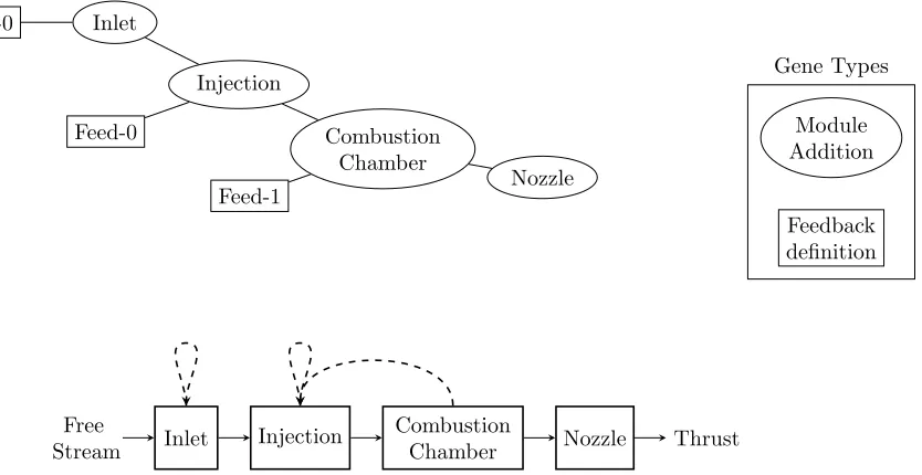
Figure 11. Mapping between an example GP tree chromosome (top) and its corresponding HyPro engine model (bottom).
connected modules, it is particularly amenable to forming the basis of a GP optimization methodol-ogy for the internal configuration of the propulsion system for hypersonic vehicles in much the same fashion as the electronic circuits or the dynamic systems were treated in the examples cited above. The approach used by Koza to optimise the layout of electronic circuits15 is most appropriate for this application, but some modifications to account for certain specifics of the engine modelling problem need first to be accounted for. As in the case of electronic circuits, not all engine configurations can be represented directly in terms of a tree-shaped chromosome (see for instance the structure shown in Fig. 8). This is particularly the case when the possibility of feedback between the modules that comprise the engine must be accommodated in the HyPro model (as is necessary for instance when the possibility of choking in one of the modules of the engine must be accounted for2). To obviate this
problem, Koza introduced a method calledcellular encoding,10 in which the GP genes represent a list
of instructions that modify an initial simple proto-type structure for the individual,10, 15 rather than representing directly the structure of the individual itself. While in the automated design of a complex electronic circuit many different instruction genes need to be coded for (for instance the addition of parallel components, serial components, and so on), in this work only two types of operation are defined in order to keep the exposition relatively straight-forward: the addition of one specified HyPro mod-ule, and the addition of feedback between two
spec-ified modules in order to represent the effects of choking at some point along the engine flowpath. The extension of the methodology presented here to more complex structural optimisation problems should however be quite readily apparent.
The mapping between an example GP chromo-some (consisting only of ‘module addition’ and ‘feedback definition’ genes as described above) and its corresponding HyPro representation of an en-gine configuration (here a simple ramjet/scramjet) is shown in Fig. 11. It is important to point out that not all chromosomes of this form correspond to physically feasible engine configurations, and this has important consequences for the evolution of any particular population of engine configurations. For instance, the module addition gene called ‘Combus-tion Chamber’ in Fig. 11 has has to have the module addition gene ‘Injection’ and a feedback definition gene as its children, whereas the feedback definition gene itself is terminal in the sense that it can have no children. As a result, a number of ‘type rules’ need to be obeyed during the evolution of the pop-ulation, leading to a strategy that is calledstrongly typed GPin the Genetic Programming jargon.10, 18
in later generations. The probability of survival of these non-viable forms from one generation to the next should however be rather low, and this bias in the selection procedure can be achieved by defining the probability of survival to be proportional to a fitness function of the form
fitness = max(0, T /m˙f) +fmin, (7)
for instance. In this way a small but non-zero prob-ability is assigned to the survival of even non-viable engine configurations from generation to genera-tion, thus preserving their chromosome as possible breeding material for a future population.
A final problem arises when a clearly superior configuration of engine is introduced as one of the population of configurations that is used to initiate the procedure. Because of the resultant very high probability of its subsequent selection, its chromo-some can come to dominate the gene pool in subse-quent generations. This so-called ‘seeding effect’10
amounts in the real world to nothing more than an overly-enthusiastic pre-conception of the final solu-tion to the problem of selecting the most approriate engine configuration, but this initial bias must be eliminated in the computational world by judicious selection a priori of the range of HyPro modules available to produce the starting population.
V.
Results
The GP formalism is implemented in HyPro using the Genetic Programming C++ Class Li-brary (GPC++) that is based upon the work of Koza.11, 10, 19 The library has been integrated into
HyPro after modification to allow strongly typed GP of the form described above. Results are pre-sented here showing the performance of the resul-tant algorithm in selecting the appropriate engine configuration for the propulsion of a typical space plane under two different but representative flight conditions, one supersonic and one subsonic.
The search space of the algorithm consists of the set of module addition genes (see Section IV) that allows all the modules used to represent the Hyperion engine, presented in Section III, to be in-cluded into the chromosomes of the members of the population. All module parameters are kept fixed throughout the computation. For the purposes of the demonstration, a stagnation pressure drop of 2% is applied between the inlet and outlet of all ‘in-let’, ‘diffuser’ and ‘nozzle’ modules and a friction co-efficient of 0.01 is applied within all ‘injection’ and ‘combustor’ modules. Finally, the ‘rocket’ module used in section III.B is supplanted with the more effective ‘injection’ module described in Section II,
in order to avoid the ’seeding effect’ described in section IV.
[image:10.612.322.536.268.382.2]The principal parameters of the optimization al-gorithm are listed in Table 1. A population of 300 engines is evolved for 20 subsequent generations. A maximum depth for the tree structure of the chromosome of each individual was imposed sim-ply in order to limit the complexity of the configu-rations that might emerge through evolution from the initial population. The probability of mutation in the examples presented here was kept non-zero but small in order to increase the diversity of the population. The relative fitness of the individuals within the population were assessed according to their specific impulseT /m˙f.
Table 1. Parameters for the GP algorithm.11
Population Size 300
Number of Generations 20
Maximum Tree Depth for Creation 6 Maximum Tree Depth for Crossover 17
Selection Type tournament
Tournament Size 20
Swap Mutation Probability 3.0% Shrink Mutation Probability 3.0%
V.A. Supersonic test case
As the first example of the application of this proce-dure, the engine that emerges from the evolution as most suited to supersonic flight conditions at Mach 2.5 at sea level (temperature 288.15 K and pres-sure 101.325 kPa) has the configuration shown in Fig. 13. It is quickly apparent that the engine has the configuration of a ramjet, albeit, most interest-ingly, one with several combustion chambers.
Nozzle Comb-8
Comb-7 Comb-6
Comb-5 Comb-4
Comb-3 Comb-2
Inj-1 Inlet-0
[image:11.612.71.540.53.102.2]Feedback
Figure 13. Supersonic test case: Configuration of the best engine of the last evolutionary generation.
0 0.5 1 1.5 2 2.5 3
Inlet−0−inInlet−0−outInjec−1−out
Comb−2−outComb−3−outComb−4−outComb−5−outComb−6−outComb−7−outComb−8−out Exit
Mach number
[image:11.612.82.280.153.293.2]Baseline Test−1 Test−2
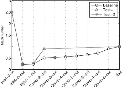
Figure 14. Supersonic test case: Variation of Mach number along the axis of the engine.
but with only one combustion chamber (denoted as Test-1), is slightly lower than that of the engine selected by the GP algorithm itself.
This behaviour can be explained by looking at Fig. 14, where the variation of Mach number along the axis of the engine is plotted. As can be seen, the Mach number always reaches the choking limit (here set conservatively to Mach 0.9 to account for unmodelled viscous effects in the engine2) at
the end of the last combustion chamber, but for the Test-1 configuration the combustion chamber is much shorter than that of the baseline configura-tion, so the pressure drop across it is also smaller. The lower friction allows more fuel to be injected into the Test-1 configuration before the choking limit is reached, as is demonstrated in Fig. 16, where it is clear that the jump in mass flow rate across the injection module of the Test-1 config-uration is bigger than in the baseline case. Fur-ther evidence of this effect can be found in Fig. 15, where the variation of static temperature is plotted along the axis of the engine. It can be seen that the post-combustion temperature is much higher in the Test-1 configuration than in the baseline case. This is simply because the conditions in its com-bustion chamber are closer to being stoichiometric. To prove this assertion, further data is presented in Table 2 for when the equivalence ratio of the injection module in the simplified Test-1 configu-ration has been lowered to 0.45, in other words to the value that is required in the baseline condition
500 1000 1500 2000
Inlet−0−inInlet−0−outInjec−1−out
Comb−2−outComb−3−outComb−4−outComb−5−outComb−6−outComb−7−outComb−8−out Exit
Static temperature [K] Baseline
Test−1 Test−2
Figure 15. Supersonic test case: Variation of temperature along the axis of the engine.
in order to induce choked conditions at the end of the combustion chamber. The fitness of this en-gine (or, in real terms, its specific impulse) is higher than that of both the Test-1 and the baseline en-gine configurations. Interpreting these results, the process of addition of combustion chambers can be seen to have emerged during the evolution of the engine system as an indirect strategy that can be used to tune the maximum equivalence ratio within the injection module.
Thus it can be concluded in this particular case that the GP algorithm has attempted to use the modules at its disposal to overcome the limitations of the current formulation of the method in not be-ing able to tune directly the module parameters (see section IV), in this specific case, the equivalence ra-tio ϕin the injection module. The resultant solu-tion of the evolusolu-tionary algorithm thus might ap-pear to be unnecessary complicated to human eyes, but, in the frame of the computational procedure, it is the best solution that can be found by the evolutionary algorithm that is compatible with the pre-imposed constraints on the formulation of the problem.
V.B. Subsonic test case
[image:11.612.324.524.154.296.2]700 720 740 760 780 800 820 840 860
Inlet−0−inInlet−0−outInjec−1−out
Comb−2−outComb−3−outComb−4−outComb−5−outComb−6−outComb−7−outComb−8−out Exit
mfr [kg/m
2]
[image:12.612.80.277.60.205.2]Baseline Test−1 Test−2
Figure 16. Supersonic test case: Variation of mass flow rate along the axis of the engine.
kPa) is shown in Fig. 17. With a little bit of puz-zling it is apparent that, in its essence, the con-figuration is that of a rocket-based combined cy-cle (RBCC) engine, albeit in this case one with multiple inlets and a very complex internal flow path. The performance of the corresponding en-gine is summarised in Table 3. As in the previous case, it is easy to see that, although the procedure has produced a completely plausible and readily ac-ceptable configuration for the engine that is best suited to the imposed operating conditions, the al-gorithm has introduced additional complexity into the engine configuration in order to accommodate the inherent deficiencies in the modelling procedure, namely here the inability of the model to tune di-rectly the parameters of the engine. In this case the various additional inlets seem to have been intro-duced as a way of augmenting the flow of air to the rocket and its ejector; the human designer would have achieved the same end simply by increasing the size of the primary inlet to the engine.
Despite these initial frustrations, the authors believe that their methodology shows significant promise in being able to produce a workable means of allowing the engine with the configuration that is most appropriate to the operating conditions of the vehicle to be selected automatically, or at least with a minimum of a priori intervention from the designer, and thus to introduce at least some de-gree of objectivity into the process of discriminat-ing between the many different configurations that have been proposed for space plane propulsion in the past.
VI.
Conclusion
An engineering model for the analysis of ad-vanced, hybrid propulsion systems for hypersonic space planes, previously called the Hybrid Propul-sion Parametric-Modular Model (HPPMM), has been improved and a new version called the HYbrid PRopulsion Optimiser (HyPro) has been released. In the new release, the computational performance of the software has been markedly improved and a number of physical models have been upgraded.
The modular structure of the HyPro model, as well as its ability in principle to produce plausible results for the performance of a wide range of differ-ent propulsion systems, allows it to be very easily and naturally embedded as the computational en-gine within an evolutionary optimization algorithm for the structure of the propulsion system. The aim of the algorithm is to allow the configuration of en-gine that is best suited to the operational condi-tions of its parent vehicle to be selected with mini-mal input or pre-conception on the part of the de-signer as to what the most suitable propulsion sys-tem for his/her application should be. The formu-lation of the algorithm in terms of the biologically-inspired Genetic Programming (GP) formalism al-lows the most suitable engine to emerge as one of a competing population of engine configurations that can change structure through mutation and inter-breeding across several generations of evolu-tion. Some preliminary results, illustrating the po-tential of this approach in generating plausible con-figurations for the engines of hypersonic vehicles un-der specific operating conditions, are presented in this work.
Nozzle Comb-46
Mixer-45 Inj-39
Mixer-38 Mixer-3
Duct-1 Inlet-0
Inlet-2
Mixer-37 Mixer-34
Mixer-31
Mixer-29 Comb-27
Mixer-26 Mixer-24
Inj-14 Mixer-13 Mixer-8
Inlet-4 Duct-7 Comb-6
RckInj-5
Mixer-12 Duct-10
Inlet-9
Inlet-11
Mixer-23 Mixer-18
Duct-16 Inlet-15
Inlet-17 Mixer-22 Duct-20
Inlet-19 Inlet-21
Inlet-25
Inlet-28
Inlet-30 Comb-33 Inlet-32
Comb-36 Inlet-35
Mixer-44 Duct-41
[image:13.612.59.745.77.185.2]Inlet-40 Duct-43 Inlet-42
Figure 17. Subsonic test case: Configuration of the best engine of the last evolutionary generation.
Gross Net propellant flow Fitness Thrust Thrust Ram drag rate ˙m T /m˙f
Test name Description [N] [N] [N] [kg/s] [Ns/kg]
Baseline Outcome of GP evolution
8.990·105 3.133·105 5.857·105 8.957 3.50·104
Test-1 Baseline with one comb. chamber
1.099·106 5.137·105 5.857·105 15.61 3.29·104
Test-2 Test-1 with
ϕ = 0.45
[image:13.612.190.631.225.380.2]1.111·106 3.979·105 7.127·105 10.90 3.65·104
Table 2. Supersonic test case: performance of the best adapted engine configuration and its variations.
Gross Net propellant flow Fitness Thrust Thrust Ram drag rate ˙m T /m˙f
Test name Description [N] [N] [N] [kg/s] [Ns/kg]
Baseline Outcome of GP evolution
4.627·106 4.166·106 4.610·105 166.79 2.50·104
Table 3. Subsonic test case: performance of the best adapted engine configuration.
13
of
14
American
Institute
o
f
Aeronautics
and
[image:13.612.183.636.425.512.2]It is the authors’ opinion, however, that radically new engine configurations are unlikely to emerge without the introduction of similarly radical new types of component into the toolbox of modules that is accessible to the underlying HyPro perfor-mance analysis tool. The extension of this toolbox may require some considerable lateral thinking on the part of its authors, as well as significant input from some of the more forward-thinking members of the hypersonic propulsion community.
Glossary
A Section Area
D Ram Drag
G Mass Flow
H Total enthalpy
I Momentum flow
X Molar fraction
W Molecular weight
N Module input/output node
Rp Compression Pressure Ratio
U Axial velocity
Cf Friction coefficient
h Enthalpy
q Heat flux ˙
m Mass flow rate
p Static pressure
St Stanton number
T Thrust
Ct Thrust coefficient
γ ratio of specific heats
η Efficiency
ρ Density
τ Friction stress
Φ Stoichiometric composition
ϕ Equivalence ratio
θ Injection angle
Subscripts
f Fuel
ox Oxider
W Wall conditions
∞ Free stream conditions 0 Stagnation or total conditions 1 Beginning of the module 2 End of the module 3 Module third node
References
1Curran, E., “Scramjet Engines: The First Forty Years,”
Journal of Propulsion and Power, Vol. 17, 2001, pp. 1138– 1148.
2Mogavero, A., Taylor, I., and Brown, R. E.,Hybrid
Propul-sion Parametric and Modular Model: a novel engine analy-sis tool conceived for design optimization, AIAA Aviation -19th AIAA International Space Planes and Hypersonic Sys-tems and Technologies Conference., American Institute of Aeronautics and Astronautics, 06 2014, doi:10.2514/6.2014-2787.
3Escher, W. J. and Flornes, B. J., “A Study of Composite
Propulsion Systems for Advanced Launch Vehicle Applica-tions,” Vol. 1, The Marquardt Corporation, Van Nuys, CA, 1966.
4Olds, J. and Bradford, J., “SCCREAM (Simulated
Combined-Cycle Rocket Engine Analysis Module): A Conceptual RBCC Engine Design Tool,” 33rd AIAA/ASME/SAE/ASEE Joint Propulsion Conference & Exhibit, Seattle, WA, 6 - 9 July 1997.
5Yamaguchi, H., Engineering Fluid Mechanics, Springer,
2008.
6Gordon, S. and McBride, B. J., “Computer Program for
Cal-culation of Complex Chemical Equilibrium,”NASA Refer-ence Publication 1311, 1994.
7Bradford, J. and Olds, J., “Improvements and
Enhance-ments to SCCREAM, a Conceptual RBCC Engine Analy-sis Tool,”34th AIAA/ASME/SAE/ASEE Joint Propulsion Conference & Exhibit, Cleveland, OH, 13-15 July 1998.
8Bradford, J. and Olds, J., “SCCREAM v. 5: a
Web-Based Airbreathing Propulsion Analysis Tool,” 35th AIAA/ASME/SAE/ASEE Joint Propulsion Conference and Exhibit, Georgia Institute of Technology, Los Angeles, CA, 20-24 June 1999.
9Willis, M.-J., Hiden, H. G., Marenbach, P., McKay, B., and
Montague, G. A., “Genetic programming: an introduction and survey of applications,” 1997.
10Poli, R., Langdon, W. B., McPhee, N. F., and Koza, J. R.,
A field guide to genetic programming, Lulu. com, 2008.
11Koza, J. R.,Genetic programming II: Automatic discovery
of reusable subprograms, The MIT Press, 55 Hayward Street, Cambridge, MA 02142 USA, 1994.
12Gray, G. J., Li, Y., Murray-Smith, D., and Sharman, K.,
“Structural system identification using genetic programming and a block diagram oriented simulation tool,”Electronics Letters, Vol. 32, No. 15, 1996, pp. 1422–1424.
13Marenbach, P., Bettenhausen, K. D., and Freyer, S.,
“Sig-nal path oriented approach for generation of dynamic process models,”Proceedings of the First Annual Conference on Ge-netic Programming, MIT Press, 1996, pp. 327–332.
14Marko, K. A. and Hampo, R. J., “Application of genetic
programming to control of vehicle systems,”Intelligent Ve-hicles’ 92 Symposium., Proceedings of the, IEEE, 1992, pp. 191–195.
15Koza, J. R., Bennett III, F. H., Andre, D., and Keane,
M. A., “Automated WYWIWYG design of both the topol-ogy and component values of electrical circuits using genetic programming,”Proceedings of the First Annual Conference on Genetic Programming, MIT Press, 1996, pp. 123–131.
16Lohn, J. D., Hornby, G. S., and Linden, D. S., “An
evolved antenna for deployment on nasas space technology 5 mission,”Genetic Programming Theory and Practice II, Springer, 2005, pp. 301–315.
17Hornby, G. S., Globus, A., Linden, D. S., and Lohn, J. D.,
“Automated antenna design with evolutionary algorithms,”
Proc. 2006 AIAA Space Conference, 2006, p. 8.
18Haynes, T. D., Schoenefeld, D. A., and Wainwright, R. L.,
“Type inheritance in strongly typed genetic programming,”
Advances in genetic programming, Vol. 2, No. 2, 1996, pp. 359–376.
19Fraser, A. and Weinbrenner, T., “Genetic Programming