City, University of London Institutional Repository
Citation
:
Bianchi, G., Kovacevic, A., Cipollone, R., Murgia, S. and Contaldi, G. (2017).
Numerical CFD simulations on a small-scale ORC expander using a customized grid
generation methodology. Energy Procedia, 129, pp. 843-850. doi:
10.1016/j.egypro.2017.09.199
This is the published version of the paper.
This version of the publication may differ from the final published
version.
Permanent repository link:
http://openaccess.city.ac.uk/18481/
Link to published version
:
http://dx.doi.org/10.1016/j.egypro.2017.09.199
Copyright and reuse:
City Research Online aims to make research
outputs of City, University of London available to a wider audience.
Copyright and Moral Rights remain with the author(s) and/or copyright
holders. URLs from City Research Online may be freely distributed and
linked to.
ScienceDirect
Energy Procedia 00 (2017) 000–000
www.elsevier.com/locate/procedia
1876-6102 © 2017 The Authors. Published by Elsevier Ltd.
Peer-review under responsibility of the scientific committee of the IV International Seminar on ORC Power Systems.
IV International Seminar on ORC Power Systems, ORC2017
13-15 September 2017, Milano, Italy
Numerical CFD simulations on a small-scale ORC expander using a
customized grid generation methodology
Giuseppe Bianchi
a,b*, Sham Rane
b, Ahmed Kovacevic
b,
Roberto Cipollone
c, Stefano Murgia
d, Giulio Contaldi
daBrunel University London, Uxbridge UB8 3PH, United Kingdom bCity University of London, London EC1V 0HB, United Kingdom
cUniversity of L'Aquila, L’Aquila 67100, Italy dIng. Enea Mattei S.p.A., Vimodrone 20090, Italy
Abstract
Positive displacement machines are the most suitable devices for small-scale waste heat to power conversion units based on an Organic Rankine Cycle (ORC) due to their capabilities of handling small mass flow rates and high pressure ratios. Among the technologies, sliding vane machines provide unique features such as low operating revolution speed, geometrical flexibility and uncomplicated manufacturing. Nonetheless, research and product development in this field have been constrained by the lack of interfaces between deforming and moving fluid domains that characterize sliding vane devices and the design tools at the state of the art. This research work tackles this challenge and presents the development of an analytical grid generation for sliding vane machines that is based on user defined nodal displacement. Through this approach, the numerical methodology discretizes the fluid domains enclosed between the cells and ensures conservation of intrinsic quantities by maintaining the cell connectivity and structure. Transient 3D single phase simulations on a small scale ORC expander were further set up in the ANSYS CFX solver and provided insights on the main flow field as well as in the leakage paths between rotor blade tips and casing. The numerical results were eventually validated with reference to an experimental dataset related to a waste heat to power conversion application in compressed air systems where the sliding vane ORC expander worked with R236fa, at a pressure ratio of 2.65 and at 1551 RPM. © 2017 The Authors. Published by Elsevier Ltd.
Peer-review under responsibility of the scientific committee of the IV International Seminar on ORC Power Systems.
Keywords: sliding vane expander; organic Rankine cycle; waste heat recovery; computational fluid dynamics; algebraic grid generation
* Corresponding author. Tel.: +44-1895-267707; fax: +44-1895-269777.
2 Giuseppe Bianchi et al. / Energy Procedia 00 (2017) 000–000
1.Introduction
Among the rotary positive displacement technologies, sliding vane machines are nowadays employed in compressed air systems [1], as pumps in automotive [2, 3] or Oil&Gas fields [4], and lately as expanders for refrigeration [5] or waste heat to power conversion units based on an Organic Rankine Cycle (ORC) [6]. Nonetheless, although the experimental methodologies to investigate such kind of machines have become sophisticated [7, 8], the modeling approaches that can be found in the literature mostly employed a chamber model approach, i.e. a lumped parameter formulation of the conservation equations whereas spatial variation of quantities is assumed to be homogeneous [9-12]. In fact, apart from the recent progresses that some commercial software companies have made [13, 14], the main constraint for the employment of design tools at the state of the art like Computational Fluid Dynamics (CFD) software is the unavailability of general, parametric and effective approaches to discretize the fluid volumes identified by rotor, blades and stator of a vane machine.
This research gap has started to be addressed with some recent works on ORC expanders. In particular, Montenegro et al., investigated a sliding vane expander with an elliptic stator [15, 16] while Kolasiński and Błasiak performed experimental and numerical studies on a micro ORC sliding vane expander with circular stator and radial inlet and outlet ports [17]. Working fluids were R245fa and R123 while CFD solvers employed in the afore mentioned studies were OpenFOAM and ANSYS CFX respectively. In both the research works, correction terms had to be introduced to deal with inaccuracies in the rotor grids.
In the current work, a general grid generation methodology for sliding vane machines recently developed by the Authors [18] has been tested on a small scale ORC expander geometry. The discretization approach for the moving and deforming fluid domain enclosed between rotor, stator and blades of a vane machine belongs to the user defined nodal displacement type, whereas nodal locations for each time step are calculated externally, prior to the numerical flow solution in the CFD solver [19]. In particular, this method combines the parametric generation of the mesh boundaries using trigonometric functions with the algebraic algorithms with transfinite interpolation, post orthogonalisation and smoothing developed for twin screw machines [19-22]. Three dimensional transient CFD simulations were performed using different grids to assess the main flow topology and the impact of tip clearance gaps on leakages. The numerical simulations were eventually validated using the experimental dataset related to an installation of the expander on an ORC power unit for waste heat recovery in compressed air systems [7, 23].
2.Grid generation and Numerical setup
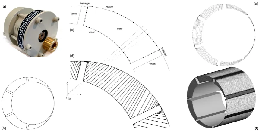
Starting from the ORC expander prototype shown in Figure 1.a and thanks to the symmetrical features of the vane machine geometry, the grid generation procedure was developed with reference to a 2D cross section of the rotating and deforming fluid domain and then replicated along the axial direction to get the 3D mesh. In particular, the reference fluid domain is the one enclosed between stator, rotor and blades (Figure 1.b). The developed grid generation methodology aimed at producing a computational grid that fulfilled the topology of an ‘O’ grid since this structure avoids any inaccuracies that can be introduced due to a non-matching mesh connection between core and leakage regions of the so-called rotor mesh.
Prior to the distribution of the computational nodes, the grid boundary is reconstructed through analytical relationships that describe the trajectories of rotor, stator and blades points. This approach provides flexible and parametric features to the overall procedure since it easily allows to model any vane machine geometry. For the current case, some geometrical data of the expander that have been used to generate the rotor boundary are listed in Table 1.
Fig. 1. Grid generation procedure: (a) prototype, (b) boundary generation, (c) boundary discretization, (d) stretching function applied to stator, (e) internal node distribution, (f) 3D grid
Figure 1.e shows the hexahedral cells in a 2D cross-section, whereas the continuous mesh between the tip leakage gaps and the core cells formed between the vanes allows that the number of cells covering the radial direction from the rotor boundary to the stator one remain unchanged. A refined boundary layer could have been introduced; however, in addition to the greater total mesh count, these cells would have further increased the cell aspect ratio in the tip gaps which are already stretched. Furthermore, a previous study on a dry air twin-screw expander showed that, with ANSYS CFX as solver and relying on the wall functions used by the k-ω SST turbulence model, the influence of adding boundary layer mesh is negligible for the prediction of the machine performance [22]. For these reasons, boundary layer refinement is not considered in this analysis. On the other hand, a key parameter for the grid generation is the minimum tip clearance gap, which is assumed to be constant at each angular location of the blade. In this work, three different values have been considered, namely 10, 20 and 50 µm.
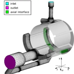
Full hexahedral 3D grid is displayed in Figure 1.f. Besides, Figure 2 represents the tetrahedral mesh used for the static ports of the real gas ORC expander. High pressure inlet, low pressure outlet and the axial interface of low pressure port with the deforming rotor domain have been highlighted by the color scheme. Radial interface of the high pressure port with the rotor is not seen. All these interfaces have been defined in the ANSYS CFX solver as non-conformal conservative flux type of fluid-fluid interfaces. Table 2 summarizes the specifics of rotor and ports grids while Table 3 presents the details of the CFD solver numerical setup. The operating conditions that were considered as benchmark for this case were 1551 RPM as revolution speed and 12.11 bara as inlet pressure with 90.5 °C as inlet
gas temperature. Outlet pressure was 4.57 bara.
Aungier Redlich Kwong real gas model was used to specify the coefficients of the polynomials to define material properties and equation of state. Coefficients for specific heat and critical state temperature and pressure were supplied to generate a lookup table in the temperature range of 273 and 400 K, while the pressure range was between 2.0 and 60.0 bara. The formulation for the specific heat at reference state (1.013bara, 25°C)
c
0p used by CFX is reported inEqn. 1. Coefficients are valid for R236fa only. Temperature is expressed in Kelvin while the units of the specific gas constant R are the same as
c
0p ones (J/kgK). Values for thermophysical properties at the critical point can be easily deduced from the literature or well-known fluid property databases.2 4
0 3
9.3568 0.013304
0.00021207
4.6189
07
3.7799
10
p4 Giuseppe Bianchi et al. / Energy Procedia 00 (2017) 000–000
Table 1. Summary of geometrical specifics.
[image:5.544.44.269.174.243.2]Rotor Diameter 65 mm Stator Diameter 76 mm Axial Length 60 mm Tip Clearance 10/20/50 µm
Table 2. Summary of mesh specifics.
Ports Rotor (10µm) Cell type Tetrahedral hexahedral Node count (Million) 0.135 0.157 Maximum aspect ratio 23 228
[image:5.544.49.502.271.437.2]Minimum orthogonality 10.0 11.6 Fig. 2. Ports mesh and sliding interfaces with the rotor grid
Table 3. Details on the numerical setups in the ANSYS CFX solver.
Mesh deformation User defined nodal displacement via junction box routines in FORTRAN
Advection scheme Upwind
Mesh in ports Tetrahedral with boundary layer refinements (Generated by ANSYS pre-processor)
Pressure-Velocity coupling Co-located layout (Rhie and Chow 4th order)
Turbulence model SST – k Omega (Standard Wall Functions)
Transient scheme Second order
(Fully implicit Backward Euler) Inlet boundary
condition
Opening (Specified total pressure and temperature)
Transient inner loop
coefficients Up to 20 iterations per time step
Outlet boundary condition
Opening (Static pressure
In case of backflow used as total pressure and temperature)
Convergence criteria r.m.s residual level 1e-03
Control volume
gradients Gauss divergence theorem
Relaxation parameters Solver relaxation fluids (0.4)
Time step size resulted from the ratio between the angular spacing at which the customized grids are available and the revolution speed. In this case study, the full rotation of the rotor was defined by 720 grid positions. This resulted in an angular step of 0.5° per solver step. Hence, to achieve a rotational speed of 1551 RPM, the time step size was set to 5.3728e-5 s. In these conditions, the RMS Courant number of the coupled solver during the calculations was in a range between 7.0 and 8.0 while the maximum Courant number was in the order of 110.0 at all time steps.
3.Results and discussion
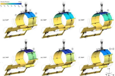
Fig. 3. Absolute gauge pressure field at rotor and discharge domains with superimposition of non-dimensional velocity vectors over a full vane rotation
the blades regardless of their angular position, is presented with respect to indicating pressure data from a previous experimental campaign.
3.1.Flow topology
Figure 3 shows the pressure field over a full revolution of the vane, whose duration is 51.4°. In particular, the angular positions refer to the last 50° of the 11th simulated revolution. Minimum tip clearance gap is 10 µm. In Figure
3, the non-dimensional velocity field at mid-length is superimposed to the pressure fields in the rotor and exhaust domains. Revolution speed sense is clockwise, as shown at the bottom right of the figure.
In Figure 3.a, the intake process takes place through the vertical branch of the inlet duct. Flow direction is from top to bottom. On the other hand, the horizontal branch does not have any flow inlet port and behaves as a stagnation zone. A recirculation can also be noticed near the outlet port, where the different outlet flows from the axial interfaces merge from former flow directions at 90°.
The first vane, i.e. the one marked with label “1” in Figure 3, at 310° is in the middle of the intake process and has pressure and temperature values imposed by the inlet boundary condition. Moving from subfigure (a) to (f), vane 1 completes the intake process and, in frame (f), is at angular position that corresponds to the beginning of the closed volume expansion. From (a) to (c), pressure in vane 1 decreases due to the slight increase of the chamber volume. However, when the second blade of cell 1 faces the intake duct at 340°, this partial obstruction of the duct leads to a pressure increase. In the last 20°, the chamber volume keeps increasing and lowers the fluid pressure of about 1.5 bar compared to the initial position (a). Therefore, the sequence shown in Figure 3 explains the reason of the not isobaric nature of the intake process in vane expander, in contrast with what occurs in compressors.
6 Giuseppe Bianchi et al. / Energy Procedia 00 (2017) 000–000
Furthermore, the pressure differences that occur between vane 1 and 2 lead to leakages that are clearly visible at 330° and 340°. Indeed, with reference to the tip clearance region, a remarkable pressure decrease can be noticed at the central region of the tip, which behaves as the throat of the nozzle created by blade and stator surfaces. Even though, the peripheral speed and pressure difference involved in the leakage are able choke the flow at the throat, the divergent section of the nozzle downstream the throat contributes to the pressure recovery. Further details are given in Section 3.2 and Figure 4.
3.2.Tip leakage flows
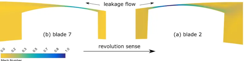
[image:7.544.78.474.283.383.2]Figure 4 details the flow regime at two main tip clearance locations. The reference position for this magnified view is 310°, i.e. Figure 3.a. Therefore, Figure 4.a shows the leakage that occurs between vane 1 (at intake pressure) and vane 2 (at the beginning at the closed volume expansion phase) while Figure 4.b is related to the flow between vane 6 and 7. In this particular location, blade 2 and 7 are symmetrical with respect to blade 1. However, even though the nozzles shape is the same, the flow fields differ because of pressure differences across the blades and leakage flow direction. Indeed, in Figure 4.a the leakage flow is aligned with the revolution sense while in Figure 4.b the leakage is opposite to it. In Figure 4.a the tip clearance gap gets chocked at the nozzle throat which is located in the first half of the blade tip profile. A similar situation occurs in blades 3 and 4 that are not shown.
Fig. 4. Mach number field at main tip clearance locations: (a) between chambers 1 and 2, (b) between chambers 6 and 7. Reference position is Figure 3.a at mid axial length while minimum gap width is 10µm
3.3.Comparison with indicating pressure data
The developed grid generation methodology assumes a fixed minimum clearance at the gaps between stator and blades tips. The input value specified by the user during the simulation setup not only has an impact of the overall rotor mesh quality but also on the simulation results. In fact, there is a direct relationship between minimum clearance and leakages. In real operating conditions, this value has an angular variation that depends on the peripheral tip speed, the pressure difference across blade as well as the hydrodynamic capabilities of the working fluid [10, 24].
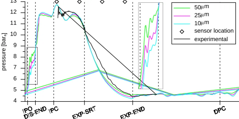
In order to assess the impact of minimum tip clearance gap on the overall angular evolution of the chamber pressure, simulations with values of 50µm, 25µm, 10µm were compared to experimental indicating pressure data. The experimental pressure trace was reconstructed through a phase-locked average of the raw data provided by four piezoelectric sensors shown in Figure 5 as diamonds. Further details can be found in [7, 23].
The effects of different tip gaps are highly noticeable in multiple angular ranges. Let us firstly refer to the angular phase where the vane is exposed both to intake and discharge ports and lasts from the Intake Port Opening (IPO) to the Discharge End (DIS-END). In this phase, pressure would normally increase due to the decrease of chamber volume, as shown for cell 7 in Figure 3. However, the larger the tip clearance, the steeper is this pressure increase since the throttling action of the nozzle generated by blade tip and stator is more limited.
During the closed volume expansion, which starts at EXP-SRT and ends at EXP-END in Figure 5, due to leakages the high pressure mass that is trapped at the end of the intake process gradually tends to move towards lower pressure environments. In turn, even though the three simulations have the same built-in volume ratio, in the 10µm one the expansion is more effective and slightly goes below the discharge pressure before approaching the opening of the discharge port. On the other hand, in the simulation cases with larger tip gaps, the over-expansion gradually vanishes.
Fig. 5. Effect of minimum tip clearance on simulated vane pressure trend and comparison with experimental data
Although the numerical data are in good agreement with respect to the experimental pressure trace, some deviations can be certainly noticed. Some of the explanations for these discrepancies are the approximations on the grid generation methodology and for having discarded the leakage paths that take place between the chambers and the end wall clearances. In fact, if larger leakage flows occurred due to the additional paths, with reference to the trends shown in Figure 5, one could expect a better matching with the experimental data, without necessarily considering unrealistic tip gaps. Besides, the numerical approach did not considered any heat transfer. Nonetheless, the sensible and convective heat transfers to the environment are expected to be minimal due to the limited temperature differences between the fluid and the operating ambient conditions during the tests. Moreover, the occurrence of such heat loss would actually bring the pressure trace below the adiabatic one, and not opposite to it as in the experiments.
4.Conclusions
The moving and deforming features of computational fluid domains were the major obstacle to the application of the numerical simulation for the development of next generation sliding vane machines. The research presented in this paper tackled and addressed this challenge through the development of a grid generation methodology that is based on user defined nodal displacement and it is able to successfully discretize the cell fluid domains. The developed approach is detailed and parametric in representing the vane machine geometry. Furthermore, the generated grids can be coupled with most of the available commercial and open source CFD solvers.
Using the customized set of grids, single phase transient three-dimensional CFD simulations in ANSYS CFX were carried out with reference to a small scale ORC expander. The numerical analysis provided remarkable information on the overall flow topology and the tip leakage flows. The effect of minimum tip clearance gap, which is an input to the grid generation methodology and whose dependency with the angular position has been so far neglected, was further investigated through different simulation cases and compared with experimental indicating pressure data.
The agreement between numerical and experimental data is fairly satisfactory. However, a more accurate validation would require the inclusion of end wall leakage fluid domains as well as an angular variation of the minimum gap between blade tip and stator.
4 5 6 7 8 9 10 11 12 13
pressure [bar
a
]
50µm 25µm 10µm
8 Giuseppe Bianchi et al. / Energy Procedia 00 (2017) 000–000
Nevertheless, the numerical methodology herein developed is potentially applicable to any sliding vane machine such as air and refrigeration compressors as well as oil and water pumps for automotive applications.
Acknowledgements
The work documented in this report has been funded by the 2015 Scholarship of the Knowledge Center on Organic Rankine Cycle technology (www.kcorc.org), the organization formed by the members of the ORC Power Systems committee of the ASME International Gas Turbine Institute (IGTI).
References
[1] D. Vittorini and R. Cipollone, Energy saving potential in existing industrial compressors, Energy, Volume 102, 1 May 2016, Pages 502-515, ISSN 0360-5442, DOI: 10.1016/j.energy.2016.02.115.
[2] D. Wang et al., Numerical Modeling of Vane Oil Pump with Variable Displacement, SAE Technical Paper 2012-01-0637, 2012, DOI: 10.4271/2012-01-0637.
[3] R. Cipollone and D. Di Battista, Sliding vane rotary pump in engine cooling system for automotive sector, Applied Thermal Engineering, Volume 76, 5 February 2015, Pages 157-166, ISSN 1359-4311, DOI: 10.1016/j.applthermaleng.2014.11.001.
[4] J. F. Tang et al. Theoretical study of a novel Sliding-Vane Rotary Pump–structure analysis and its chamber pressure, Particulate Science and Technology (2016): 1-11. DOI: 10.1080/02726351.2016.1211777
[5] B. Yang et al., Experimental investigation on the internal working process of a CO2 rotary vane expander, Applied Thermal Engineering, Volume 29, Issues 11–12, August 2009, Pages 2289-2296, ISSN 1359-4311, DOI: 10.1016/j.applthermaleng.2008.11.023.
[6] R. Cipollone et al., Mechanical Energy Recovery from Low Grade Thermal Energy Sources, Proceedings of the 68th Conference of the Italian Thermal Machines Engineering Association, Energy Procedia, Volume 45, 2014, Pages 121-130, ISSN 1876-6102, DOI: 10.1016/j.egypro.2014.01.014
[7] G. Bianchi and R. Cipollone, Friction power modeling and measurements in sliding vane rotary compressors, Applied Thermal Engineering, Volume 84, 5 June 2015, Pages 276-285, ISSN 1359-4311, DOI: 10.1016/j.applthermaleng.2015.01.080
[8] Y. M. Huang and S. Yang, A measurement method for air pressures in compressor vane segments, Measurement, Volume 41, Issue 8, October 2008, Pages 835-841, ISSN 0263-2241, DOI: 10.1016/j.measurement.2005.11.027.
[9] O. Al-Hawaj, Theoretical modeling of sliding vane compressor with leakage, International Journal of Refrigeration, Volume 32, Issue 7, November 2009, Pages 1555-1562, ISSN 0140-7007, DOI: 10.1016/j.ijrefrig.2009.07.005.
[10] G. Bianchi and R. Cipollone, Theoretical modeling and experimental investigations for the improvement of the mechanical efficiency in sliding vane rotary compressors, Applied Energy, Volume 142, 15 March 2015, Pages 95-107, ISSN 0306-2619, DOI: 10.1016/j.apenergy.2014.12.055 [11] O. Badr et al., Multi-vane expanders: Vane dynamics and friction losses, Applied Energy, Volume 20, Issue 4, 1985, Pages 253-285, ISSN
0306-2619, DOI:10.1016/0306-2619(85)90018-2.
[12] A. B. Tramschek and M. H. Mkumbwa. Mathematical modelling of radial and non-radial rotary sliding vane compressors, International Compressor Engineering Conference at Purdue University, 1996, West-Lafayette (IN), United States, URL: docs.lib.purdue.edu/icec/1151/ [13] Simerics PumpLinx, URL: www.simerics.com/pumplinx
[14] ANSYS CFX, URL: www.ansys.com/products/Fluids/ANSYS-CFX
[15] G. Montenegro et al., Evaluating the Performance of a Rotary Vane Expander for Small Scale Organic Rankine Cycles Using CFD tools, Energy Procedia, Volume 45, 2014, Pages 1136-1145, ISSN 1876-6102, DOI:10.1016/j.egypro.2014.01.119.
[16] G.Montenegro et al., CFD Simulation of a Sliding Vane Expander Operating Inside a Small Scale ORC for Low Temperature Waste Heat Recovery, SAE Technical Paper 2014-01-0645, 2014, DOI:10.4271/2014-01-0645.
[17] P. Kolasiński and P. Błasiak, Experimental and Numerical Analyses on the Rotary Vane Expander Operating Conditions in a Micro Organic Rankine Cycle System, Energies, Volume 9, 2016, ISSN 1996-1073, DOI: 10.3390/en9080606.
[18] G. Bianchi et al., Development of a general numerical methodology for CFD analyses in sliding vane machines and application on a mid-size oil injected air compressor, in: Proceedings of the International Compressor Engineering Conference, Purdue University, 2016 URL: docs.lib.purdue.edu/icec/2454/
[19] S. Rane, A. Kovacevic, N. Stosic, & M. Kethidi, (2013), Grid deformation strategies for CFD analysis of screw compressors, International Journal of Refrigeration, Volume 36, Issue 7, Pages 1883-1893, ISSN 0140-7007, DOI: 1016/j.ijrefrig.2013.04.008.
[20] A. Kovacevic and N. Stosic and I. Smith, Screw Compressors - Three Dimensional Computational Fluid Dynamics and Solid Fluid Interaction, Springer, 2006, ISBN: 978-3-540-36302-6
[21] Kovačević A., 2005. Boundary Adaptation in Grid Generation for CFD Analysis of Screw Compressors, Int. J. Numer. Methods Eng., Vol. 64: 401-426.
[22] S. Rane, Grid Generation and CFD analysis of Variable Geometry Screw Machines, 2015, PhD Thesis, City University London, URL: openaccess.city.ac.uk/id/eprint/15129.
[23] G. Bianchi, Exhaust Waste Heat Recovery in Internal Combustion Engines - Development of an ORC-based power unit using Sliding Vane Rotary Machines, 2015, ISBN 978-88-87182-69-9, DOI: 10.13140/RG.2.1.4095.7282