Design and development of magnetic resonance imaging (MRI) compatible tissue mimicking phantoms for evaluating focused ultrasound thermal protocols
Full text
Figure

![Table 1-4: Acoustic attenuation coefficient for different Biological Tissues [16], [17]](https://thumb-us.123doks.com/thumbv2/123dok_us/1420391.94778/25.595.111.541.250.600/table-acoustic-attenuation-coefficient-different-biological-tissues.webp)
![Figure 1.2: Arrhenius plots for different cell lines of humans and rodents [11].](https://thumb-us.123doks.com/thumbv2/123dok_us/1420391.94778/28.595.204.452.54.274/figure-arrhenius-plots-different-cell-lines-humans-rodents.webp)

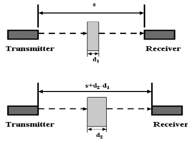
![Figure 3.2: Single transducer pulse echo method [10].](https://thumb-us.123doks.com/thumbv2/123dok_us/1420391.94778/60.595.116.530.512.743/figure-single-transducer-pulse-echo-method.webp)
Outline
Related documents
The researcher also suggests that further research be carried out in Kenya, in the following areas : Factors that influence student interest in learning languages, teacher affect
To assess a teacher’s attributions, the researchers employed the English Language Teacher Attribution Scale (TAS), which was designed and validated by Ghanizadeh and
[43] evaluated photocatalytic activity of mesoporous titania supported nickel oxide photocatalyst synthesized by single – step sol-gel (SSSG) process combined with
In both – football business income structure and football business expenditure structure – some elements are related with the individual football club (e.g. investment to
The experimental data is shown as solid diamonds, the ideal gas is shown as solid circles and the open symbols show the calculations with variations of different constraints on
(2) Subject to paragraph (4), United States tax paid under the law of the United States and in accordance with this Convention, other than United States tax imposed in accordance
Twenty-two states already require genetic and other available medical information from biological parents to predict the health risks of the child.. As direct DNA
In the past, early spinal fusion was performed in children with severe progressive EOS, which corrected scoliosis but limited spine and thoracic growth and resulted in poor
