Different Methods for Predicting and Optimizing
Weld Bead Geometry with Mathematical Modeling
and ANN Technique
Jigesh Yadav, Manikant Paswan
Abstract Bead geometry plays very important role in predicting the quality of weld as cooling rate of the weld depends on the height and bead width, also bead geometry determines it’s residual stresses and distortion. Weld bead geometries are outcomes of several welding parameters taken into consideration. If arc travel is high and arc power is kept low it will produce very low fusion. If electrode feed rate is kept higher width is also found to be on higher side which makes bead tto flat. Also, the parameters like current, voltage, arc travel rate, polarity affects weld bead geometry. Hence, this paper is a review of different experimentations and modeling techniques regarding predictions of weld bead geometry and their relations with different weld parameters.
Contents
1. Introduction (1)
2. Experiments Performed (2)
3. Different Modeling Techniques (6) 3.1 Artificial neural network (6)
3.2 Mathematical modeling (Linear Regression) (7) 3.3 Mathematical Modeling (Curvilinear regression)
(7)
4. Results and Conclusions (8)
5. Future Scope (8)
6. References (8)
I. INTRODUCTION
Weldability of material are determined by various factors such as bead geometry, thermal cracks, undercutting, heat affected zone (HAZ) and penetration. These factors are influenced by various parameters like electrode’s nature, length of arc, rate of deposition of metal, rate of arc travel and polarity.
Length of arc is an important feature as long arc spreads to larger area and increases bead width. Also too short and too large arc results in poor penetration [1,2]. Electrode coating plays an important role in determining nature of weldament which is reflected in properties of joins such as hardness and load bearing capacity. Penetration and dilution are dependent on deposition rate and rate of arc travel. If rate of travelling of arc is increased width is decreased whereas undercutting increases.
Heat affected zones, penetration and bead geometry changes with any change in heat input in polarity. Heat distribution is more in anode than in cathode [4,5,6,7]. Graham [4] believes that approx. 2/3rd generation of energy occurs at anode and 1/3rd occurs at cathode.
Revised Manuscript Received on August 05, 2019.
Jigesh Yadav, Assistant Professor (Mechanical Engineering Department) at MIT Muzaffarpur, Research Scholar, (Mechanical Engineering Department) at NIT Jamshedpur.
Manikant Paswan, Professor (Mechanical Engineering Department) at NIT Jamshedpur.
Apps[9] also came to same conclusions that welding parameters like polarity, welding speed current and voltage influences bead geometry. Gurev and stout [10] performed experiments on MIG welding and concluded that bead width increases with increased heat input and decreased arc travel rate or increased current.
Christensen et. Al. [11] found out that weld bead geometry was related to effective heat input to the plate. Heat input to the plate was obtained from arc travel rate, arc current and arc voltage. Begem et. Al. [12] observed that bead width and height are larger when polarity is reversed and bead width is directly proportional to energy supplied. Begman et al [12] observed that bead width and height are larger when polarity is reversed and bead width is directly proportional to energy supplied.
Modeling and optimization for weald bead geometry are done by methods like response surface methodology, Taguchi Method and Regression analysis in GMAW [13-16]. Palani and Murugun [17] introduced mathematical model for predicting weld bead structure in FCAW using response surface methodology. S Pal and YS Tarng [18,19] analyzed the effect of various parameters on weld bead geometry through Taguchi method. N Karunakaran [20] read effects of pulse current on weld bead profiles. Sensitivity analysis was used for prediction of weld bead geometry [22-25].
Some work has also been done for increasing deposition on conventional GMAW. Tandem GMAW [26] and variable polarity GMAW [27] are some of the advancements made for increasing deposition rates. Other approaches for this purpose are using twin arc mode [28,29] and adding metal powder [30-32].
Rate of cooling of a weld can be determined by bead height and bead width. Bead cross sectional area, height, width, penetration, reinforcements etc. determine its residual stresses and distortion. Hence, it can be clearly seen welding parameters effects bead geometry, penetration, cracks, Heat affected zone and hardness. In this paper different approaches and modeling techniques would be discussed that has been used in the past for analyzing and predicting weld bead geometry with respect to given condition.
II. EXPERIMENTS PERFORMED
Ganesh and Dutta [21] performed an experiment. His aim was to see the results when grey cast Iron is welded with Mild steel electrodes. Constant power source was maintained with variations in feed rates, parameters used were arc length and arc travel rate. Variation in arc power was achieved by varying the
were used. Around 15 cm of the bead were deposited before keeping it in open atmosphere and no heat treatment was given after welding. After these beads were polished and were etched with 2% metal solution. Bead height and width were then measured and their average values were computed. An epidiascope was used for amplifying the images of penetration and heat affected zone. With the help of these images penetration area and depth were estimated and were compared with Tool Maker’s Microscope’s measurements. The comparisons were significantly in agreement.
[image:2.595.75.264.188.326.2]Fig.1 Macro-photograph showing proper fusion between mild steel and grey cast Iron.
Fig. 2. Macro-showing poor fusion between the mild steel and grey cast iron .
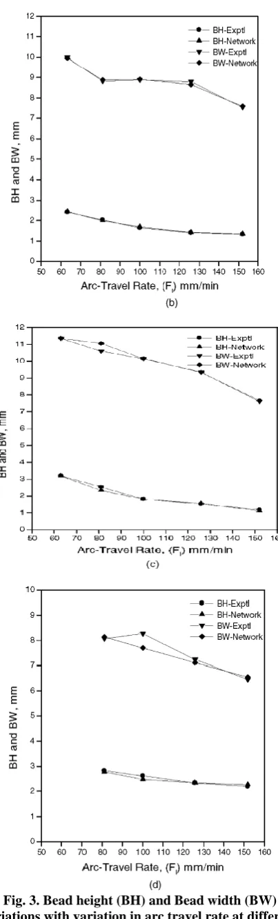
Fig. 3. Bead height (BH) and Bead width (BW) variations with variation in arc travel rate at different
[image:2.595.83.254.544.743.2]Yong-hua SHI [33] performed experiment of underwater wet flux cored arc welding (FCAW). A hyperbaric chamber was used with automatic welding system inside it. Figure 4 shows the schematic diagram of experimental setup. The system consists of a high pressure underwater welding chamber, a welding power source, a three-dimensional motion platform and other equipments. Firstly the water was squeezed inside the chamber until water level is .1 m above work piece. For simulating the pressure caused due to depth of water compressed air was used. A flux cored self-shielded wire was used to deposit beads on Q 235 steel plates. He found that the parameters which wear affecting bead geometry were current, arc travel rate, voltage tube to work distance and water depth. Since no other parameters effect bead geometry that significantly [34,35−37] therefore, no other interactions were considered during this experiment. Relationship between bead geometry and parameters were studied with the help of L16(45) orthogonal array. The weld beads formed during this experiment are shown in Fig. 5. For measuring bead width, reinforcement and penetration shown in Fig. 6, each one of them were divided into three parts i.e., left, middle and right and their average values were calculated.
[image:3.595.75.267.339.482.2]Fig. 4 Schematic diagram of underwater flux cored arc welding.
Fig. 5 Weld bead: (a) low water level (b) At 40 m depth
Fig. 6 (a) Weld bead cross section (b) Weld bead geometry
R
. A. Riebero [39] used cold wire gas metal arc welding. He used CW-GMAW process for his experiment. In this process instead of using an electrode wire, a non-electrode wire is melted and deposited on base metal by putting in electric arc region. According to Ref. 40, the main advantage of this process is that along with all the advantages of conventional GMAW it has got a cool weld pool also weld bead quality is very good and deposition rates are high too. CW-GMAW process is shown in Fig. 7. The parameters used in this type of welding are weld speed, gas flowing rate, tip to work piece distance along with voltage and feed rate of wire. Parameters taken into consideration are electrode and non-electrode feed rate ratio along with arc current. The cold wire feed rate ratio is taken in (%) and defined as follows:
Where Ws represents cold wire feed rate and E represents electrode feed rate.
Fig. 7. General Scheme for CW GMAW
Voltage was kept constant i.e., 37 volts, electrode feed rate were varied between 10, 12
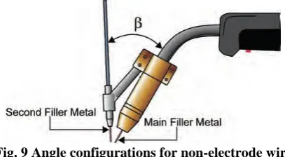
[image:3.595.85.232.530.617.2] [image:3.595.317.542.539.714.2]whereas, current was taken as 300, 340 and 380 Amperes as shown in Figure 8. Gun and tip angle was maintained at 61o whereas work angle and attack angle was kept 900 as shown in Fig. 9. Output variables were calculated with the help of transverse cross sections by using a Power map BS- 912B hacksaw. After etching and polishing the cross section with 6% Nital height, width, dilution and penetration were measured. Dilution is very important parameter in determining quality of weld as excessive dilution will lead to chemical changes in deposited metal which will in turn bring its mechanical behavior changes.
[image:4.595.52.287.188.284.2]Fig. 8 Fluxogram of parameters used in the experiment.
Fig. 9 Angle configurations for non-electrode wire feeding system for CW-GMAW.
V Gunraj [38] used response surface methodology for predicting bead geometry. Material chosen was I.S.2062 carbon steel having dimensions 300 X 150 X 6 mm. Coil wire used was ESAB SAI coated with copper having diameter 3,15 mm and ESAB G.S. 0.2-1.16 was used as flux. A reflective profile projector was used for drawing bead profile and digital palnimeter was used for measuring values of parameters.
L. J. Yang [42] and N. Murugan [41] studied effects of process variables on bead width of submerged arc welding. He used 19 mm thick ASTM A36 steel plate as base metal. 600x150 mm work piece was sand blasted for cleaner surface and to make sure no oxides are present. Electrode material used was Lincon L60 and fluxed used was fused Linde 124 which was acidic in nature and OP121TT which was basic in nature. Electrode diameter was taken in between 2.5, 3.3 and 4.1 mm. Power supply used was Miller 1500 DC. It could be used either as constant voltage or constant current source. Both negative and positive polarity was used. With preselected electrode extension, polarity, welding speed and electrode diameter different values of arc voltage and welding current were noted. Electrode extension is the distance between the bottoms of the electrical contact collar around the electrode to top surface of the work-piece. Ravinder Pal Singh [43] selected open circuit voltage, wire feed rate, contact tip to work distance and travel speed as operating parameters. He varied one of the parameters keeping other parameters constant. Parameter values were
decided on the basis of smooth operation and smooth weldaments without any defect.
[image:4.595.66.270.312.424.2]B. Sethil Kumar [44] used flux cored arc welding process on super duplex cladding of stainless steel. Experimental setup is shown in Figure 10. Welding machine used was Lincoln electric PRO V 350 and it was coupled with wire feeder LF 74. The electrode used in this set up was Metrode Supercore FC 2507 (AWS A5.22E2594T0-4). Low carbon steel was used as base metal. A 80/20 % Argon/carbon di oxide is used as shielding gas material with a flow rate of 25 L/min.
Fig. 10. Experimental Setup 1. Different Modeling Techniques 3.1 Artificial Neural Networks
Artificial Neural Network is very effective tool in generating new unseen data with the help of obtained or known data. In our case if we can use values of parameters which are obtained through experimentations and output data which are seen i.e., bead width, height, reinforcements, penetration etc. and program it to get no. of more data, hence we won’t be needing too many experiments to get all the required data. By getting an optimum amount of data from this neural network we can create a table with various values of input parameters along with their output values. In this way we can easily predict characteristics and quality of weld bead produced without requirement of performing actual experimentation.
3.2 Mathematical modeling (Linear Regression)
Output variables are shown as second order equations as shown below.
Output variable Y = f (X1 , X2 ,X3 ,X 4 ,X5,) ……(1)
Where
Y – Output variable X1 – Wire feed rate X2 – Welding gun angle X3 – Nozzle to plate distance X4 – Welding voltage X5 – Welding speed
Equation of second order representing the output as a function of parameters is shown in equation. 2.
……… (2)
The above Equation of second order can be expressed with all coefficients and parameters as shown in equation 3.
Y=
13 1 3+ 14 1 4+ 15 1 5+ 23 2 3+ 24 2 4+
25 2 5+ 34 3 4+ 35 3 5+ 45 4 5……
………. (3)
If we have 21 input parameter values and correspondingly 21 outputs we can make 21 equations with 21 unknown constants by putting the values in above equations. Thus, the values of constant can be
equation can be formed. Thus it becomes very simple to predict weld bead geometry by just putting the values of parameters in that equation
.
3.3 Mathematical Modeling (Curvilinear regression) As explained above in place of linear regression we can use curvilinear regression i.e. an equation in exponential form giving relation between input variables and output variables as shown in Equations. (4) − (6). This will make the work further easier as there will be less no. of constants to be calculated for making a general equation.
………
(4)
……….(5)
……..……(6)
Where,
A – Welding current V- Arc voltage U – Travel speed
S – Contact tube to work distance D – Water Depth
fR( ), fW( ) and fP( ) are
reinforcement, bead width and penetration and function at given conditions respectively. b0, b1, b2, b3, b4, b5,
c0, c1, c2, c3, c4, c5, d0, d1, d2, d3, d4 and d5 are curvilinear constants which could be found out by using any mathematical tool like Matlab and a general equation can be formed.. These equation can further be simplified in the form as shown in equation 7,8 and 9 .
ln fW( ) = b0 + b1 ln aA+ b2 lnV+ b3 ln U+b4 ln
S + b5 lnD………. (7)
ln fP ( ) = c0 + c1 ln A + c2 lnV + c3 ln U + c4 ln S
+ c5 ln D ………(8)
ln fR ( ) = d0 + d1 ln A + d2 lnV + d3 ln U + d4 ln S + d5 ln D ………...(9)
III. RESULTS AND CONCLUSIONS
1
. Fusion was found out to be very poor while depositing mild steel on grey cast Iron irrespective of high arc travel or very small arc power. This could be overcome by preheating the plate keeping arc travel rate very low and arc power high.2. If arc travel rate is increased bead height and width decreases but decrease in height is more as compared to decrease in width.
3. If electrode feed rate is raised with increase in arc power keeping constant arc length there is no significant effect on bead height but bead width increases.
4. If electrode feed rate is kept constant thereby increasing arc length bead width decreases and height increases. 5. Increasing arc power to increase arc length from short to medium results in rapid increase of area and penetration depth.
6. For proper penetration and efficient heat utilization it is necessary to use optimum arc length i.e. it should neither be very small nor too long.
7. By keeping arc length constant and increasing electrode feet rate heat affected zone and penetration was increased.
8. By using high current, straight polarity, smaller electrode diameter and long electrode extension melting rate of Submerged Arc welding can be increased.
9. If electrode diameter is kept low, any changes in current level won’t affect bead height width or penetration but fast wire speed which increases melting rate may hamper automatic arc length control.
10. Bead height and width increases if longer electrode extensions are used and current is kept low, but this increase in bead height and width are not significantly affected with increase in current. However, over heating of long electrode extension may cause some practical problems.
11. Weld bead geometry is significantly affected by polarity. 12. Weld bead geometry i.e. bead height, width, penetration etc. are on higher side when DCEP polarity is used instead of DCEN polarity, only the reinforcement is exception.
IV. FUTURE SCOPE
Various researches can be further carried out to understand effects of welding parameters and weld bead geometry on various microscopic properties of weld bead such as hardness, strength, residual stresses etc. Weld bead geometry can further be optimized on the basis of these microscopic properties. Weld bead geometry can also be predicted by applying response surface methodology and Taguchi Method.
REFERENCES
1. J.B. Austin, Electric Arc Welding, Am. Tech. Soc., Chicago, 1956.
2. T.B. Jefferson, The Welding Encyclopedia, McGraw-Hill, New York,
1951.
3. P.I. Houldcroft, Welding Process, Cambridge University Press,
Cambridge, 1967.
4. F.D. Graham, Audels Welder Guide, Taraporevala Sons and Co.,
Bombay, 1966.
5. B. Ronay, The significance of extremity in curve welding, Weld.
Architect (1960)
6. B.E. Rossi, Welding and its Applications, McGraw-Hill, New York,
1941.
7. V. Tsegelsky, The Electric Welder, Foreign Language Publishing
House, Moscow, 1976.
8. Shumovsky A, Controlling welding shrinkage and contortion, The
Canadian Welder, April, 1952.
9. R.L. Applications, L.M. Gourd, K.A. Lelson, Effect of welding
factors upon globule shape and size in submerged-circular segment welding, Weld. Met. Fabr. (1963).
10. H.S. Gurev, R.D. Strong, Solidification marvels in dormant gas
metalarc welds, Weld. J. (1963)
11. N. Christensen, V.L. de Davies, K. Gjermurdsen, Distribution of
temperatures in curve welding, Brit. Weld. J. (1965)
12. M.L. Begeman, B.H. Amstead, U.I. Mashruwala, Effects of decreased
climatic weight on circular segment welding attributes, Weld. J. (1950)
13. PAL K, PAL S K. Delicate processing strategies utilized for the
displaying and improvement of gas metal curve welding: A survey [J]. Universal Journal of Manufacturing Research, 2011.
14. MURUGAN N, PARMAR R S. Impacts of MIG process parameters
on the geometry of the dab in the programmed surfacing of tempered steel [J]. Diary of Materials Processing, 1994.
15. KIM I S, BASU A, SIORES E. Numerical models for control of weld
dot infiltration in the GMAW procedure [J]. Universal Journal of Advanced Manufacturing Technology, 1996.
16. RAO P S, GUPTA O P, MURTY S N, RAO A B K. Impact of
17. PALANI P K, MURUGAN N. Advancement of scientific models for expectation of weld dab geometry in cladding by transition cored curve welding J. Worldwide Journal of Advanced Manufacturing Technology, 2006.
18. PAL S, MALVIYA S K, PAL S K, SAMANTARAY A K.
Improvement of value qualities parameters in a beat metal inactive gas welding procedure utilizing dim based Taguchi technique J. Worldwide Journal of Advanced Manufacturing Technology, 2009.
19. TARNG Y S, YANG W H. Advancement of the weld dot geometry in
gas tungsten bend welding by the Taguchi technique J. Global Journal of Advanced Manufacturing Technology, 1998.
20. KARUNAKARAN N, BALASUBRAMANIAN V. Impact of beat
current on temperature conveyance, weld dot profiles and qualities of gas tungsten bend welded aluminum combination joints J. Exchanges of Nonferrous Metals Society of China, 2011
21. NAGESH D S, DATTA G L. Hereditary calculation for advancement
of welding factors for stature to width proportion and utilization of ANN for forecast of dot geometry for TIG welding process J. Connected Soft Computing.
22. KIM I S, JEONG Y J, SON I J, KIM I J, KIM J Y, KIM I K,
YARAGADA P K D V. Affectability examination for procedure parameters impacting weld quality in automated GMA welding process J. Diary of Materials Processing Technology, 2003.
23. PALANI P K, MURUGAN N. Affectability investigation for
procedure parameters in cladding of tempered steel by transition cored circular segment welding J. Diary of Manufacturing Processes, 2006.
24. KIM I S, SON K J, YANG Y S, YARAGADA P K D V. Affectability
investigation for procedure parameters in GMA welding procedures utilizing a factorial plan technique J. Universal Journal of Machine Tools and Manufacture, 2003.
25. KARAOGLU S, SECGIN A. Affectability examination of submerged
circular segment welding process parameters J. Diary of Materials Processing Technology, 2008.
26. Ueyama, T., Ohnawa, T., Tanaka, M., and Nakata, K. 2005. Impacts
of light setup and welding current on weld dab development in fast pair beat gas metal circular segment welding of steel sheets. Science and Technology of Welding and Joining .
27. Talkington, J. E. 1998. Variable extremity gas metal bend welding. Doctoral thesis, The Ohio State University.
28. J. E. Hinkel, F.W. Forthoeffel, High turmoil thickness submerged
circular segment welding with twin wires, welding J. (1976)
29. RS Chandel affidavit qualities of twin wire submerged circular
segment welding process, proc. Int. perplex seaward materials and ice building gathering, Houston, February, 1990
30. I I Ivochkin et al, prospect for the utilization of powdered filler metal
in combination welding, weld push. (1969)
31. W. Troyer, J. Mikurak, High testimony submerged curve welding
with iron powder joint fill. Welding J. (1974)
32. N Baily, Submerged curve welding ferritic steels with alloyed metal powder, welding J. (1991).
33. Yong-hua SHI, Ze-pei ZHENG, Jin HUANG, Sensitivity model for
expectation of globule geometry in submerged wet transition cored circular segment welding, Trans. Nonferrous Met. Soc. China 23(2013)
34. PALANI P K, MURUGAN N. Affectability examination for
procedure parameters in cladding of tempered steel by transition cored circular segment welding [J]. Diary of Manufacturing Processes, 2006.
35. KARAOGLU S, SECGIN A. Affectability examination of submerged
bend welding process parameters [J]. Diary of Materials Processing Technology, 2008.
36. KATHERASAN D, ELIAS J V, SATHIYA P, HAQ A N.
Reenactment and parameter streamlining of motion cored circular segment welding utilizing counterfeit neural system and molecule swarm enhancement calculation J. Diary of Intelligent Manufacturing, 2012.
37. SATHIYA P, ARAVINDAN S, JEYAPAUL R, AJITH P M, HAQ A
N. Advancing the weld globule qualities of overly austenitic treated steel (904L) through dark based Taguchi technique [J]. Multidiscipline Modeling in Materials and Structures, 2010.
38. V. Gunaraj , N. Murugan , Application of reaction surface system for
anticipating weld dot quality in submerged curve welding of channels, Journal of Materials Processing Technology (1999) .
39. R. A. RIBEIRO, E. B. F. SANTOS, P. D. C. ASSUNÇÃO, R. R.
MACIEL, AND E. M. BRAGA Predicting Weld Bead Geometry in the Novel CWGMAW Process.
40. Assuncão, P. D. C. 2013. Estudo da Viabilidade do Processo de
Soldagem GMAW-DCW (twofold virus wire). Ace theory. Belém, Paré, Brazil. Government University of Pará. In Portuguese.
41. N. Murugan, R.S. Parmar, Effect of SAW process factors on globule
geometry in single wire surfacing, J. Mater. Procedure. Technol. 37 (1993).
42. L. J. Yang, R.S. Chandel, M.J. Bibby, The impacts of procedure
factors on the dab width of submerged-curve weld stores Journal of Materials Processing Technology, 29 (1992)
43. Ravinder Pal Singh, R.K.Garg, Dinesh Kumar Shukla, Mathematical
displaying of impact of extremity on weld globule geometry in submerged curve welding, Journal of Manufacturing Processes.
44. B. Senthilkumar, T. Kannan, Effect of Flux Cored Arc Welding
process parameters on dab geometry in overly duplex tempered steel claddings
AUTHORSPROFILE
Jigesh Yadav – Has completed B.Tech from SSCET Bhilai INDIA, M.Tech. from National Institute of Technology Jamshedpur and persuing Ph.D. from
National Institute of Technology Jamshedpur.
Currently working as Assistant Professor in
Mechanical Engineering Department at Muzaffarpur Institute of Technology.
Mani Kant Paswan – Currently working as
Professor at National Institute of Technology
![Fig. 6 (a) Weld bead cross section (b) Weld bead geometry . A. Riebero [39] used cold wire gas metal arc welding](https://thumb-us.123doks.com/thumbv2/123dok_us/8185705.256265/3.595.85.232.530.617/weld-cross-section-weld-geometry-riebero-metal-welding.webp)