International Journal of Innovative Technology and Exploring Engineering (IJITEE) ISSN: 2278-3075,Volume-8 Issue-11, September 2019
An Automated Testing Method for PXI Chassis
Software Driver
Mohamad Khairi Ishak, Ng Wai Shyan, Mohamed Fauzi Packeer Mohamed
Abstract: PCI extensions for instrumentation (PXI) chassis is a
multi-vendor interoperable device. It can interconnect with many chassis, module and computers. To make sure a device driver is able to function in a specific configuration, it must go through a series of tests. The complexity of PXI software testing has increased when it needs to cover multiple configurations for a single driver. Majority of the automated test systems will execute tests without having the mechanism to verify the test environment. To improve the PXI chassis driver test duration, the current trend of automated software testing only executes a single test configuration. Thus, an automated test software with the capability to execute multi-test configuration is required. In order to develop this tool, a server-client concept is adopted. The advantage of server-client is to centralize the testing when multiple tests are performed. The software tool client will start once it is booted into the operating system; the test system will connect to server and wait for further action from server. When server detects incoming client connection, it will automatically verify and fix the testing environment; if the client fulfills the test suite requirement it will start to execute the test system. All client test summary results will be updated to the server. The results show an average of 17.1% test duration reduction on the planned test configuration when the automated software tool is applied on testing. Besides, the results indicate higher controller hardware performance can reduce the test duration.
Index Terms: About four key words or phrases in alphabetical
order, separated by commas.
I. INTRODUCTION
A hardware device which is plugged into a computer requires a software driver. To configure the device, the software driver tells the operating system to recognize the device properly. The device driver provides libraries of configuration parameter and kernel module during the operating system startup. The driver is not only limited in providing a correct configuration to the operating system, it also provides function, support application and help reference document for end user [1,2]. To produce and make sure a device driver is in this high-quality state, the software must go through a comprehensive testing phase. As part of driver package, test and measurement equipment driver is provided for user application programming and software application. This piece of software must support different platforms and hardware configurations. Because of the flexibility and complexity of the device driver, it is important Revised Manuscript Received on September2, 2019.
Mohamad Khairi Ishak, School of Electric and Electronic Engineering, Universiti Sains Malaysia, Nibong Tebal,14300, Pulau Pinang, Malaysia.
Ng Wai Shyan, School of Electric and Electronic Engineering, Universiti Sains Malaysia, Nibong Tebal,14300, Pulau Pinang, Malaysia.
Mohamed Fauzi Packeer Mohamed, School of Electric and Electronic Engineering, Universiti Sains Malaysia, Nibong Tebal,14300, Pulau Pinang,
Malaysia.
that the testing phase has essential multiple testing methods and tools during this phase.
PCI (Peripheral Component Interconnect) extensions for instrumentation (PXI) is a PC-based architecture that profoundly utilizes PCI and PCIe electrical-bus features. Most of the industrial test, manufacturing test, military, aerospace, automotive and machine monitoring is using this standard since the platform is scalable and meets most of the solution requirement. The PXI Systems Alliance promotes and maintains it. The PXI standard include software and hardware specifications [3,4,5].
The device driver package for PXI is growing more complex with modern environment and operating system platforms supporting PXI. All these changes are to improve usability and stability of the devices. Therefore, software testing becomes more challenging since the area of coverage keeps increasing and software quality needs to be achieved. Each of the features provided to end user has its own criteria to pass the test. All these features must go through a specific testing with different configurations and platforms.
PXI interconnected uplink and downlink on each test system is not fixed. This adds more complexity to the testing when all these hardware configurations affect the actual driver and application function. The hardware itself has upgradable firmware and to make testing more complex this firmware will directly affect how the interchangeable virtual instruments (IVI) driver work since the IVI driver will query information placed by the field programmable gate arrays (FPGA) on the same memory-mapped I/O (MMIO).
Most researchers discussed about the strategies and test suite generation of software testing [6, 7, 8, 9]. The previous work lacks mention of the hardware and software configuration of the software under test (SUT) affecting the testing strategies. The SUT has become complex because of the built-in firmware that allows upgrade or change by the user. When planning a test suite it is necessary to include those critical parameters that might affect the functionality. Software developers and end users are affected if a defect is undiscovered. A software defect costs less to fix in the beginning of the software development stage compared to near end release stage. If a defect is found after release, it will damage the organization’s reputation in terms of product quality [10,11]. It is important that the software is tested with all supported configurations in the early stages to reduce cost and reputation damage.
4065 Retrieval NumberK15480981119/2019©BEIESP
DOI: 10.35940/ijitee.K1548.0881119
Published By:
Blue Eyes Intelligence Engineering & Sciences Publication
The traditional testing method is not efficient and not capable to sustain the increasing number of test coverage [12, 13, 14]. An automated method specific on PXI is needed to speed up the existing testing and provide a quantitative measurement based on a generated test suite.
II.PXI REQUIREMENTS
PXI is a short form for PCI extensions for instruments where the technology inherits and makes use of the benefit of PCI architecture. Thus, the architecture, performance, industry adoption and commercial off-the shelf (COTS) are compliant with PCI. By using the new PCI Express (PCIe) standard with a shared switch, allows each device its own direct access to the bus. PCIe provides each device with a dedicated data pipeline and data sent through serially in packets using pairs of transmit and receive signal lanes. Multiple lanes can be grouped together to increase bandwidth [15]. In PXI hardware specification all chassis configuration contain a system controller to setup a basic system. A controller can be embedded or computer (external controller) as a system where user can define instructions, execute application and store necessary instructions or data. The PXI specification is to allow vendor’s device to be interoperable. PXI instrument is widely adopted into test instrument thus instrument designer is encouraged to follow these specifications. The benefit of following specifications is that vendor’s device will be able to integrate with another vendor’s device [15]. The interoperability can be achieved by adopting the same technology and specifications to reduce various issues during the design and implementation phase. The specification also defines the framework and incorporates the existing test and measurement standards to include Microsoft Windows and IVI Foundation as the main driver interface standard [3].
A. Controller and Chassis for PXI
PXI embedded controller consists of complex interactive interface buses which has raised concerns on software quality assurance. Embedded system is ready with network and with this feature; the testing platform has changed to networked embedded software testing. The test data and a terminal server is an integrated framework to fulfill more complex test systems [16]. Testing and measurement systems have incorporated FPGAs to instrument and allowing user to access and customize the firmware or upgrade the firmware version. The main concern of this FPGA-enabled instrument is that the API such as IVI driver needs to function without breaking software API compatibility. The firmware of the instrument becomes an important component to consider when planning a test suite. Testing the IVI driver becomes more complex and it needs a different firmware version or setting to verify the same software driver [17]. PXI system is a flexible platform that can be derived from one primary host and connected with one or more sub-systems with processing devices. The two systems communicate through the endpoints by a
non-transparent bridge that allows PCI traffic between memory spaces [18].
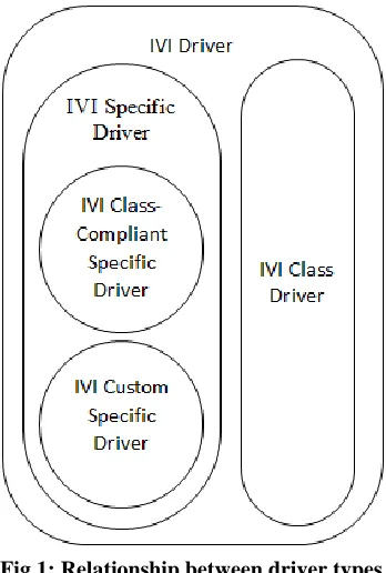
Figure 1 is a Venn diagram showing the common and specific drivers that developers can choose to match their
[image:2.612.355.529.337.595.2]applications needs. IVI driver is an instrument driver with inherent capabilities; it can directly communicate with instrument hardware or act as a pass-through layer to other IVI drivers. Developers need to choose an IVI driver as a specific driver or an IVI class driver. IVI specific driver is a driver that controls a specific instrument and directly communicates with the instrument hardware it can be class-compliant with other instrument interchangeability or not compliant with defined IVI class specification since it requires a custom API for specialized instrument. IVI class driver is an interchange instrument since it uses IVI class-compliant specific drivers. This class driver exports an API complying with defined IVI class specifications. IVI class driver are interchangeable when IVI-C and IVI-COM class-compliant specific drivers are used [5]. IVI Foundation promotes the programming standard for test instrument. It is important that vendor builds on an existing industry standard which allows interchanging instruments and provides high-performance software [6, 19].
Fig 1: Relationship between driver types
B. Test Automation
International Journal of Innovative Technology and Exploring Engineering (IJITEE) ISSN: 2278-3075,Volume-8 Issue-11, September 2019
Regression test is a way that a software test case is retained and reused for other testing. It is important for the regression tester to ensure that the continuing software improvement does not damage or affect other existing functionalities [15]. Software tools are used to automate some of the manual tasks because manual testing is tedious, error-prone and resource consuming. Theoretically, there is no fully automated testing possible when there are some activities, like result checking and some physical configuration are needed. Nonetheless, some degree of automation is needed to sustain the test and individual activities. Commercial software tools are used to reduce the test deployment time. The aim of this paper is to reduce testing time and increase productivity without involving human interaction on tedious and repetitive tasks that can possibly be done by using software tools. In some cases, planning for test automation is not simple since every product is different and regular commercial software tools might not fully support product test automation. Some of the tasks require the tester to consider the planning test automation which include specific needs, potential test for automation, consideration of existing testing tools, cost to build test automation tools, user training and impact on schedule of project [9,20,21]. Thus, the automated test requirements are derived from the software feature specifications. The test cases are written according to specific functional part of the SUT. In order to make sure every test case is applicable for each test feature, a precise description on purpose, input processing, outputs and method to handle error are established. The feature offered in SUT should be testable and some of the features are dependent or is an aggregation relation between them.
III. PROPOSED METHOD
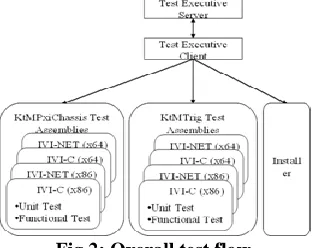
[image:3.612.313.531.360.543.2]The method starts to take place when SUT hardware setup is done. Figure 2 shows Test Executive Server and Test Executive Client starting to communicate. Before the test can be started, the test system must get to know the client hardware and software setup information. After the test system identifies the client configuration and makes necessary installation on the client, the server will start loading test into client. The client will start the test after it receives command from the server in sequential order. In this work the PXI Family Chassis Driver consists of two categories of driver, KtMPxiChassis and KtMTrig. Each driver categories will have 12 sets of tests that are a combination of IVI-C, IVI-NET, x86 and x64 platform.
Fig 2: Overall test flow
A. Server-Client
[image:3.612.92.251.597.721.2]The server-client concept in Figure 3 has been chosen in this work because it is one of the most feasible ways to manage multiple controllers by using a single computer. To fulfill all the test coverage, the software and hardware on the client will always change after completing a specific test. The Test Executive Server application has the capability to detect if there is a client alive and return the information for further action. The Test Executive Server will interactively send command and receive information from the client. The Test Executive Server will query the client status including existing hardware and software currently available on client side. Once it finishes the query it will continue to check and compare the test requirement if it meets the loaded test suite. If the software requirement is not correct, it will try to install the needed software. The Test Executive Server will continue to verify and download necessary test files from the shared file server. After verification, it will continue to load the test in the test suite. The Test Executive Server will continue to monitor for a summary test result sent from the client and record down the rest result sent by the client. The Test Executive Server is capable of handling multiple clients. Theoretically, it is an int32 and it can handle over 2 billion clients but because it is bound with the amount of threads running, the application run in .Net Framework 4.0 is only able to support 6549 of clients, each client will require 5 threads since .Net Framework 4.0 only supports 32768 threads.
Fig 3: Software Tool Server-Client interconnect
B. Server operation flow
4067 Retrieval NumberK15480981119/2019©BEIESP
DOI: 10.35940/ijitee.K1548.0881119
Published By:
Blue Eyes Intelligence Engineering & Sciences Publication
Controller
(System Controller)
[image:4.612.48.312.132.271.2]Figure 4 shows the application work under the Transport Layer to send and receive bytes directly through the TCP socket which gives advantage on performance when sending and receiving message. Writing a program at application layer is more feasible because it has framework support but in this work the application has its own custom protocol.
Fig 4: Architecture where the application occur
IV. INSTRUMENT
CONFIGURATION FOR SOFTWARE UNDER TEST (SUT)
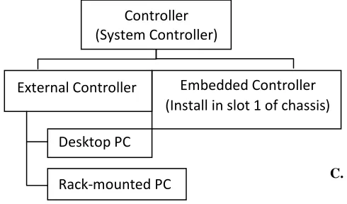
[image:4.612.302.558.444.588.2]The configuration can be as simple as a single controller and it can also grow to a large system that allows four chassis cascaded. In this work, Keysight PXI chassis is employed and the entire configuration is bonded with PXI chassis support configuration. Figure 5 shows type of controller to build the PXI system. The computer to control the chassis is known as the controller of system controller. Controller can either be external controller or an embedded controller. An external controller is a Windows-based PC; it can be a desktop PC or rack-mounted PC. The external controller interfaces to the chassis through a PCIe cable. An embedded controller is a small form factor PC which is Windows-based. This controller is designed for installation in the slot 1 chassis. M9037A is an embedded controller that occupies three expansion slots.
Fig 5: Type of controllers
A. Embedded controller configuration
In this work, an embedded controller comes with Windows Embedded Standard (WES) 7. This embedded controller is equipped with Intel i7-4700EQ 2.14GHz Quad core processor, the chipset is from Mobile IntelQM57Express, installed with 16GB DDR3L 1600MHz SODIMM RAM. For the PCIe
interconnectivity it has a Gen3.0 4 link (4x4), 2 link (x8, x16). The embedded controller uses 240 GB Solid-State Drive that will boost the controller performance. To use embedded
controller is straight forward since it only supports two versions of OS that is WES 7 64-bits and 32-bits and there is no need to use a system module or PCI host adapter. The embedded controller is specifically designed for PXI usage; it saves space since the space is dedicated inside the chassis.
B. Text fixtures
The fixture functional test was carried out using test fixtures. This test fixture will either act as output signal or input signal. There are two groups of tests that require fixture functional test; PXI Trig test and auto clock switching test. The PXI Trig test is to test the eight trigger lines at the backplane and the front panel trigger located in front of the chassis. The clock switching test is to verify the reference frequency phase lock whether the chassis is able to switch to the correct source according to priority clock source available.
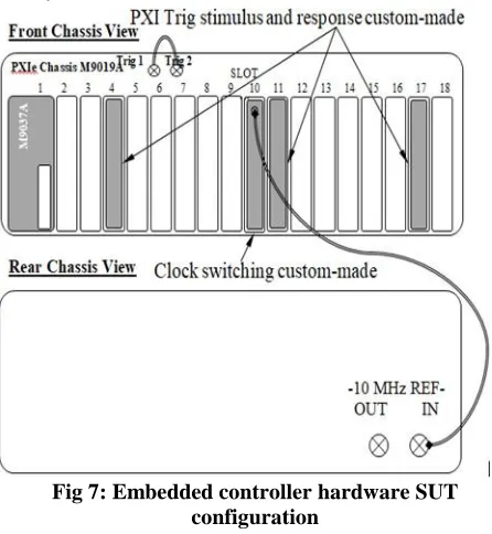
Figure 6 shows a PXI Trig stimulus and response custom-made module. It can send and receive 8-line PXI Trigger at the backplane. This signal is only propagating for a short distance before the signal integrity degrades. A large chassis system such as M9019A has eighteen slots needs a re-buffer trigger signal. The re-buffer is done by the trigger bridge on every eight slots, and 18 slot chassis have 2 two trigger bridges that make up three segments. This trigger bridge can be reserved and programmable routed. The custom-made module is inserted on each segment. In this work, the module is located at slot 4, slot 11 and slot 17. Another test that is required for this module is the two front panel trigger ports (SMB). This trigger port acts as input and output to the backplane eight trigger line PXI (0:7), segment 2. Fig 6: PXI Trig stimulus and response custom-made module
C. Test System Hardware Setup
The chassis and controller will be installed on a test rack for easy access and equipment management. In this work, the system has been setup only with a single controller and with a single chassis. Figure 7 shows a M9018A PXI chassis with slot 1 installed M9037A as an embedded controller, each of the slot 4, 11 and 17, installed with PXI Trig stimulus and response custom-made module and slot 10 with Clock Switching module.
Rack-mounted PC
Desktop PC
[image:4.612.55.300.476.620.2]International Journal of Innovative Technology and Exploring Engineering (IJITEE) ISSN: 2278-3075,Volume-8 Issue-11, September 2019
For the rest of the data collection in this work, the embedded controller will be M9018B, M9019A and M9010A. The M9037A is preinstalled withWES7 and the client is configured to immediately run when the controller boots up.
[image:5.612.304.579.56.236.2]The network port is connected to a multiple subnet local area network (LAN) where other clients are connected. The embedded controller supports display port (DP) as a digital display interface out but in this setup, did not require any human interface device (HID) since the whole testing run is done by the Test Executive Client.
Fig 7: Embedded controller hardware SUT configuration
V. RESULT AND DISCUSSION
The Test Executive Server-Client is developed to manage and implement testing activities. Tables 1 (a) and (b) summarize the test execution time for eight configurations by using two controllers and four types of chassis. Each of the configurations will need to go through two IVI set of tests, KtMPxiChassis and KtMTrig. Each of the IVI test consists of unit test, functional test and fixture functional test.
TABLE I (A) AUTOMATED TEST TIME FOR M9037A AND Z440
TABLE I (B) AUTOMATED TEST TIME FOR M9037A AND Z440
Test Configuration
Duration
(Seconds) M9018
A
-WE
S7
M
9018
B
-WE
S7
M
9019
A
-WE
S7
M
9010
A
-WE
S7
KtMPxiChassis Test 3011 2811 5455 5615
KtMTrig Test 2260 1920 2435 1471
Automated setup 378 378 378 378
Total per configuration 5649 5109 8268 7464
The automated test advantage is the setup time. It only takes 378 seconds to download and install PXI Chassis Driver, PXI Trig stimulus and response custom-made module driver, Fusion, IOLS and PCIe interface drivers. The Test Executive Server-Client has demonstrated that the setup time is reduced by 75.28% of the overall test time and can be calculated by using the equation below. The Test Executive Server-Client has substituted manual repetitive tasks and non-subjective operations. This newly developed tool allows developers and quality engineers to utilize their resources by adding more tests or develop more comprehensive tests rather than doing manual execution. In this work, PXI is a wide platform and it is designed to work interoperability with other modules, chassis and instruments. Because of the nature of the PXI interoperability, the scope of software quality testing becomes complex and time consuming. This Test Executive Server-Client method reveals that it can reduce testing time and it requires less effort to monitor the test. Software testing is adapting to the automation process because it performs better. In terms of automation, produce predictable result and consistent performance. Meanwhile, compared with manual execution, automated software tool creates less percentage of error in testing. Human execution is affected by adaptability. It is unpredictable, inconsistent and subject to human emotions. Engineer will normally handle more than one task and has a tendency to overlook a particular test execution when he or she tries to switch tasks.
A. KtMPxiChassis and KtMTrig IVI driver testing
The PXI Family Chassis installer package comes with two types of IVI driver: IVI-NET and IVI-C. It will also install two drivers, KtMPxiChassis and KtMTrig driver. Table II shows the testing duration according to IVI type and test category. The test category is divided into three groups; unit test, functional test and fixture functional test. All three test categories need to run on two platforms x86 and x64. The time taken to execute x86 and x64 test assemblies is almost the same since the number of the test cases is the same.
Test
Configuration
Duration
(Seconds) M9018
A
-W
IN10
M
9018
B
-WI
N
10
M
9019
A
-W
IN10
M
9010
A
-W
IN10
KtMPxiChassis Test 2819 1626 3254 3336
KtMTrig Test 1918 1974 2131 1351
Automated setup 378 378 378 378
[image:5.612.53.276.175.417.2] [image:5.612.40.290.543.775.2]4069 Retrieval NumberK15480981119/2019©BEIESP
DOI: 10.35940/ijitee.K1548.0881119
Published By:
Blue Eyes Intelligence Engineering & Sciences Publication
The test duration for functional test is higher than the
[image:6.612.54.295.159.291.2]unit test since it consists of multiple functions. This functional test is generated by combining a few related interface commands to become a useful system functional test. When developing a functional test, developer needs to take into consideration for valid use case when writing the functional test.
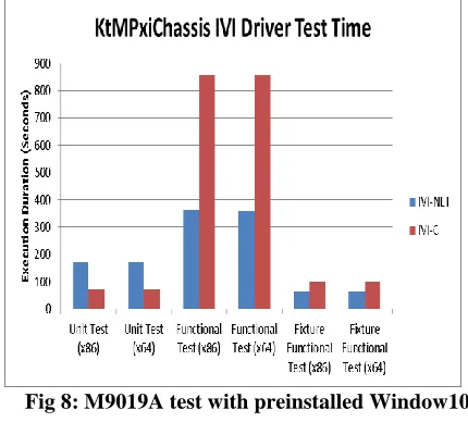
Table II: KtMPxiChassis IVI testing on M9019A with Z440 external controller
Unit Test (x86)
Unit Test (x64)
Functional Test (x86)
Functional Test (x64)
Fixture Functional
Test (x86)
Fixture Functional
Test (x64) IVI-NET
Test Duration (Seconds)
174 172 362 360 64 64
IVI-C Test Duration (Seconds)
75 75 856 855 98 99
[image:6.612.55.270.382.576.2]Figure 8 indicates that the functional test takes the longest time to complete both IVI-NET and IVI-C test. The IVI-C functional test alone takes up 83.1% from the total IVI-C. Meanwhile the IVI-NET needs up to 60% of the total test time. The fixture functional test is taking less time to complete compared to other test categories since it has fewer test cases if compared with unit and functional test.
Fig 8: M9019A test with preinstalled Window10
B. Manual Test Execution
The existing testing is carried out manually by the engineer. The manual test needs engineer to manually setup the test environment and run the test as per planned test. For each round when the hardware configuration changes, the testing environment may need to be setup again. The manual approach wastes time on test environment setup but it also needs human intervention during the test run.
Table III (a): Manual setup and test time
Test Configuration
Test Time
(Seconds) M9018
A
-W
IN10
M
9018
B
-WI
N
10
M
9019
A
-W
IN10
M
9010
A
-W
IN10
KtMPxiChassis 2819 1626 3254 3336
KtMTrig 1918 1974 2131 1351
Manual setup 1529 1529 1529 1529
Total per configuration 6266 5129 6914 6216
Table III (b): Manual setup and test time
Test Configuration
Test Time
(Seconds) M
9018
A
-WE
S7
M
9018
B
-WE
S7
M
9019
A
-WE
S7
M
9010
A
-WE
S7
KtMPxiChassis 3011 2811 5455 5615
KtMTrig 2260 1920 2435 1471
Manual setup 1529 1529 1529 1529
Total per configuration 6800 6260 9419 8615
International Journal of Innovative Technology and Exploring Engineering (IJITEE) ISSN: 2278-3075,Volume-8 Issue-11, September 2019
The final test result is not only on the actual result, it might need to consider human errors as a variable since the result might not be accurate if tester introduces error during setup or testing.
C. Comparison between manual and automated testing
The automated test execution is able to reduce 1151 seconds per configuration compared to manual test execution. By considering this work, test setup done by Test Executive Server-Client has a significant improvement. It reduces an average of 17.1% of eight tested configuration duration and can be calculated by using the equation (1):
The technique shows a clear advantage over traditional manual testing. It provides a platform to draft out the test with the current scope of testing interest and the test execution is fully automated. The test runs automatically after the hardware changes and the only effort needed is to make sure the client is running. A simple model to start a test is a single server connected with a client.
In this work, the software tool gives an elegant solution to centralize the control and it is easy to collect the test summary from each client. This helps developer to have a quick overall view of the software driver’s health. The software tools developed is a scalable model; it can deploy more than one Test Executive Server or Test Executive Client on the same network or multi-subnet network with multiple individual computers. The software tool is a portable application where the server and client applications developed in this work does not depend on Windows configuration and it can directly read and write its configuration settings into an accessible folder in the computer. The software tool is enhanced by connectivity. If Test Executive Server or Test Executive Client is disconnected, it will automatically reconnect. This solution is ready with auto remote or local testing. Developer can remotely execute a single test or query information from the server for immediate result without going through server. Easy maintenance or future upgrade, since the test assembly is loaded from the main program, this allows developer to make a change or add more tests without recompiling the whole solution. It is easy to maintain, the test is written in C# class form, it can be added into existing test assembly and easily call the newly added test by using the command which is structured per class and method name.
VI. CONCLUSION
The result shows that automated testing helps to improve testing duration and provide a platform to utilize the PXI chassis driver. The automated testing provides a quick setup for software environment and test execution. The server and client connect and deploy the testing automatically after the hardware is ready and booted into operating system. This
automated flow reduces developer resources on managing the testing. Based on one of the test configurations, the software tool has shown a reduction of 17.1% of the current average test duration. Furthermore, the testing environment and hardware configurations have a lot in common and yet each verified environment is structured to follow the PXI and IVI standard specifications. This software tool is to create a simple test infrastructure to support the test environment configuration and manage multiple SUT at a single point. The software tool supports concurrent execution of testing. Concurrent testing can be spawned explicitly by using a client application on the SUT controller. The software tool has a feature to
ACKNOWLEDGMENT
The authors would like to thank to Universiti Sains Malaysia and Research Grant RUI (1001/PELECT/8014049) and reviewers’ comments.
REFERENCES
1. Shuang Wang and Jeff Offutt, "Comparison of Unit-Level Automated Test Generation Tools," in International Conference on Software Testing, Verification, and Validation Workshops, Denver, CO, USA, 2009.
2. R. Venkatesh, U. Shrotri, A. Zare and S. Agrawal, "Cost-effective functional testing of reactive software," in International Conference on Evaluation of Novel Approaches to Software Engineering (ENASE), Barcelona, Spain, 2015.
3. PXI-2 PXI Software Specification, "PXI Systems Alliance," 18
October 2012. [Online]. Available:
http://pxisa.org/userfiles/files/PXI2_R2DOT4.pdf.
4. Transitioning to a PXI Test System, "keysight.com," 20 July 2016. [Online].Available:
5. http://literature.cdn.keysight.com/litweb/pdf/5992-1652EN.pdf?id=278204
6. 2. [Accessed 1 May 2017].
7. I.-3. D. A. Specification, "ivifoundation.org," 07 February 2017. [Online].
Available:
8. http://www.ivifoundation.org/downloads/Architecture%20Specificat ions/I VI-3.1_Architecture_2017-02-07.pdf. [Accessed 1 May 2017].
9. IVI-6.3: IVI VISA PXI Plug-in, "IVI Foundation," 11 October 2013.
[Online].Available:http://www.ivifoundation.org/downloads//Prot ocol%20 Specifications/ivi63.pdf.
10. K. Fertitta, "Simplifying test system development with IVI.NET," in AUTOTESTCON, 2012.
11. Y. Sun, H. Qian and X. Liu, "Evaluation and Measurement of Software Testing Process Quality Applicable to Software Testing Laboratory," in Asia-Pacific Software Engineering Conference (APSEC), New Delhi, 2015.
12. Jeff Tian, Software Quality Engineering: Testing, Quality Assurance, and Quantifiable Improvement, 1 ed., Wiley-IEEE, 2005, pp. 15-337.
13. Jogannagari Malla Reddy and S.V.A.V.Prasad, "The Role of Verification and Validation in Software Testing," in 3rd International Conference on Computing for Sustainable Global Development (INDIACom), New Delhi, 2016.
4071 Retrieval NumberK15480981119/2019©BEIESP
DOI: 10.35940/ijitee.K1548.0881119
Published By:
Blue Eyes Intelligence Engineering & Sciences Publication
15. S. R. Roberto Pietrantuono, "On adaptive sampling-based testing for software reliability assessment," in IEEE 27th International Symposium on Software Reliability Engineering, 2016.
16. F. Lei and S. Xingzhe, "Design of the Instrunment Soft Panel using Windows Presentation Foundation," in Fifth International Conference on Instrumentation and Measuremt, Computer, Communication and Control, Qinhuangdao, 2015.
17. 14. B. Lima and J. P. Faria, "An Approach for Automated Scenario-based Testing of Distriuted and Heterogeneous Systems," 10th International Joint Conference on Software Technologies (ICSOFT), pp. 1-10, 2015.
18. 15. Vishawjyoti;Dr Parul Gandhi, "A Survey on Prospects of Automated Software Test Case Generation Method," in 3rd International Conference on Computing for Sustainable Global Development (INDIACom), New Delhi, 2016.
19. 16. F. Gao and F. Deng, "Design of A Networked Embedded Software Test Platform Based on Software and Hardware Cosimulation," in IEEE International Conference on Software Quality, Reliability and Security Companion, Vienna, 2016. 20. 17. R. Verret, "IVI Revisited: Building Next-Generation Test
Systems with Open FPGAs while Preserving Software APIs," in IEEE AUTOTESTCON, Schaumburg, IL, 2013.
21. 18. PXI-7 PXI MultiComputing Hardware Specification, "PXI System Allliance," 16 September 2009. [Online]. Available: http://pxisa.org/userfiles/files/Specifications/PXIMC_HW_SPEC_R 1.pdf.
22. 19 Keysight M9018B and M9019A PXIe Chassis, "keysight.com," Keysight, 23 September 2016. [Online]. Available:
http://literature.cdn.keysight.com/litweb/pdf/5992-1481EN.pdf?id=273493 23. 8. [Accessed 1 May 2017].
24. 20. Keysight M9010 PXIe Chassis, "keysight.com," 16 November 2016.[Online]. Available:
25.
http://literature.cdn.keysight.com/litweb/pdf/5992-1707EN.pdf?id=2811786. [ Accessed 1 May 2017]. 26. 21. Keysight PC Tested Configuration with PXI/AXIe,
"keysight.com," 20 June 2017. [Online]. Available: http://literature.cdn.keysight.com/litweb/pdf/5990-7632EN.pdf. [Accessed 1 May 2017].
AUTHORS PROFILE
Ng Wai Shyan graduated from the Universiti Malaysia Sabah with Bachelor of Engineering (Electrical & Electronic Engineering) (Hons) in 2006 and M.Sc. Electronic Systems Design Engineering from Universiti Sains Malaysia in 2017. Ng Wai Shyan worked in as test engineer on variety of industries include medical, automotive and industrial product testing. Currently Ng Wai Shyan is a test engineer at Keysight Technologies and his main area is software testing. As a test engineer he is responsible for define and develop testing
methodologies for new product releases.
MOHAMAD KHAIRI ISHAK was born in Kedah, Malaysia. He received the B.Eng degree in electrical and electronics engineering from the International Islamic University Malaysia (IIUM), the MSc. In Embedded System, from the University of Essex and PhD from the University of Bristol, United Kingdom. Currently, he is a Senior Lecturer in Mechatronics Engineering at School of Electrical and Electronic Engineering, Universiti Sains Malaysia. His research interests are Embedded System, Real-Time Control Communications and Robotics. Emphasis is given towards the development of theoretical and practical methods which can be practically validated. Recently,
significant research effort has been directed towards important industrial issues of embedded networked control systems and Internet of Things (IoT)
MOHAMAD FAUZI PACKEER
MOHAMAED was born in Kuala Lumpur, Malaysia in 1978. He received the B.Eng. degree in electrical and electronics engineering (with distinction) from the Universiti Tenaga Nasional (UNITEN) Kajang, Selangor, Malaysia in 2002, the M.Sc. degree in electronics system design engineering from the Universiti Sains Malaysia (USM), Nibong Tebal, Pulau Pinang in 2010, and Ph.D. degree in electrical and electronics
engineering from The University of Manchester (UoM), Manchester, United Kingdom in 2015. In 2015, he joined the School of Electrical and Electronics Engineering, Universiti Sains Malaysia (USM), as a Senior Lecturer. He has 7 years industrial experiences back from 2002 to 2009 in semiconductor