UNIVERSITI TEKNIKAL MALAYSIA MELAKA
A STUDY TO DETERMINE THE BEST COMBINATION OF
FDM PROCESS PARAMETERS USING TAGUCHI METHOD TO
OPTIMIZE THE BUILD TIME AND SURFACE QUALITY
This report submitted in accordance with requirement of the Universiti Teknikal Malaysia Melaka (UTeM) for the Bachelor Degree of Manufacturing Engineering
(Manufacturing Design) (Hons.)
by
NG MEE CHIN B051210015 921222-07-5478
UNIVERSITI TEKNIKAL MALAYSIA MELAKA
BORANG PENGESAHAN STATUS LAPORAN PROJEK SARJANA MUDA
TAJUK: A Study To Determine The Best Combination Of FDM Process Parameters Using Taguchi Method To Optimize Build Time And Surface Quality
SESI PENGAJIAN: 2015/16 Semester 2 Saya NG MEE CHIN
mengaku membenarkan Laporan PSM ini disimpan di Perpustakaan Universiti Teknikal Malaysia Melaka (UTeM) dengan syarat-syarat kegunaan seperti berikut: 1. Laporan PSM adalah hak milik Universiti Teknikal Malaysia Melaka dan penulis. 2. Perpustakaan Universiti Teknikal Malaysia Melaka dibenarkan membuat salinan
untuk tujuan pengajian sahaja dengan izin penulis.
3. Perpustakaan dibenarkan membuat salinan laporan PSM ini sebagai bahan pertukaran antara institusi pengajian tinggi.
4. **Sila tandakan (√)
SULIT
√ TERHAD
TIDAK TERHAD
(Mengandungi maklumat yang berdarjah keselamatan atau kepentingan Malaysia sebagaimana yang
Termaktub dalam AKTA RAHSIA RASMI 1972)
(Mengandungi maklumat TERHAD yang telah ditentukan oleh organisasi/badan di mana penyelidikan dijalankan)
Alamat Tetap:
8-7-13, Persiaran Paya Terubong Satu, Ralau, 11900 Bayan Lepas Pulau Pinang.
Tarikh: _________________________
Disahkan oleh:
Cop Rasmi:
Tarikh: _______________________
DECLARATION
I hereby, declared this report entitled “A Study To Determine The Best Combination Of FDM Process Parameters Using Taguchi Method To Optimize The Build Time And Surface Quality” is the results of my own research except as
cited in references.
Signature : ……….
Author’s Name : NG MEE CHIN
APPROVAL
This report is submitted to the Faculty of Manufacturing Engineering of UTeM as a partial fulfillment of the requirements for the degree of Bachelor of Manufacturing Engineering (Manufacturing Design) (Hons.). The member of the supervisory is as follow:
………
ABSTRAK
Kaedah Taguchi adalah alat yang berkesan diperkenalkan untuk pengoptimuman produk atau proses kualiti. Produk yang dihasilkan oleh ABS Fused Deposition Model (FDM) mempunyai hasil yang tersendiri yang berbeza dengan perubahan parameter proses mesin seperti orientasi membina, ketebalan lapisan dan sudut raster. Prestasi bahagian yang dihasilkan melalui Stratasys FDM 400 mesin MC diperhatikan masa membina dan diukur untuk kekasaran permukaan. Dalam usaha untuk mencapai prestasi optimum bahagian yang dihasilkan, Kaedah Taguchi telah dilaksanakan. Dalam projek ini, pelbagai ortogon daripada L9 (33) telah digunakan
dan 9 keping sampel telah dibina untuk 3 parameter iaitu: membina orientasi, ketebalan lapisan dan sudut raster dengan 3 tahap setiap parameter. Sampel itu direka menggunakan SolidWorks dan dibina menggunakan Stratasys FDM 400 mesin MC. Sampel diperhatikan masa membina dan kemudian diuji untuk kekasaran permukaan menggunakan Mitutoyo Surftest SJ 301. Keputusan telah diperolehi dan data dianalisis. Data menunjukkan bahawa sampel dengan kombinasi parameter XY orientasi, ketebalan lapisan 0.03302 cm dan sudut raster 900 mencapai masa
membina yang paling singkat manakala data yang menunjukkan bahawa sampel dengan kombinasi parameter XY orientasi, ketebalan lapisan 0.01778 cm dan raster sudut 300 mencapai kekasaran permukaan purata yang paling rendah mengikuti nilai
ABSTRACT
Taguchi Method is an effective tool introduced for the optimization of a product or process quality. The ABS product produced by Fused Deposition Modeling (FDM) has its own unique result which varies with the changes of the process parameters of the machine such as build orientation, layer thickness and raster angles. The performance of the part produced via Stratasys FDM 400 MC machines was observed for build time and measured for surface roughness. In order to achieve the optimum performance of the produced part, the Taguchi Method was employed. In this project, an orthogonal array of L9 (33) was used and 9 pieces of samples were
determined for 3 parameters namely: build orientation, layer thickness and raster angles with 3 levels each. The sample was designed using SolidWorks and fabricated using Stratasys FDM 400 MC machines. The samples were observed for build time and then tested for surface roughness using Mitutoyo Surftest SJ 301. The results were obtained and data was analysed. The data shows that the samples with parameters combination of XY orientation, layer thickness of 0.03302 cm and raster angle of 900 achieved the shortest build time while the data shows that the samples
with parameters combination of XY orientation, layer thickness of 0.01778cm and raster angle of 300 achieved the lowest average surface roughness, Ra value
DEDICATION
I would like to dedicate this work to my
Beloved parents
Dearest siblings
Honorable supervisor and lecturers
ACKNOWLEDGEMENT
I would like to express my gratitude to my supervisor, Dr. Shajahan bin Maidin for the continuous encouragement, invaluable supervision, timely suggestions and inspired guidance in bringing the Final Year Project to a successful completion.
TABLE OF CONTENT
Abstrak i
Abstract ii
Dedication iii
Acknowledgement iv
Table of Contents v
List of Tables ix
List of Figures x
List Abbreviations, Symbols and Nomenclatures xiii
CHAPTER 1: INTRODUCTION 1
1.1 Introduction 1
1.2 Problem Statement 2
1.3 Objective 3
1.4 Scope 4
CHAPTER 2: LITERATURE REVIEW 5
2.1 Additive Manufacturing (AM) 5
2.3 Molten Material Systems 8
2.3.1 Fused Deposition Modeling (FDM) 9
2.3.2 FDM Process 9
2.3.3 FDM Materials 10
2.3.4 Application of FDM 14
2.3.5 Advantages of FDM 14
2.3.6 Disadvantages of FDM 15
2.4 Application of AM 16
2.5 Advantages of AM 19
2.6 Disadvantages of AM 20
2.7 Taguchi Method Background 21
2.7.1 Selection of Design or Process Parameters 22
2.7.2 Design of Experiment 23
2.7.3 Orthogonal Arrays 28
2.7.4 Analysis of Variance 29
2.7.5 Signal to Noise Ratio 31
2.8 FDM Parameter Optimization 36
2.8.1 Surface Roughness 36
2.8.2 Build Time 37
2.8.3 Build Orientation 38
2.8.4 Stair-case effect 40
2.8.6 Layer Thickness 41
2.8.7 Part Deposition 42
CHAPTER 3: METHODOLOGY 43
3.1 Introduction 43
3.2 Flow Chart 44
3.3 Project Implementation Procedure 47
3.3.1 Phase 0: Planning 47
3.3.2 Phase 1: Detail Design 48
3.3.3 Phase 2: Preparation of Specimen 50
3.3.4 Standard Operating Procedure 51
3.3.4.1 Stratasys FDM 400 MC machines 51
3.3.4.2 Fabrication of Mounting Brackets 55
3.3.4.3 Mitutoyo Surftest SJ-301 56
3.3.4.4 Meiji Stereo Microscope 58
3.3.5 Phase 3: Collection of Data 59
3.3.6 Phase 4: Result and Analysis 59
3.3.7 Phase 5: Conclusion and Recommendation 60
CHAPTER 4: RESULT AND DISCUSSION 61
4.1 Introduction 61
4.3 Build Time 63
4.3.1 Analysis of data 63
4.3.2 ANOVA Analysis 67
4.4 Surface Roughness 71
4.4.1 Analysis of data 71
4.4.2 Macroscopic Inspection 79
4.4.3 ANOVA Analysis 81
4.5 Sustainability Development 85
CHAPTER 5: CONCLUSION AND RECOMMENDATION 87
5.1 Conclusion 87
5.2 Recommendation 89
REFERENCES 91
LIST OF TABLES
2.1 Basic FDM material and their characteristics 11
2.2 L-4 (23) Orthogonal Array 28
3.1 List of parameters with its values in each level 51
3.2 The Orthogonal Array L9 (33) derived using Taguchi method 55
4.1 Different combination of parameter settings for each experimental run 62
4.2 Build Time Result for mounting brackets 63
4.3 Percentage contributions of parameters on build time 68
4.4 P-value analysis 70
4.5 Surface Roughness Result for 9 mounting brackets produced 72
4.6 Percentage contributions of parameters on surface roughness 82
LIST OF FIGURES
2.1 Eight Generic AM Processes 6
2.2 FDM Process 9
2.3 AM application timeline 17
2.4 Prosthetic Jaw 18
2.5 Taguchi Loss of Function 22
2.6 Nine steps used to investigate a process and optimize the performance of the
process 24
2.7 Experimental Design using Orthogonal Array 27
2.8 Smaller is Better Approach 32
2.9 Larger is Better Approach 33
2.10 Nominal is Better Approach 34
2.11 Stair stepping effect 40
3.1 Flow of the Project 44
3.2 Isometric View of Mounting Bracket in XY direction 48
3.3 Isometric View of Mounting Bracket in XZ direction 49
3.4 Isometric View of Mounting Bracket in YZ direction 49
3.5 Detail design of Mounting Bracket with dimensions 50
3.7 Ultrasonic Tank 54
3.8 Mounting Brackets Produced using Stratasys FDM 400 MC machines 55
3.9 Average Surface Roughness, Ra value taken using Mitutoyo
Surftest SJ-301 56
3.10 Touch Probe is used to measure the Average Surface Roughness, Ra
value using Mitutoyo Suftest SJ-301 57
3.11 Meiji Stereo Microscope 58
4.1 Build time for each experimental run 65
4.2 Percentage contributions of parameters on build time 68
4.3 Pareto Chart on build time 69
4.4 Average Surface Roughness, Ra value for each experimental run 75
4.5 Voids effect on different layer thickness 76
4.6 Stair case effect 77
4.7 Voids present in a specimen with raster angle of 600 78
4.8 Experimental run 1 is the combination of XY orientation,
layer thickness of 0.01778 cm and raster angle of 300 gives the
lowest surface roughness which indicates the best surface quality 79
4.9 Experimental run 9 with the combination of YZ orientation,
layer thickness of 0.03302cm and raster angle of 450 gives the
highest surface roughness which indicates bad surface quality 80
LIST OF ABBREVIATIONS, SYMBOLS AND
NOMENCLATURE
ABS - Acrylonitrile butadiene styrene
Adj MS - Adjusted Mean Square
Adj SS - Adjacent Sum of Squares
AM - Additive manufacturing
AMC - Advanced Manufacturing Center
ANOVA - Analysis of Variance
BASS - Break Away Support System
BS - British Standard
CAD - Computer-aided Design
CAM - Computer-aided Manufacturing
CNC - Computer Numerical Control
DOE - Design of Experiment
EtO - Ethylene oxide
FDM - Fused Deposition Modeling
FKP - Fakulti Kejuruteraan Pembuatan
GA - Genetic Algorithm
ISO - International Standard Organisation
PC-ABS - Polycarbonate-Acrylonitrile butadiene styrene
PC-ISO - Polycarbonate ISO
PPSF - Polyphenylsulfone
Ra - Roughness Average
S/N - Signal to Noise
SOP - Standard Operating Procedure
STL - Stereolithography
ULTEM 9085 - Polyetherimide
US - Unites States
UTeM - Universiti Teknikal Malaysia Melaka
CHAPTER 1
INTRODUCTION
This chapter introduces the project and briefly describes about the objectives and the scope of the study. This chapter will give an overview on the implementation of the project.
1.1 Introduction
Resit and Edwin (1991) proposed that Taguchi Method is a popular method used to provide systematic and efficient methodology for design optimization. Therefore, an efficient way to enhance competitiveness in improving the quality of products is to conduct Taguchi Methods to make products and processes robust during early product design and development stage. Taguchi method focuses on four business objectives in market which are short development time, low cost, high performance and high quality.
computer-aided design (CAD) software automatically by using layers deposition of extrusion materials. In fact, fused deposition modeling is one of the additive prototyping processes which can generate a prototype from plastic material by laying track of semi molten plastic filament on to a platform in a layer wise manner from the top to bottom. The layer generation result from solidification is because of heat conduction. In fact, reduction of product development cycle time is a major consideration in industries to remain competitive in the market place. Therefore, traditional product development technology has been changed to rapid fabrication techniques, for instance, additive prototyping processes.
The main purpose of the project is to determine how the best combination of the parameters which are the layer thickness, raster angle and build orientation influence the build time and surface roughness of Fused Deposition Modeling produced test specimen. Experiments will be conducted using Taguchi’s design of experiments with three levels for each factor. The combined set of different parameters can be produced using Orthogonal Arrays. Furthermore, the project studies the significance parameters that affect the build time and surface roughness of the FDM process using Analysis of Variance respectively.
1.2 Problem Statement
eliminate cost for post-processing processes to obtain desired surface quality. In addition, Royal Academy of Engineering (2013) proposed that AM technology is not as competitive as a conventional method such as injection moulding, casting and CNC machining. In fact, build orientation, layer thickness and raster angle are those process parameters that will influence the build time and surface roughness. The combinations of the different settings of the parameters will produce parts with different build time and surface roughness. Design of experiment using Taguchi methods to determine best combinations and the number of runs of the experiment will be carried out. The best combinations of the different settings of the parameters for build time and surface roughness are then identified.
1.3 Objective
The objective of this study is as follows:
i. To optimize the fused deposition modeling process parameters by using Taguchi’s method.
ii. To produce CAD model of FDM test specimen and build them on a FDM machine using ABS material.
iii. To determine combinations of the different settings of the FDM parameters in which it can produce the shortest build time and best surface quality.
1.4 Scope
CHAPTER 2
LITERATURE REVIEW
This chapter discusses about the related knowledge of the project which cover the introduction of the additive manufacturing, fused deposition modeling and Taguchi Method.
2.1 Additive Manufacturing (AM)
Furthermore, Pandey et al. (2006) have presented that AM is not similar compared to lathing, milling and grinding as they will use material removal process to produce the shape of the product.
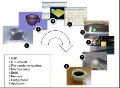
[image:24.612.122.534.273.575.2]2.2 Eight Generic AM Processes
Figure 2.1: Eight Generic AM Processes (Gibson et al., 2010)