UNIVERSITI TEKNIKAL MALAYSIA MELAKA
DESIGN AND DEVELOPMENT OF WIRELESS SWITCHING
CONTROL (WSC) USING SMARTPHONE
This report is submitted in accordance with the requirement of the Universiti Teknikal Malaysia Melaka (UTeM) for the Bachelor of Electronics Engineering
Technology (Telecommunications) with Honours.
by
AHMAD TAQIYUDDIN BIN MOHD ABDAH
B071310166
910207-01-5211
i
DECLARATION
I hereby, declared this report entitled “Design and Development of Wireless Switching Control using Smartphone” is the results of my own research except as cited in the references.
Signature : ……….
Author‟s Name : ……….
ii
APPROVAL
This report is submitted to the Faculty of Engineering Technology of UTeM as a partial fulfillment of the requirements for the degree of Bachelor of Electronics Engineering Technology (Telecommunications) with Honours. The member of the supervisory is as follow:
iii
ABSTRAK
iv
ABSTRACT
This project proposes the design and development of Wireless Switching Control (WSC) using a Smartphone. Wireless Switching Control (WSC) is a system that controls all appliances such as a lamp and fan. The main objective of this project helps to understand the operation theory of wireless communication and also to design a smartphone application using Blynk Platform to connect with the Wireless Switching Control (WSC). The functionality of the system depends on the operating distance of the device. In addition, it can save the cost of electricity for lighting can be controlled to suit the user. Generally, most home appliances controlled from a distance using a remote control. Wireless Switching Control (WSC) created a system for controlling home lighting over long distance, which replaces the remote control using mobile smart phone (smartphone). The smartphone will function as a remote control, an application was designed using Blynk Plaform. Blynk is an application used for designing applications intended. A hardware microcontroller NodeMCU module which is used to connect the smartphone to the electrical equipment. The system has been tested by developing a mini model and take into account the situation in the domestic home. The test is based on the level of control for wirelessly using Wi-Fi and the distance between the lamp and the smartphone. The results of this test, the system can be used on equipment or other home appliances for the purpose of controlling or adjustment
v
DEDICATION
vi
ACKNOWLEDGEMENT
First of all, I would like to express my full appreciation to the management of Universiti Teknikal Malaysia Melaka, for giving me an opportunity to do this bachelor‟s degree project.
I also like to show my token of appreciation to our lecturers at Universiti Teknikal Malaysia Melaka who really helped me a lot throughout finishing my project. They don‟t hesitate to teach me whenever I need help even when I make mistakes.
Other than that, I would like to thank my friends and coursemates who really helped in sharing their information in finishing my project.
Furthermore, I also like to thank my colleagues who helped me directly or indirectly during the journey in finishing this task.
Last but the not least, I wish to thank once again to everyone involved in completing my project and report successfully.
vii
TABLE OF CONTENT
Declaration i
Approval ii
Abstrak iii
Abstract iv
Dedication v
Acknowledgement vi
Table of Content vii
List of Tables x
List of Figures xi
List of Abbreviations, Symbols and Nomenclatures xiii
CHAPTER 1: INTRODUCTION 1
1.0 Introduction 1
1.1 Background 1
1.2 Problem Statement 2
1.3 Objective 2
1.4 Work Scope 3
CHAPTER 2: LITERATURE REVIEW 4
2.0 Introduction 4
2.1 Background 4
2.2 Wireless Switching Control 5
2.2.1 Wireless 5
2.2.2 Switching 5
2.2.3 Control 5
2.3 Wireless Communication in Technology 6
2.3.1 Infrared (IR) 6
2.3.2 Radio Frequency (RF) 6
2.3.3 Bluetooth 8
viii 2.4 Hardware 9
2.4.1 Microcontroller 9
2.4.1.1Arduino Platform 9
2.4.1.2PIC 13
2.4.2 Sensor 14
2.4.2.1 Light Sensor 14
2.4.2.2 PIR Motion Sensor 15
2.4.2.3 Gas Sensor 16
2.4.3 Acuator 17
2.4.3.1 Relay Module 17
2.5 Software Development Tools 18
2.5.1 MIT App Inventor 18
2.5.2 Android Studio 19
2.5.3 Basic4Android 20
CHAPTER 3: METHODOLOGY 21
3.0 Introduction 21
3.1 Overall System Block Diagram 21
3.2 System Overview 23
3.3 Electrical Hardware Review 24
3.4 NodeMCU 24
3.4.1 NodeMCU Module (ESP8266-12E) 26
3.4.2 Advantages of NodeMCU Module (ESP8266-12E) 26
3.5 Blynk Platform 27
3.5.1 How Blynk Works 27
3.6 Relay Module 28
3.7 PIR Motion Sensor 29
3.7.1 PIR Sensor Operation and Detection Area 29
3.8 Power Supply 5V and 9V 30
3.8.1 Step by Step to Make Power Supply 30 3.8.1.1Design Circuit in Proteus 30 3.8.1.2Etching Process of Power Supply 31
ix 3.10 Wireless Switching Control System of This Project 34
CHAPTER 4: RESULT & DISCUSSION 35
4.0 Introduction 35
4.1 Power Supply 5V and 9V 35
4.2 Basic Circuit Operation in This Project 36 4.3 Relationship between power supply and operation of circuit Functions 36
4.4 Time Delay for Sending The Data 39
CHAPTER 5: CONCLUSION & FUTURE WORK 40
5.0 Introduction 40
5.1 Conclusion 40
5.2 Recommendations 41
REFERENCES 42
APPENDICES 44
A Gantt Chart (Project Planning) 44
x
LIST OF TABLES
2.1 Transmitter Pin Function 7
2.2 Receive Module Pin Function 7
2.3 Comparison between Infrared, Radio Frequency, Bluetooth and Wi-Fi 8
2.4 Comparison between Arduino Uno, Mega, and Due. 12
2.5 Function of the Relay Connection 17
3.1 NodeMCU Pin Out 26
4.1 Operation +5Volt Power Supply 37
4.2 Operation +9volts Power Supply 38
xi
LIST OF FIGURES
2.1 Diagram of RF Transmitter and RF Receiver 6
2.2 The pin of Arduino Uno Board 10
2.3 Arduino Mega Board 11
2.4 Arduino Duemilanove Board 12
2.5 PIC Microcontroller 13
2.6 Light Sensor 14
2.7 PIR Motion Sensor 15
2.8 Range of Passive Infrared (PIR) Sensor 15
2.9 Gas Sensor Module 16
2.10 Relay Module 17
2.11 MIT Inventor Apps 18
2.12 Android Studio Apps 19
2.13 Basic4Android Apps 20
3.1 Methodology Flowchart 22
3.2 System Overview 23
3.3 NodeMCU (ESP8266-12E) 24
3.4 ESP8266-12E Pin Out 25
3.5 NodeMCU Pin Out. 25
3.6 NodeMCU connected to Blynk Platform 26
3.7 Blynk Platform 27
3.8 Blynk Flow Concept 28
3.9 Relay Module Board 28
3.10 PIR Sensor Module 29
3.11 Power Supply Circuit in Proteus 30
3.12 Power Supply Track line 31
3.13 Power Supply in 3D Visualizer 31
3.14 Track line in Laminate Paper 32
3.15 UV Curing Station 32
3.16 Etcher Machine 32
xii
3.18 Power Supply Track Line Board 33
3.19 Wireless Switching Control System Flowchart 34
4.1 Power Supply 35
4.2 Basic Circuit of Wireless Switching Control 36
4.3 Figure of Vout vs Vin +5V 37
xiii
LIST OF ABBREVIATIONS, SYMBOLS AND
NOMENCLATURE
AC - Alternating Current CCTV - Closed-circuit Television DC - Direct Current
GND - Ground
IDE - Integrated Development Environment IoT - Internet of Things
LDR - Light Dependent Resistor LED - Light Emitting Diode
MIT - Massachusetts Institute of Technology PCB - Printed Circuit Board
PIR - Passive Infrared Sensor UI - User Interface
USB - Universal Serial Bus VB - Visual Basic
VIN - Input Voltage VOUT - Output Voltage Wi-Fi - Wireless Fidelity
1
CHAPTER 1
INTRODUCTION
1.0 Introduction
This chapter discusses about background, problem statement, objective and work scope of this project. The problem statement states the aim why this project is carried out.
1.1 Background
Wireless Switching Control (WSC) is a system that controls all appliances such as a lamp and fan. The system performance is same as smart home automation. As example their performance for controlling the property home equipment, for instance illumination connected with lighting of light, speed of fan, heat connected with air-condition and so on. This system is used to improve the technology for home automation by using smart phone application and web server. Users can use any options to help them to control on their residence automation system. Therefore, it is easier to use and it also provides comfort to the user to control in long distances.
2
1.2 Problem Statement
The cost of living is getting higher day by day; users are desperate to cut all of those living costs. Electrical power is one of the costs that its price keeps increasing each passing year. One of the easiest ways to control the cost of users electrical cost is to control and monitor the usage of the home appliances around the house.
We disable to control the electrical appliances from outside for security purposes. As a security purpose to prevent from danger when people came home late.
Disabled people meet barriers to make their daily works. However, technology is helping to lower many of these barriers and also give a lot of benefit to the disabled people. By using this application it also can help and ease for handling a wider range of activities independently.
1.3 Objective
The objectives of this project are as follows:
i. To understand the operation theory of wireless communication.
ii. To design a smartphone application using Blynk Platform to connect with the wireless switching control.
3
1.4 Work Scope
Smartphone application uses to control home appliances such as lamp and fan. Sometimes we forget to closed appliances at home when we at the outside of the house. Normal switch is difficult to make a switching when at the outside of the house and outdated. For help by following the development of technology, the smartphone is best idea to make a controlling home appliance using an application. The application will monitor the condition of home appliances, whether it is on or off.
The wireless switching control can cover depends on router signal strength. The connection range of Wi-Fi module depends on the type of Wi-Fi module normally the range accommodates in a house only. Another connection, it also can be connected to the web server or mobile application for controlling outside the house.
4
CHAPTER 2
LITERATURE REVIEW
2.0 Introduction
This chapter will contain the research and information from a thesis or journal about the concepts that related to project and there are several important things need to be taken for study case that should be focuses. This chapter also includes the details of the component that used for designed the wireless switching control and the comparison of each other. All the information has been researched from different resource as the references in order to take out the basic idea in producing the best yield from that discussed in this chapter.
2.1 Background
5
2.2 Wireless Switching Control
2.2.1 Wireless
According to (Ishiguro & Huang, 2011), Wireless mean communication of information between two or more transceivers that connected without using wires. For example, there are many types of wireless device such as infra-red, radio frequency, Bluetooth, Wi-Fi and satellite. Radio frequencies are the commonly used in wireless technology. By utilizing wireless communication has more benefit between using electrical conductor such as increase-including cost savings, flexibility and power consumption.
2.2.2 Switching
Normal switch is outdated for make switching in home appliances. The renewal technology for the switching is the combination between normal switch and electronic switch means that can use remote to make a switch. Relay module is an electronic switch normally that be used to make control a switch on and off (Balasubramanian & Oral 1992).
2.2.3 Control
6
2.3 Wireless Communication in Technology
Nowadays, Internet of Things (IoT) is a new communication among technologies. Wireless communication without using wire is the best source to send data in further the distance to control home appliances. The transmitted data can be everywhere exceeding the distance.
2.3.1 Infrared (IR)
According to (Rose Mary, 2011), it was explained about Infrared (IR) communication data through the light radiation. Infrared is an electromagnetic communication to send the data and received the data in the medium range. The communication cannot have any barriers between transmitter and receiver. For more knowledge, infrared is frequently used in television remote controls.
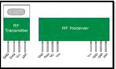
[image:20.595.219.455.498.638.2]2.3.2 Radio Frequency (RF)
Figure 2.1: Diagram of RF Transmitter and RF Receiver (Kushagra, 2012)
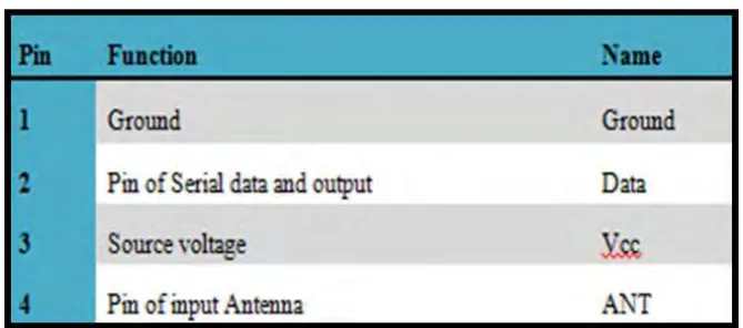
7 receive radio signals between two devices and is regularly desirable to communicate with another device wirelessly. Figure 2.1 shows the diagram of RF transmitter and also RF receiver. RF Transmitter has four pins which are GND pin, Data pin, Vcc pin and ANT pin. This RF module must be connected to the encoder and decoder. For an RF transmitter module, it must be connected with the encoder and the RF receiver must be connected to a decoder. Table 2.1 and 2.2 were displayed the pin function on the transmitter and receiver.
[image:21.595.169.504.463.611.2]Table 2.1: Transmitter Pin Function (Kushagra, 2012)
8 2.3.3 Bluetooth
Bluetooth is a wireless second technology that is famous before Wi-Fi technology. It can transmit and received the data around 10 meters for the distances using short-wavelength UHF and for the frequency around 2.4 to 2.485GHz. Purpose to (Jingfu, 2005) The Bluetooth module circuit design is on the basis of two ICs, SiW1701 and SiW1750. The latter one is used for the Baseband, and the other is for the RF parts. The external control of the module is connected through two ports (USB and UART) to exchange data.
2.3.4 Wi-Fi
[image:22.595.150.547.534.665.2]Reported that (Li et al. 2009) Wireless Fidelity are the latest technology, that are popular in the world of transmitting data fast and long distance. Wi-Fi used 2.4GHz frequency which can use CLOUD to send the data and information on long range and also can communicate between the modules such as ESP8266 modules. Wi-Fi is module price are not expensive and any people can make their own project in the communication system.
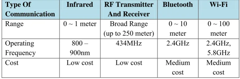
Table 2.3: Comparison between Infrared, Radio Frequency, Bluetooth and Wi-Fi (Li et al. 2009)
Type Of
Communication
Infrared RF Transmitter
And Receiver
Bluetooth Wi-Fi
Range 0 ~ 1 meter Broad Range
(up to 250 meter) 0 ~ 10 meter 0 ~ 100 meter Operating
Frequency 900nm800 – 434MHz 2.4GHz 2.4GHz, 5.8GHz
Cost Low cost Low cost Medium
9
2.4 Hardware
2.4.1 Microcontroller
As is known, that the microcontroller is a central processing unit (CPU) existing in a single integrated circuit. It also committed to perform one task and execute one specific application. In microcontroller contains memory, programmable input/output peripherals as well a processor and for the microcontroller are most of economical to manage an electronic device. Based on that, the microcontrollers are usually designed for embedded applications and a lot can be used in automatically controlled electrical and electronic devices.
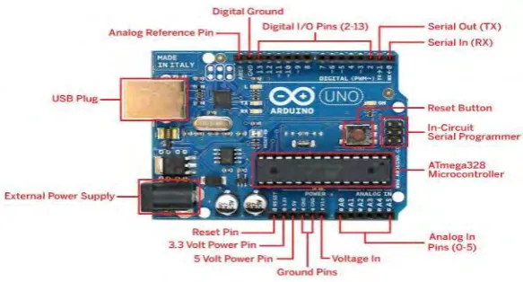
2.4.1.1 Arduino Platform
10 Arduino UNO
Figure 2.2: The pin of Arduino UNO Board (Tom Igoe, 2014)