White Rose Research Online URL for this paper:
http://eprints.whiterose.ac.uk/124729/
Version: Accepted Version
Article:
Aitken, J. orcid.org/0000-0003-4204-4020, Shaukat, A., Cucco, E. et al. (7 more authors)
(2018) Autonomous nuclear waste management. IEEE Intelligent Systems. ISSN
1541-1672
https://doi.org/10.1109/MIS.2018.111144814
© 2018 IEEE. Personal use of this material is permitted. Permission from IEEE must be
obtained for all other users, including reprinting/ republishing this material for advertising or
promotional purposes, creating new collective works for resale or redistribution to servers
or lists, or reuse of any copyrighted components of this work in other works. Reproduced
in accordance with the publisher's self-archiving policy.
[email protected] https://eprints.whiterose.ac.uk/
Reuse
Unless indicated otherwise, fulltext items are protected by copyright with all rights reserved. The copyright exception in section 29 of the Copyright, Designs and Patents Act 1988 allows the making of a single copy solely for the purpose of non-commercial research or private study within the limits of fair dealing. The publisher or other rights-holder may allow further reproduction and re-use of this version - refer to the White Rose Research Online record for this item. Where records identify the publisher as the copyright holder, users can verify any specific terms of use on the publisher’s website.
Takedown
If you consider content in White Rose Research Online to be in breach of UK law, please notify us by
Autonomous Nuclear Waste Management
Jonathan M. Aitken, Affan Shaukat, Elisa Cucco, Louise A. Dennis, Sandor M. Veres,
Yang Gao, Michael Fisher, Jeffrey A. Kuo, Thomas Robinson, Paul E. Mort
F
Abstract—Redundant and non-operational buildings at nuclear sites aredecommissioned over a period of time. The process involves de-molition of physical infrastructure resulting in large quantities of residual waste material. The resulting waste materials are packed into import containers to be delivered for post-processing, containing either sealed canisters or assortments of miscellaneous objects. At present post-processing does not happen within the United Kingdom. Sellafield Ltd. and National Nuclear Laboratory are developing a process for future operation so that upon an initial inspection, imported waste materials undergo two stages of post-processing before being packed into export containers, namelysort and segregate orsort and disrupt. The post-processing facility will remotely treat and export a wide range of wastes before downstream encapsulation. Certain wastes require additional treatment, such as disruption, before export to ensure suitability for long-term disposal. This article focuses on the design, development, and demonstration of a reconfigurable rational agent-based robotic sys-tem that aims to highly automate these processes removing the need for close human supervision. The proposed system is being demon-strated through a downsized, lab-based setup incorporating a small-scale robotic arm, a time-of-flight camera, and high-level rational agent-based decision making and control framework.
1
I
NTRODUCTIONA
N Autonomous System is one capable of making de-cisions for itself, at the time it chooses, without direct human intervention. Such systems are increasingly popular, especially indangerousorhostileenvironments that are haz-ardous for humans. In industrial processes, this adds the complication that humans monitoring the activity could bephysically remotefrom the working area or controlling alarge number of robots. Autonomous systems are increasingly popular for performingmundane and repetitivework where humans could rapidly become disinterested, and make mis-takes, especially if they were performing the repetitive tasks for several hours.
We describe the development of a system capable of assisting in autonomous nuclear waste management. This application scenario encompasses tasks that are dangerous and mundane. In the application for post-processing nu-clear waste a human operator cannot be nearby due to the radiation hazard. The nature of decommissioning and the size of the plants, with complex components, dictate perma-nent vigilance to ensure highly hazardous materials are not misclassified. Crucially, our autonomous demonstrator also contains fault tolerance and reconfigurability throughout the system to allow for fallibility [1]. The architecture for this reconfiguration, revolves around a vision system to sense the environment, a rational agent to take understandable
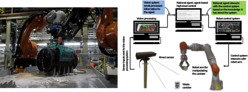
decision and a control system to enact them, summarised in Fig. 1.
At present no post-processing occurs within the United Kingdom. Sellafield Ltd. and National Nuclear Labora-tory are currently investigating methods to facilitate post-processing. A key component of these methods is the long-term operation of robots, which would be autonomous for the majority of tasks. Early generations of these systems will be teleoperated ensuring that workers need not enter haz-ardous environments [2]. Such systems will be complex to operate, and require intensive human supervision. This pa-per considers the essential step of coupling autonomy into this process, and its contribution lies in showing deploy-able architectures reducing the human operation of these robotic systems in hazardous environments. The method-ological novelty lies in our unique and effective merging of belief-desire-intention decision making with feedback control modules and computer vision to build an intelligent system for autonomous operations.
Development of an autonomous system capable of car-rying out this kind of complex manipulation requires sev-eral components. Firstly, vision sensing must be adequate for such a challenging environment. Ultimately the system must be in place for years. This means that the damage and degradation of the vision system must be expected during in-lifetime use, and adequate provision made before it can go live. The vision system will have to cope with presented objects that range in size and are inconsistent in shape. They will have been in operation for long periods of time, and will not look “as new”, for example discolouration or changes in shape which present novel challenges to the computer vision techniques.
which need not “know” the specifics of the components connected, just that appropriate actions can be performed.
2
U
SEC
ASE: P
OSTP
ROCESSING OFN
UCLEARD
ECOMMISSIONINGW
ASTENuclear plant decommissioning involves dismantling and removing either part or all of the plant infrastructure, and the process of decontamination (which may happen in stages, in the plant, and after dismantling in the remaining facility). At present post-processing of decommissioning waste does not happen in the United Kingdom. The Box Encapsulation Plant (BEP) currently being developed by Sellafield Ltd. and the National Nuclear Laboratory, will be the first facility dedicated to performing post-processing of decommissioning waste.
This process produces different types of solid waste material, which consists of hardware components and build-ing material together with long-lived activation products such as, gloves, glass, hand tools and sludges, whereas the
decontaminationprocess mostly results in liquid waste, such as chemical solutions and contaminated oils. It is important that all types of waste material are disposed of safely for the protection of the workforce, public and environment.
Post-processing offers clear benefits within the industry:
• Reduces the classification of waste; it can be sepa-rated into grade classes and dealt with accordingly, which saves money on overall storage costs.
• Reduces the final waste volume via better packing. • Produces safer waste packages by eliminating
voidages and releasing contained liquor. Voidages and liquor adversely affect container integrity if packaged incorrectly.
• Allows for the creation of a waste inventory which provides a record for regulation.
Autonomy within the process improves on teleoperation by increasing productivity and provides safer, more reliable operations that have the potential for continuous operation.
2.1 Waste Treatment Process
Nuclear waste disposal and storage involves a number of important processes. It begins with the delivery of the import container, containing an assortment of nuclear waste material, to the waste treatment cell. The inventory of the import container may not be known in advance and any records may be incomplete. Only certain wastes are defined as Waste Requiring Additional Treatment (WRAT). WRATs are characterised by a range of properties such as their physical state, handling difficulty, radiological or chemical content. WRATs undergo treatment that may include dis-ruption, size reduction, compaction or drilling before being placed into the export liner. Waste not requiring treatment is placed directly into the export liner.
National Nuclear Laboratory manages and runs the BEP development rig at their Workington facility for post-processing using tele-operated industrial Kuka KR500 robotic arms (see Fig. 1), once the development work is completed, the BEP facility will be owned and operated by
expected to classify waste types and predict their spatial ori-entation and proximity to the surrounding areas or objects. There should be a robust process used to select appropriate tools for processing each waste item, such as lifting it from the import container and placing it onto V-blocks on the waste handling table, while avoiding any collision or dam-age to surrounding areas. This also applies to the disruption process and other treatments for WRATs. A knowledge-based disruption decision needs to be made using available data, such as physical attributes of the waste item or vision and audio-based data collected during materials handling. Once the start and end points of the disruption process have been defined, verification should be carried out to identify a successful disruption has been performed.
Once the disruption process has been verified, rational decisions need to be made relating to the segregation pro-cedure (if required), space management in the export con-tainer, selection of appropriate hardware tools for handling, spatial orientation of the waste for packaging, multiple tools handling requirements, and residual debris management on the waste handling table. Once a set of satisfactory tasks have been completed, the cycle repeats for the next waste item or canister.
2.2 Autonomous Robotic Waste Treatment System
In this article, a rational-agent based distributed robotic sys-tem is presented in a reconfigurable framework (Fig. 1) that may potentially automate much of the BEP process. This will increase productivity whilst significantly reducing man-ual labour required as well as the related health and safety risks. A proof-of-concept small-scale end-to-end system is presented that closely replicates the BEP infrastructure with a few modifications in terms of hardware, requirements specification, and operational protocols, while still allowing maximum conformity with the real-world facility.
The demonstrator system has been developed and tested at Sheffield Robotics’ Laboratory using a KUKA iiwa arm. Referring to the system diagram in Fig. 1, the system uses a vision system, which takes inputs from a Time-of-Flight (TOF) camera. This is in contrast to BEP’s surround dome cameras used by the human operators. In our proposed system a rational agent replaces high-level human decision making, and has decisions enacted by a KUKA KR180 industrial-grade robot used in the developmental version of the demonstrator BEP test facility (i.e. non-active) being developed at National Nuclear Laboratory’s Workington site. The KUKA iiwa and KR180 provide a proof-of-concept for post-processing and training operators. Finally it can be scaled to the KR500 arms for deployment. The operational requirements and tasks for the laboratory-based demonstra-tion have been set as follows:
• Visual object detection, recognition, localisation of canisters (similar to the ones used in BEP, but smaller in size), and estimation of 6 DOF pose and geometric properties (such as length, radius, etc).
Fig. 1: Box Encapsulation Plant (BEP) KUKA robot trials at National Nuclear Laboratory, Workington, UK (left) and Proposed rational agent-based robotic system for autonomous nuclear waste management (right).
for disruption, post-disruption task allocation and monitoring).
• The robot arm performs the waste manipulation and disruption upon request from the rational agent. • The system can autonomously perform software
reconfiguration at different levels of abstraction -the current demonstrator has been limited to tool changes under failure conditions, hardware tools for cutting are emulated using multiple laser pointers.
3
V
ISIONP
ROCESSINGThe vision system uses a TOF camera to identify cylindrical objects in the scene, and predict their geometric properties, such as size and six degrees of freedom (DOF) pose estima-tion. It comprises a cascade of multiple processing blocks for 3-D object detection, recognition, and pose estimation using point cloud data as shown in Fig. 2.
An initial pre-processing filter is applied to the input point cloud to perform single dimension filtering to remove depth values that are outside a defined range. The filtered point cloud is used for segmenting the foreground objects from the background (e.g. the table surface) and eliminating residual outliers. The first step involves the use ofRANdom SAmple Consensus(RANSAC) to estimate a planar segmen-tation model for the filtered point cloud [3]. The RANSAC algorithm iteratively estimates the parameters of a math-ematical model defined for 3-D plane segmentation. The model coefficients are defined in terms of the (normalised) X,Y,Z coordinates of the plane’s normal and theHessian
component of the plane’s equation. An additional surface normal constraint based on the angular deviation between the plane’s normal and the inlier points is applied in ad-dition to the RANSAC “distance to model” criterion [3]. Surface normals are calculated for selected points in the input point cloud dataset representing important properties of the surface by calculating the K nearest neighbours of the query point which are searched using the K-d tree technique [3] within a specified spherical boundary. These points are used to estimate a local feature representation describing the geometry of the underlying surface.
Following the detection of the plane background, a 2-D convex hull polygon is constructed for the planar in-liers, which delineates the planar inliers within the waste handling table and objects that require processing (such as the waste canisters) from the surrounding outliers that may result in false positives (e.g. tools, random debris etc.). The resulting point cloud now consists of the planar inliers and the foreground objects.
Planar inliers from the resulting point cloud are filtered in order to segment foreground objects. A Euclidean cluster extraction technique is used to extract clusters from the point cloud that represents the foreground objects. Data clustering is carried out by subdividing the search space into a 3-D grid with fixed width boxes such as an octree data structure [3]. Each cluster represents a distinct foreground object. To detect and recognise canisters, an M-estimator Sample and Consensus (MSAC) [4] is used to define and estimate a model for 3-D cylinder segmentation. The model coefficients are defined byX,Y andZcoordinates of a point located on the detected cylindrical object’s axis, the axis direction and the cylinder radius. Detected canisters and their geometric properties along with their pose estimates are sent to the rational agent.
4
T
HER
ATIONALA
GENTA key aspect of any autonomous system is that software must make decisions rather than the human controller. This necessitates an architecture of control and decision making that captures what actions the system does, what choices it makes that led to its actions and why it made one choice rather than another [1]. A hybrid form of architecture allows us to separate and analyse (discrete) decision-making aspects from robotic (continuous) control aspects [5].
information provided by sensors and some world model. A decision, in this context, means selecting a necessary plan for execution from a plan library and instantiating it.
Autonomous systems may also need to self-reconfigure to cope with changes, either in subsystems or in the envi-ronment, especially if the system is to be used in areas that are dangerous or that cannot be entered by humans. There-fore the reconfiguration process is required to change the internal architecture of the system or the form of the control systems in order to satisfy the changing environment, or to adapt to failure or damages of some of the subsystems in a way that it can still continue to achieve some or all of its goals. For instance, if the agent realises that an action cannot be performed successfully with a particular tool then it must instruct the robot to use better performing hardware for that action, or if one camera provides errors the agent can ignore the data coming from this camera and use another one, in order to improve information about the environment.
If something changes during the execution, the agent may need to perform additional reasoning to reconfigure the system architecture. If hardware fails, or is added, the agent needs to modify (or reconfigure) the control system and/or its high-level goal/plan selection to take into account re-stricted or new possibilities. Changes in the controller may be caused by various factors, e.g. unanticipated errors or newly found controllers with superior performance.
Another aspect of reconfigurability is where the hard-ware and control aspects of the system remain the same, yet the agent itself reconfigures high-level elements, such as goals, plans, knowledge, and potentially strategies. This can occur if new information or capabilities become available.
4.1 Agent architecture
We employ a hybrid agent architecture summarised in Fig. 2. The main problem when connecting continuous control systems to a discrete entity, such as our agent, is that the continuous stream of data coming from the sensors has to be converted into discrete values that the agent can reason about. For this reason our agent’s architecture introduces an “abstraction engine”, sitting between the reasoning engine (the agent) and the rest of the system. This abstraction engine provides the continuous-to-discrete translation, taking streams of data from the sub-symbolic subsystems and passing on discrete abstractions of this to the agent itself. In the other direction, the abstraction engine is responsible for translating all the discrete decisions and instructions coming from the agent into proper commands for the control subsystems (see Fig. 2).
All the information that needs to be shared between the agent and the control systems to allow their collaboration are stored in the knowledge base (or world model), which is itself divided in three different sections:
• Perception; describing information about the world. • Configuration; describing the existing components in
the system and their capabilities.
• “Program data”; storing all the models, route plans, maps, metrics, and all the data that must be shared by all the components in the system.
edge base is managed via two mechanisms. The agent can register an interest in particular issues and will be notified on a “push” basis whenever those issues change. Furthermore, it can directly query the knowledge base for additional information. Thus, the agent is not over-loaded with information about every change that occurs in the knowledge base, but can still access any information it needs and learn items of critical importance as soon as possible.
The agent approach we used has been encapsulated within the BDI model [6] where BDI stands for beliefs, desires and intentions. Beliefs represent the agent’s view about the environment and itself; desires represent the ob-jectives to be accomplished; intentions are the set of tasks currently undertaken by the agent to achieve its desires. A BDI-style agent has a set of plans, determining how an agent acts based on its beliefs and goals, and an event queue where event are stored. One of the advantages in using this style of model for developing autonomous systems is the incremental and hierarchical development of plans.
4.2 Implementation
TheAbstraction EngineandReasoning Engineare both imple-mented using theJava-based Gwendolen agent
program-ming language [7], that ships with the Agent Infrastructure Layer, supporting the implementation and verification of BDI programming languages [5]. Requests for calculations or actions from the Reasoning Engine are read into the Abstraction Engine as perform goals. The communication between the Java process and the Physical Engine is via
ROS (Robot Operating System) messages and exists within aJava“Environment” layer. Gwendolen plans consist of:
• atrigger— typically the addition of a goal or a belief; • aguard— typically all the agent’s beliefs which must
be true to allow the execution of the plan; and • thebodycomprising a stack of ‘deeds’ that the agent
executes in order.
Essentially, the agent chooses the action to be performed according to its beliefs and the goals, and it will send an instruction to the robot and then will wait for a belief (com-munication from the robot arm) that indicates this action has been completed. Afterwards this belief will be removed so it does not interfere with the future performance of the same action for another object. The whole process is shown in Fig. 2, where the“done”link represents the feedback from the robot after an action is completed.
For our nuclear demonstrator, the disruption process has been simulated using laser pointers, and in order to assess the efficiency of the cutting tool, the agent will assess information coming from the vision system. If the information differs from what is expected, the rational agent will consider the disruption process unsuccessful and will ask the robot arm to try again with a different tool.
Fig. 2: Architecture of an hybrid agent system (right), agent rules (left) and proposed machine vision system (bottom).
communications layer that allows interaction between in-dividual processes [8]. This can typically be visualised as a tri-partite graph which consists of individual processing components calledNodes, communicating throughMessages
either broadcast to any other Nodessubscribed overTopics
or through individual requests and responses established when required throughServices.
A traditional feedback control system is made of sensors which measure the physical environment, actuators which bring about some physical change, and a control system which requests movement of the actuators to bring about a desired state, measured through feedback. These compo-nents can be mapped to ROS compocompo-nents. Providing each individual block produces outputs and receives inputs of the correct form, then these blocks can be switched in plug and play control [9]. This can be achieved by monitoring theFunctional Dependencyof modules so that reconfiguration can be autonomously triggered to develop control systems that satisfy specific problems [10].
This functional dependency can be represented as a lightweight representation of component capability. Any component that offers a capability can be substituted provided consistency of data-types and communication medium is preserved. This enables each component to have an agnostic connection defined by capability rather than de-vice. This enables capability to be abstracted, and separated from component and exacting method. Consider the case where a rational agent is capable of moving a robot arm from one position in space to another - a truly reconfigurable
system should not be concerned with the manufacturer or interface to the arm; its consideration is the capability of movement not the exact implementation. Within ROS the interface and device can be abstracted to allow connection to this capability, as has been demonstrated in the practical implementation.
5.1 Control System Design
The full control system has been developed within ROS in order to interface neatly with the vision and agent-based sub-systems discussed previously. This controller is split into a two-tiered architecture, the higher level contains an overall controller that provides an interface to the vision system and agent. The lower level contains two independent controllers, which operate a Schunk dextrous gripper and KUKA iiwa arm. As the gripper and arm are two separate units, from independent manufacturers, their controllers are kept separate to allow interoperability in future scenarios.
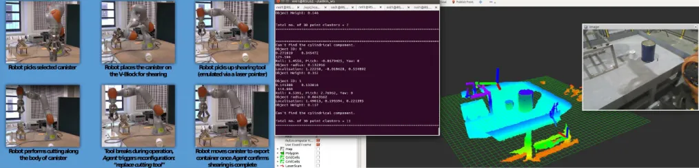
Fig. 3: Video Capture of Full Demonstrator Process (left) and sample of vision system operational within test rig at National Nuclear Laboratory, Workington, UK. (right).
Reconfiguration to operate on the KRC4 of the Kuka KR180 becomes the simple task of replacing the communi-cation components, maintaining the functional dependency and capability whilst modifying the underlying control code but maintaining independence from the rational agent. In this case the architectures and communication protocol for each robot arm are different, the KRC4 uses the KUKA Robot Language (KRL) whilst the KUKA Sunrise uses Java. Therefore the interface, agent logic and vision systems are isolated from platform change.
5.2 Full Demonstrator
The demonstrator outlined in Section 2.2 has been im-plemented, coupling a vision system, rational agent, and robotic arm1. This produces a demonstrator simulating au-tonomous waste processing of materials realised as a dis-tributed system using ROS. Fig. 3 shows a series of images from a video sequence of the system in operation.
6
C
ONCLUSION ANDF
UTUREW
ORKThis paper demonstrates a system simulating autonomous processing of nuclear waste materials that has been devel-oped as part of the Reconfigurable Autonomy [1] research project. The nature of this task demands that an autonomous system is deployed, as it must operate for long periods of time performing an operation that is both repetitive and dangerous for a human. This has been implemented using a hybrid-agent architecture comprising three separate components: a vision system; a rational software agent; and a flexible control system. A complete end-to-end system has been produced using a KUKA iiwa next-generation robotic arm, Microsoft Kinect, and rational agent implemented in the Gwendolen programming language. This system is ca-pable of performing fully autonomous waste processing for undefined canisters that are continuously and randomly presented. Straightforward reconfigurability is provided via plug-and-play module switching which allows easy trans-fer to the industrial plant. The rational agent encapsulates limited self-awareness and can undertake more complex re-configurability required in the face of degrading behaviours. We continue to work with Sellafield Ltd. and National Nuclear Laboratory to move this prototype towards prac-tical use in nuclear scenarios. Fig. 3, presents a sample of
1. This video will be made available online upon paper acceptance.
the inactive rig onto which this system will be deployed, with the vision system operational. To broaden applicability to a wider range of nuclear materials the vision system, the rational agent, and the gripper control must all learn to cope with different objects, materials, and processing strategies. Finally, the use of the rational agent provides the possibility of scrutability and verifiability.
A
CKNOWLEDGMENTSThe National Nuclear Laboratory is owned and operated by the UK government and provides nuclear services tech-nology that covers the whole of the nuclear fuel cycle. The Sellafield nuclear site is the UK’s largest and most complex nuclear facility. The authors would like to thank them for their invaluable assistance in providing access to their facilities in order to gain first-hand knowledge of the requirements and engineering constraints that played a crucial role in the design of the proposed system.
This work was supported by the Engineering and Phys-ical Sciences Research Council under Grants EP/J011916, EP/J011770, and EP/J011843.
R
EFERENCES[1] L. A. Dennis, M. Fisher, J. M. Aitken, S. M. Veres, Y. Gao, A. Shaukat, and G. Burroughes, “Reconfigurable autonomy,” KI-K ¨unstliche Intelligenz, vol. 28, no. 3, pp. 199–207, 2014.
[2] M. Talha, E. Ghalamzan, C. Takahashi, J. Kuo, W. Ingamells, and R. Stolkin, “Towards robotic decommissioning of legacy nuclear plant: Results of human-factors experiments with tele-robotic manipulation, and a discussion of challenges and approaches for decommissioning,” inIEEE International Symposium on Safety, Security, and Rescue Robotics, 2016, pp. 166–173.
[3] A. Aldoma, Z.-C. Marton, F. Tombari, W. Wohlkinger, C. Potthast, B. Zeisl, R. Rusu, S. Gedikli, and M. Vincze, “Tutorial: Point cloud library: Three-dimensional object recognition and 6 DOF pose estimation,”IEEE Robotics Automation Magazine, vol. 19, no. 3, pp. 80–91, Sept 2012.
[4] P. Torr and A. Zisserman, “MLESAC: A new robust estimator with application to estimating image geometry,”Computer Vision and Image Understanding, vol. 78, no. 1, pp. 138 – 156, 2000.
[5] M. Fisher, L. A. Dennis, and M. Webster, “Verifying Autonomous Systems,”ACM Communications, vol. 56, no. 9, pp. 84–93, 2013. [6] A. S. Rao and M. P. Georgeff, “An abstract architecture for rational
agents,” in Principles of Knowledge Representation and Reasoning, 1992, pp. 439–449.
[8] M. Quigley, B. Gerkey, K. Conley, J. Faust, T. Foote, J. Leibs, E. Berger, R. Wheeler, and A. Ng, “ROS: An Open-Source Robot Operating System,” in ICRA Workshop on Open Source Software, 2009.
[9] J. Bendtsen, K. Trangbaek, and J. Stoustrup, “Plug-and-Play Con-trol - Modifying ConCon-trol Systems Online,” IEEE Transactions on Control Systems Technology, vol. 21, no. 1, pp. 79–93, 2013. [10] J. M. Aitken, S. M. Veres, and M. Judge, “Adaptation of system