SIMULATION AND BIM FOR BUILDING DESIGN, COMMISSIONING AND
OPERATION: A COMPARISON WITH THE MICROELECTRONICS INDUSTRY
Paul Tuohy
Energy Systems Research Unit, University of Strathclyde, Glasgow, Scotland
ABSTRACT
Analogy between the Microelectronics and Building industries is explored with the focus on design, commissioning and operation processes. Some issues found in the realisation of low energy buildings are highlighted and techniques gleaned from microelectronics proposed as possible solutions. Opportunities identified include: adoption of a more integrated process, use of standard cells, inclusion of controls and operational code in the design, generation of building commissioning tests from simulation, generation of building operational control code (including self-test) from simulation, inclusion of variation and uncertainties in the design process, use of quality processes such as indices to represent design robustness and formal continuous improvement methods.
The possible integration of these techniques within a building information model (BIM) flow is discussed and some examples of enabling technologies given.
INTRODUCTION
The microelectronic systems embedded in a silicon chip are highly complex. A typical microcontroller chip has several hundred analogue and digital inputs and outputs and many modules with specific functions such as processors, timers, communications, signal processors, monitors, or alarms and may be used in critical applications in dynamically variable environments such as in automotive or aeronautic industries. Energy consumption of microcontrollers is often highly critical for battery sensitive applications such as automotive, military, space, mobile computing and communications.
The challenge facing designers of automotive micro-electronic systems can be compared to the challenge of realising a complex building. In both cases the system must maintain comfortable and safe conditions, operate and monitor plant, respond to variations in occupant behaviour, internal and external environments, while minimising energy use and emissions.
Both systems are required to accept changes in settings from the user and display performance parameters and alarms, detect and take appropriate
actions for different modes of operation (accelerating, braking c.f heating, cooling etc) and respond appropriately in fault conditions. Figure 1 illustrates in simple terms the key elements of the automotive system. There are sufficient similarities with building systems to make comparison worthwhile.
Air Fuel Exhaust
Temp. Speed, Pressure uControl dash
pedals indoor
environment outdoor environment environment comfort
safety
wheel
traction speed pressure economy
[image:1.612.318.520.291.438.2]emissions surfaceslope battery
Figure 1 The Automotive Environment
The semiconductor design methodology is highly integrated and automated. At the earliest design phase the systems functionality is described in a very high level behavioural language (e.g. VHDL) where functional blocks and their key parameters are specified. VHDL was developed as a standard by the US Department of Defense in the 1980’s in order to be able to comprehend and integrate complex systems; VHDL allowed behaviour to be comprehended more easily than through the complex detailed manuals typical at that time. Tools were quickly developed to simulate the high level behavioural descriptions and synthesise the high level behaviour into hardware specifications for implementation. Librarys of model sets are available to represent different possible hardware types and their associated performance variations. To reduce the overheads and cycle time in producing new designs, standard cell libraries are established where well characterised components which have been fully verified are stored for re-use.
Microelectronic systems are highly simulated before the expensive tools used to fabricate them are ordered. The simulation testing includes the operational code, has a high level of fault coverage (i.e. high ratio of faults that will be detected by simulation against the total number of possible faults) and includes the likely variations in performance due to uncertainty in the fabrication processes and likely ranges in operating and environmental conditions (Tuohy et al, 1987). The robustness of the design may be quantified using a ‘six-sigma’ capability index (Pryzdek, 2003). Robustness is defined here as the ability of the system to perform correctly across the range of future uses and future environments that may occur during its lifetime. The six-sigma quality methods used by the microelectronics manufacturers are also imposed on the suppliers of the equipment and materials used in the fabrication and testing phases.
Test code is generated from the simulation software with a high fault coverage and then used used to evaluate the system once built using automated test equipment.
The test flow often includes specific tests designed to weed out subtle or latent defects which would become early-life failures, tests may include stressing the system in a controlled manner (typically beyond specification limits) for short periods and / or measuring background ‘quiescent’ power consumption with the chip in defined modes. The operation control code developed in the simulation is used as the actual operation code and embedded in the system. The operation code often includes a Built In Self Test (BIST) function allowing automatic detection of system malfunction when in operation.
Throughout the design and test processes possible failure modes are analysed and assigned a risk level
based on likelyhood of occurrence, probability of detection and severity of impact (known as fail mode effect analysis or FMEA). Actions are then taken to pro-actively ensure the risk levels are managed i.e. reduced or eliminated so that they should not occur in practice. FMEA’s from one project form the starting point of the FMEA of the next ensuring that learnings are transferred.
Where issues do occur then a rigerous 8 step methodology is used to problem solve (known as 8-D). This involves problem root cause and fix identification but also looks at the systemic reasons that the problem occurred (i.e. why not anticipated and avoided through the FMEA process) and ensures that the processes are improved and the FMEA updated to ensure that there can be no recurrence in the current or in future projects.
The microelectronics realisation process initially benefited from a high level of integration however recently microelectronics has become fragmented with the move to low cost sub-contractors. Strong processes have enabled this fragmentation to be achieved successfully.
Recent developments in the buildings industry and the associated legislation are moving towards a more automated and integrated approach. The recognition of building simulation in recent legislation leading to more widespread adoption as well as the ongoing development and increasing adoption of the Building Information Management (BIM) methodology (including adoption by the US Army (Succor, 2009)) are steps in this direction. This more integrated and automated approach then provides a platform for the possible adoption of appropriate elements of the process used in microelectronics. This paper explores this possibility in more detail.
DEFINITIONS
Some key definitions:
VHDL: High level design language allowing a design to be described based on behavioural description of component parts.
Standard Cell Library: Library of previously validated designs and component parts.
Six Sigma: A Quality Process which aims to achieve less than 3.4 defects per million, applied across the project including contractors and suppliers.
Robustness: The capability of a design to function correctly over all likely future environmental and operating conditions.
BIST: Built in Self Test; tests for detection of errors in operation, built into the operating software. Stress Tests: Test that go beyond normal specifications in order to identify areas of weakness. Quiescent Tests: Tests which put a system into a defined mode and check for any un-intended energy use which would indicate a fault.
8-D: An 8 step problem solving methodology for dealing with issues and ensuring they don’t re-occur. Quality Reporting: Public domain ranking of companies performance in league tables for criteria including quality, defect rates, reliability, energy performance, on-time delivery etc.
PROBLEMS WITH THE CURRENT
BUILDING REALISATION PROCESS
This section highlights through examples some problems seen commonly in buildings intended to be low energy and implemented using current design practices. Four cases are given below which have been selected to illustrate the issues and then a summary is formed
Case 1: BRE Environmental building.
The BRE Environmental building was completed in 1996 and is a naturally ventilated office building over three floors situated in Garston, England. The design intent was to achieve similar environmental control as an equivalent air conditioned building but with energy use no higher than an equivalent naturally ventilated building. Key features of the building include high thermal mass, multiple BEMs controlled ventilation modes, solar chimneys, occupant open-able windows, night cooling, solar shading, low energy daylight responsive lighting, under-floor heating and groundwater under-floor cooling. The building was monitored after completion and found to perform very well for occupant satisfaction and energy use compared to other office buildings of the time. Although the energy use in operation was reported to be around 20% above the design target, it was suggested that the difference was due to higher levels of computer use than planned.
An exercise was undertaken in 2005 and 2006 to revisit the building, review its performance and identify opportunities where further improvements could be made. The approach taken was to gather design data, BEMs manual, monitoring data, obtain access the BEMs system, carry out a survey of the building, build a simulation model of the building, compare the virtual building performance to the actual building performance, develop improvement strategies using the virtual building, validate and implement on the actual building while continuously monitoring energy use and comfort. There were significant learning points which when acted on will allow reductions in energy use and increases in occupant comfort, these should be viewed as further
improvements to this exemplar building which has been operating successfully for over 10 years. Key findings from this exercise were as follows: 1. The controls documentation was poor and not well understood by occupants, building managers or controls sub-contractors leading to changes to fix issues that then caused other issues.
2. The control implementation was based on a concept design document provided by the architects. 3. The control strategy as implemented was not optimum from an energy consumption viewpoint e.g. mechanical borehole cooling was being applied at a lower temperature threshold than free cooling by window opening.
4. The control strategy did not include response parameters appropriate to the slow response heavy mass heating and cooling elements which reduced control effectiveness.
5. The control system was too simplistic e.g. night cooling mode was triggered by external conditions at 4pm only. Afternoon rainfall could mean that night cooling would not be triggered despite extremely high internal temperatures and overall high external temperatures.
6. Incorrectly implemented controls of bore-hole cooling led to incorrect operation. It was observed that the response of the building to borehole cooling commencement was not as expected from simulation. Analysis of the hardware showed that a temperature compensation valve for winter heating was still active in the summer cooling mode leading to the cooling water being heated to the compensated heating temperature of around 25 degrees rather than flowing at the design value of 16 degrees. Interrogation of the BEMs confirmed this erroneous operation had been occuring since the building was constructed.
7. Fault conditions were not optimum. It was observed that pumps were running and gas being used when there should have been no demand for heating. It was found that a spurious fault condition had caused the non condensing boiler and the hot water feeder circuit to fire indefinitely.
8. Building performance and energy use was not generally visible. There was no display other than on the BEMs PC (inside a locked control room). Implementation of improvements is now under-way.
Case 2: S.N.H. headquarters building
heating and occupant open-able windows. Many features are similar to the BRE Environmental building. At the time of the investigation the building was going through the initial commissioning and ‘snagging’ process. Key findings were as follows: 1. There was great pressure to complete and sign-off the commissioning so that financial milestones could be met and penalty charges avoided. Many of the project team from the design and build phases were no longer formally involved once sign-off complete. 2. There was poor visibility at this time for the operations staff and the occupants of the energy design targets and the actual energy use for each of the sub-meters provided throughout the building. 3. The control strategy was documented in a comprehensive but complex operations manual and was not clear to operations staff and occupants. 4. The commissioning engineers were working to the control strategy developed during the concept design stage which gave somewhat coarse step function control e.g. “when temperature rises above set-point open both the high level office and the atrium windows” which would activate all high level windows on all three floors together with the atrium opening at the same instant. The control strategy did not take into account wind direction and speed in detail in the calculation of window open extents. 5. There was debate as to what areas the design targets should apply to and whether areas such as server rooms were to be included in office specifications etc.
6. The BREEAM and best practice guides stated that seasonal commissioning should take place but there was at that time no plan in detail for how this would be approached.
7. The operations staff responded to occupant feedback by altering set-points to fix immediate issues without necessarily comprehending the impact of these changes on the overall control strategy and building performance at other times of the year etc. 8. The heating control was achieved through occupant adjustable thermostatic radiator valves on radiators under the open-able windows with no zone thermostats. The heating system had a ‘hold off’ external temperature set-point but otherwise no difference between summer and winter heating control.
Case 3: German low energy office study.
German Federal Ministry for Economy demonstration program covers 22 non-actively cooled buildings, the program has been running since 1995 and involved monitoring energy use, environmental conditions, occupant behavior and comfort. An observation was that the monitoring and high focus on these buildings highlighted many system operation errors similar to those seen in the BRE Environmental office case and they draw the conclusion that these types of problems are common
practice in the building stock: “In many cases, detailed analysis of the electricity consumption helped to identify weaknesses in the system operation and aid their correction: operation of the heating system pumps outside the heating season, heating of pre-cooled air by an earth-to-air heat exchanger during summer, etc. In large buildings operational faults cause energy consumptions and energy costs in an order of magnitude which is not negligible. From the experiences it can be assumed that these kinds of faults are common practise in the operation of the building stock as a whole.” (Voss et al, 2007).
Case 4: London City Hall.
London City Hall is an iconic local Government building completed in 2002 on the banks of the river Thames close to Tower Bridge. It was designed and is still promoted as ‘sustainable and virtually non polluting’.
The buildings energy performance has been monitored and it used 376kWh/m2 in 2003/2004 compared to its design target of 236kWh/m2 (Bennet, 2005) with the discrepency stated as being primarily due to being occupied by 650 people rather than the 440 person occupancy designed for. The poor energy performance has resulted in the building being awarded an ‘E’ rating under the EU Energy Performance of Buildings Directive (Booth, 2008). There have been complaints aired in national media such as the building being too warm or too humid in the summer, occupants experiencing sudden chills in winter and windows opening automatically allowing rain into the building.
Summary of the problems.
The design, construction, commission and operation process as currently applied has a number of issues which can result in the performance of the building being poorer than expected in terms of either comfort or energy use.
The participants in different stages of the process are not consistent and there are contractual and financial milestones in the project which act to partition the project and act against synergy throughout. These contractual and financial milestones also act to put great pressure on the later process steps so that often commissioning is carried out in an extremely stressful environment in the face of financial penalty clauses if project timelines are not achieved. There is no Quality Process established and contracted into by the project participants.
conditions that will be prevalent over the lifetime of the completed building. The detailed design phase typically does not include design and validation of controls use by occupants or the operation code for the BEMs system where this is to be installed. Simulation, where carried out is not applied consistently and the extent to which the building design is excercised in simulation is not quantified. Errors occuring during the construction and system installation phases are common, possibly arising due to poor understanding, lack of detailed specifications or lack of a quality system.
Generally components are installed and tested to a standard set of the manufacturer’s routines which may not well represent their intended operation in the specific building.
The commissioning phase of the project is often the last step before a major financial milestone and will often be attempted in a compressed timescale in order to recover slips elsewhere in the schedule. The controls engineer receives only the simplistic conceptual design description of the required operation and translates this in to operational BEMs code based on his best judgement. Because the controls are based on the conceptual rather than detailed design then often these are too course and simplistic for actual operation leading to step function changes in conditions and discomfort. The commissioning process typically exercises the controls and confirms that sensors, set-points and actuators are connected and operational but does not normally fully exercise building responses (time constants, weather compensation etc.), integrated control strategy or fault conditions. The commissioning testing quality and fault coverage is not quantified and often faults are not found.
The commissioning phase often provides the person responsible for the operation of the building with a thick manual and access to a number of BEMs screens on which set-points may be adjusted but not necessarily a good understanding of the operational strategy, current energy performance or design targets.
Seasonal commissioning is now a specified requirement (CIBSE, 2006) however the process to be used, especially for naturally ventilated or hybrid buildings, is not specified in detail and this often leads to a seasonal repeat of the basic exercise of the controls looking for any simple faults which have occurred plus a tweaking of the control set-points based on the feedback from the building occupants via the building operator without comprehending the effect this will have on other seasons etc.
In the operational phase the building operator is often initially bombarded with warnings and faults and can become desensitised. BEMs screens are often only visited in the case of serious complaints or equipment malfunctions. The energy used is often only monitored if at all through the financial billing from
the utilities which are often based on estimated rather than actual energy use.
The end result of the current process is that it is common for buildings to have significantly poorer energy and comfort performance than planned.
AN IMPROVED PROCESS?
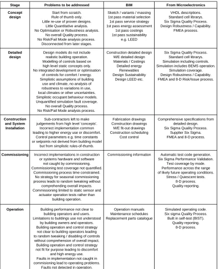
The approach to virtual prototyping and validation in the microelectronic industry appears more rigorous than is current in the buildings industry and it is possible to propose some improvements which may reduce occurrence of the issues identified in the previous section. It is suggested that the improvements could be implemented within a BIM framework. Figure 2 lists the main stages and functions within a typical BIM flow, the problems with current methods, and techniques from microelectronics that could be integrated to address these problems. Application of these techniques is discussed in more detail in the following sections and some examples given of current research that could be developed further to support implementation.
Concept design:
Selecting of the right design concept for a sustainable building requires consideration of many factors such as building form, building systems, future climates, occupant perceptions, comfort and behaviours, risks, costs, legislation etc. Decisions at the concept design stage can have the largest impact on actual building performance.
then be repeatedly manipulated and simulated to give rapid feedback on performance of options.
There are a number of current developments in building simulation that are aligned with this approach and could support its adoption.
The BIM approach and also the linking of tools such as Revit or Sketch-up with building energy simulation is providing a more accessible interface, a library of standard cells could certainly be included within this environment.
A standard cell approach is already being used to some extent in recent policy and regulatory tools. In the domestic arena the EDEM tool (Clarke, 2008) is based on an array of thermal simulation models which can be selected through determinant parameters and the results combined with system type, cost and carbon emissions information to provide instant feedback to enable upgrade strategy decisions. The EDEM-K (Ghauri et al, 2009) and ADEPT (Cockroft et al, 2007) tools go further in that they allow standard cells to be selected and if required their parameters can be customised and the modified models simulated real-time and the new results then used in the analysis. In the non-domestic arena, the implementation of the UK EPBD NCM method in simulation software has necessitated the implementation of standard libraries of construction types, activity types, system types and climates within the simulation tools. While these current initiatives have not yet been targeted at concept design they include some elements from which a concept design tool could be evolved.
The possibility of using a capability parameter to describe building robustness was recently explored in the context of naturally ventilated and hybrid building design (Tuohy, 2009, Tuohy et al, 2009). This work describes the incorporation of adaptive comfort, adaptive behaviour and other uncertainties such as internal gains and climates in a simulation method to give a capability parameter based on the six-sigma approach. This six-sigma capability parameter can be used to compare the robustness of different design options during the design phase and also subsequently be used to communicate to the building owner the limitations within which the building will operate successfully and outwith which some mitigation actions will have to be taken (i.e. if a building is not robust for high internal gains then the building owner should understand this and be aware of the need to reduce the gains, re-locate or upgrade the property appropriately).
Detailed design:
Although being improved in part through software accreditation requirements for energy rating, energy performance simulation in detailed design could, in addition to the areas discussed in the concept design section above, be improved by expansion of scope to include the modelling of systems and controls including building and system specific parameters,
fault detection and fault condition responses. Inclusion of controls in the simulation should allow the development of commissioning tests and the operational BEMs control code (including built-in self test functionality) and the validation of the operation of this code for variations in climate and building use including impacts on occupant comfort. The software used by BEMs manufacturers and controls companies to define their controls is not generally incorporated in the building energy simulation. There have been some recent developments within ENERGY+ (Ellis et al, 2007) but this functionality is not yet fully established. Simulation should be carried out with a quantified coverage and building performance robustness validated for a stated variation in input parameters. The range of building use parameters and climates over which performance robustness has been verified and therefore the limitations on the building should be clearly communicated to the building realisation team and made clear to the clients.
The FMEA should be used as a reference as simulation may be required to verify that an identified risk will not occur. Similarly when simulation identifies a new problem then 8-D methodology should be used and the FMEA updated for future use.
Construction and system installation:
Greater simulation coverage in the detailed design phase will allow more detailed specifications to be provided for construction and system installation. The quality system can be extended to the supply chain and form a common language for the team with FMEA review and 8-D used to avoid problems or resolve them when they occur and ensure action is taken to avoid re-occurrence in future in this or in other projects using the same realisation process.
Commissioning:
The generation of commissioning test code from the detailed design stage which will exercise the buildings systems and controls in various modes and with a defined high coverage of possible faults should be able to identify with a high level of confidence any implementation or design issues. The test code could be run through the BEMS system itself or through a specialised system (possible including the simulation model) interfaced to the BEMS.
In addition to excercising looking for ‘hard’ faults the commisioning could be developed to include stress tests and quiescent power tests which may also identify latent or marginal faults which would have failed in operation.
are not made on an ad-hoc basis but only after validating the changes in the model across seasonal climate and other variations and also understanding the root cause and ensuring the learnings are fed back into the design system and comprehended in future projects.
Operation:
The operational BEMS code should have been validated in the simulation model and include a built-in self test function (probably built-involvbuilt-ing quiescent power tests to check for unintended loads etc). Where faults occur they should be dealt with using the same quality system as used in the earlier phases and learnings fed back into the process.
During operation then energy performance, comfort and customer satisfaction should be monitored against the design targets and expected performance distribution and the information provided in a clear format to the building occupants and maintenance staff.
Ideally the performance against targets, customer satisfaction and failure rates would be publically available so the team who deliver the building are accountable for its performance. (Microelectronics customers regularly rate suppliers quality and results are published similar to car manufacturers rankings for reliability). The introduction of display energy certificates for public buildings in England is already achieving high media coverage.
DISCUSSION
The intent of this paper is to take a fresh look based on experience of another industry and put forward for discussion potential synergies that may provide potential solutions for some of the problems that exist in the current building realisation methods.
CONCLUSIONS
Analogy between the Microelectronics and Building industries has been explored with the focus on design, commissioning and operation processes. Some issues found in the realisation of low energy buildings are highlighted and techniques gleaned from microelectronics proposed as possible solutions. The cases reviewed include office buildings specifically designed to be low energy and highlight the difficulties being experienced in this area. Opportunities are proposed including: adoption of a more integrated realisation process; use of quality controlled standard cell libraries in concept and detailed design; integration of plant, control and operational code simulation in the design process; high fault coverage in simulation; automatic generation of building commissioning tests with high fault coverage from simulation; generation of building operation control code (including self-test) from simulation; inclusion of variation and uncertainties such as in building patterns of use, future climates etc. in the design process; use of
quality processes and indices such as six-sigma, FMEA and 8-D to comprehend the robustness of the design and continuously improve the integrity of the building realisation process.
The possible integration of these techniques within a building information model (BIM) flow is discussed and some examples of enabling technologies given.
REFERENCES
Clarke J A, Johnstone C M, Kim J M and Tuohy P G (2008) 'Energy, Carbon and Cost Performance of Building Stocks: Upgrade Analysis, Energy Labelling and National Policy Development', Chapter in Advances in Building Energy Research, ISBN: 978-1-84407-389-4.
Tuohy P, Gribben A, Walton A.J, Robertson J.M, 1987. Realistic worst-case parameters for circuit simulation. IEE Proceedings, vol. 134, no. 5, pp. 137-140, Oct. 1987.
Tuohy P, 2009. Regulations and Robust Low Carbon Buildings. Buildings Research and Information, (In Press, Accepted with minor modification) Tuohy P.G, Humphreys M.A, Nicol F.J, Rijal H.B,
Clarke J.A, 2009. Occupant behaviour in naturally ventilated and hybrid buildings. ASHRAE Transactions, Jan 2009 (Presented Chicago, transactions in process).
Pyzdek T. 2003. Quality Engineering Handbook, 2nd Edition, ISBN 0824746147
Voss K, Herkel S, Pfafferott J, Lohnert G, Wagner A, 2007. Energy efficient office buildings with passive cooling – Results and experiences from a research and demonstration programme. Solar Energy 81 (2007) 424–434
Ellis P.G, Torcellini P.A, Crawley D.B, 2007. SIMULATION OF ENERGY MANAGEMENT SYSTEMS IN ENERGYPLUS. Proceedings: Building Simulation 2007.
Succar B, 2009. Building information modelling framework: A research and delivery foundation for industry stakeholders. Automation in Construction, Volume 18, Issue 3, p. 357-375. Ghauri et al, 2009. EDEM-S. Submitted BS2009. Cockroft, J., Samuel, A., Tuohy, P. 2007.
Development of a Methodology for the Evaluation of Domestic Heating Controls. Phase 2 of a DEFRA Market Transformation Programme project, carried out under contract to BRE Environment. Available at http://www.sesg.strath.ac.uk/Downloads/Report_ BRE_E302_040707.pdf
Booth R, 2008. Halls of Shame: biggest CO2 offenders unveiled. The Guardian, 2 Oct, 2008.
Stage Problems to be addressed BIM From Microelectronics
Concept Start from scratch. Sketch / variants / massing VHDL descriptions.
design Rule of thumb only. 1st pass material selection Standard cell librarys.
Little re-use of proven designs. 1st pass service strategy Six Sigma Quality Process.
Little Quantitative analysis. 1st pass energy assessment Design Robustness / Capability.
No Optimisation or Robustness analysis. 1st pass costings FMEA process.
No overall Quality process. 1st pass sustainability
No Risk/Fail Mode analysis process. e.g. LEED
Disconnected from later stages.
Detailed Design models do not include Construction detailed design Six Sigma Quality Process.
design realistic building operation. M/E detailed design Standard cell librarys.
Modelling of controls based on Materials / Costings Simulation including controls.
high level static concepts only. Detailed energy Simulation includes BEMS operation.
No integrated development or optimisation Renewables Simulation coverage.
of controls for comfort / energy. Design Sustainability Design Robustness / Capability.
Simplistic assumptions of building Design LEED etc. FMEA and 8-D Risk/Issue process.
use and climate, no analysis of robustness to variations in use, local climates or other uncertainties. Simplistic occupant behaviour models. Unquantified simulation fault coverage.
No overall Quality process. No Risk/Fail Mode analysis process.
Construction Sub-contractors left to make Fabrication drawings Comprehensive specifications from
and System judgements from high level 'concepts'. Construction drawings detailed design.
Installation Incorrect implementation common M/E fit-out drawings Six Sigma Quality Process.
leading to higher energy use or discomfort. Construction scheduling Supplier Six Sigma.
Control parameters e.g. time constants Cost control FMEA and 8-D process.
or setpoints not derived from building model but from simplistic rules-of-thumb.
Commissioning Incorrect implementations in construction Commissioning information Automatic test code generation.
or systems hardware and software Six Sigma Performance Validation.
not caught by commissioning. Test coverage by mode.
Commissioning test coverage not quantified. Performance across the range
Commissioning process time constrained. of likely future operating conditions.
No strategy for seasonal commissioning Stress / Quiescent tests.
process leads to random tweaking without 8-D process.
comprehending overall impacts. Quality reporting.
Commissioning limited to static sensor and actuator operation tests rather than
building operation.
Operation Building performance not clear to Operation manuals Simulated operating code.
building operators and users. Maintenance schedules Six sigma Quality Process.
Limitations to buildings use not understood Replacement parts catalogue Built in self-test (BIST).
by building owners and operators. Quality reporting.
Building operation and control strategy 8-D process.
not clear to building operators leading to random tweaking / disabling of controls without comprehension of overall impact. Building operation and control strategy not fit for purpose leading to discomfort
and high energy use. Faults in implementation not caught in commisioning lead to operating problems.
[image:8.612.93.522.75.602.2]Faults not detected in operation.