ePrints Soton
Copyright © and Moral Rights for this thesis are retained by the author and/or other
copyright owners. A copy can be downloaded for personal non-commercial
research or study, without prior permission or charge. This thesis cannot be
reproduced or quoted extensively from without first obtaining permission in writing
from the copyright holder/s. The content must not be changed in any way or sold
commercially in any format or medium without the formal permission of the
copyright holders.
When referring to this work, full bibliographic details including the author, title,
awarding institution and date of the thesis must be given e.g.
SOUTHAMPTON
Holographic Lasers
David Ianto Hillier
Submitted for the degree of Doctor of Philosophy
Faculty of Engineering, Science and Mathematics
Optoelectronics Research Centre
ABSTRACT
Faculty of Engineering, Science and Mathematics Optoelectronics Research Centre
Doctor of Philosophy
Holographic Lasers By David Ianto Hillier
This thesis presents the development of CW adaptive solid state lasers which dynamically correct for phase distortions within their cavity by phase conjugation.
In these systems gain gratings are formed by spatial hole burning caused by interference of coherent beams in the laser amplifier and the subse-quent modulation of the population inversion. The gain grating forma-tion is used for phase conjugaforma-tion by using the amplifier in a four-wave mixing geometry. The diffraction efficiency of these gain gratings is stud-ied both experimentally and theoretically. Phase conjugate reflectivities of 100 times are achieved via four-wave mixing in a diode-bar side-pumped Nd:YVO4amplifier.
The gain grating four-wave mixing scheme is developed into a seeded res-onator by using an input beam in a self intersecting loop geometry. The phase conjugate resonator is modeled and characterised experimentally achieving single spatial and longitudinal mode outputs of 2.5W (in a side loop geometry) and 8W (in a ring geometry). The seed laser is replaced by an output coupler forming a self-starting adaptive resonator achieving single spatial mode outputs of 7W.
The ability of the ring resonator to be power-scaled is investigated by the insertion of a power amplifier into its input/ouput arm. It is shown that a phase conjugate output of 6W can be scaled to 11.6 W by the insertion of the amplifier.
I, David Ianto Hillier declare that the thesis entitled
Holographic Lasers
and the work presented in it are my own. I confirm that:
• This work was done wholly while in candidature for a research degree at this university;
• The following part of this thesis has been previously submitted for a PhD at this university;
– The work performed in chapter 4 on the ring resonator and in chapter 5 are included in the thesis of Dr Jason Hendricks, and we worked on these parts of the thesis together.
• where I have quoted from the work of others, the source is always given, With the exception of such quotations this thesis is entirely my own work;
• I have acknowledged all main sources of help;
• the following chapters of this thesis are based on work done by myself jointly with others;
– I worked with Dr Jason Hendricks on both the holographic ring resonator described in chapter 4 and amplified resonator described in chapter 5.
– The work described in chapter 6 was performed in conjunction with Dr Stephen Barrington, the postdoc on an EPSRC funded project.
• Parts of this work have been published as given in appendix D
Where to begin, well obviously with Rob, without whom none of this would have been possible. His understanding, optimism, and belief kept both me and the project going; no one could ask for a better supervisor.
Then naturally comes Jason and Steve who I worked with on the project; Jason who taught me about meticulous lab work and Steve who showed me that the ”Bits of random metal” drawer contained all of the really use-ful stuff. Thanks must also go to Dr Dave Shepherd, Dr Mike Damzen and Dr Ara Minassian for many helpful discussions.
The various people who made things for me: fibres from Dr Duncan Harwood and Dr Richard Williams, crystal fibres from Dr Michel Digonnett and Dr Laetitia Laversenne, Simon and Tim who managed to turn inexpli-cable drawings in to immensely useful bits of metal.
Then comes the people who made life more interesting: The office for-merly known as 2071 and all who sailed in her over the last four years. The Rookery Road boys; Ethan, Al, John and Dom for helping me believe that it wasn’t just happening to me. The fencing club and team for getting me out of the lab: S-division for taking me to foreign climes and getting me drunk, and the team for many hung over Thursday mornings.
I must also thank: Mr Blake a truly inspirational physics teacher, my parents for all of their support, and finally, Kate for putting up with me blathering on about phase conjugation, keeping me sane(ish), and gener-ally being wonderful.
Abstract i
Quote ii
Declaration of Authorship iii
Acknowledgments iv
Glossary xiv
1 Introduction 1
1.1 Overview . . . 1
1.2 Phase conjugation . . . 2
1.2.1 Distortion correction theory . . . 3
1.2.2 Methods of achieving phase conjugation . . . 6
1.2.2.1 Stimulated Brillouin Scattering . . . 6
1.2.2.2 Four-wave mixing . . . 9
1.2.2.3 Self pumped photo-refractives . . . 10
1.2.2.4 Adaptive optics . . . 13
1.3 Diode pumped solid state lasers . . . 14
1.3.1 Neodymium as a laser ion . . . 15
1.3.1.1 Nd:YVO4 . . . 16
1.4 Heat deposition in solid state lasers . . . 16
1.4.1 The quantum defect . . . 16
1.4.2 Up-conversion . . . 17
1.5 Power scaling of lasers . . . 19
1.5.1 Thermal lensing and distortions . . . 19
1.5.1.1 Methods of cooling . . . 21
1.5.2 Existing power scaling solutions . . . 21
1.5.2.1 MOPA systems . . . 21
1.5.2.2 Double clad fibre amplifiers . . . 22
1.5.3 Phase conjugate MOPA systems . . . 23
1.6 Thesis overview . . . 24
1.7 References . . . 25
2 Four-wave mixing in a saturable gain medium 31 2.1 Introduction . . . 31
2.2 Gain saturation . . . 32
2.2.1 Gain saturation theory . . . 32
2.2.2 Gain saturation in Nd:YVO4 . . . 34
2.3 Side pumping with laser diode bars . . . 36
2.3.1 Methods of side pumping with diode bars . . . 36
2.3.1.1 Lensed coupling . . . 37
2.3.1.2 Proximity coupling . . . 37
2.3.2 Side pumping Nd:YVO4 crystal slabs . . . 38
2.3.2.1 Modelling the pump distribution . . . 38
2.3.2.2 Population inversion . . . 40
2.3.3 Thermal effects in side-pumped amplifiers . . . 41
2.3.3.1 Temperature distribution . . . 41
2.3.3.2 Refractive index distribution . . . 43
2.4 Side-pumped, bounce geometry amplifiers . . . 44
2.4.1 The bounce geometry . . . 44
2.4.2 Modelling single pass gains . . . 45
2.4.2.1 Deriving the model . . . 45
beam . . . 48
2.4.2.5 Modelling results with pump/signal over-lap kept constant . . . 50
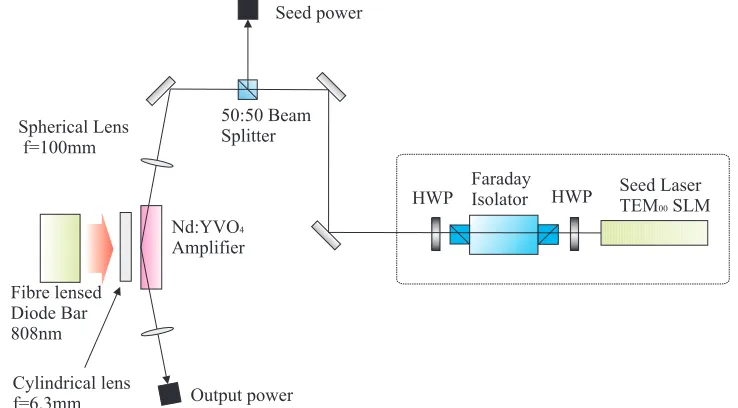
2.4.3 Single pass gain experimental . . . 51
2.4.3.1 Amplifier setup . . . 51
2.4.3.2 Lensed coupled pumping . . . 52
2.4.3.3 Proximity coupled pumping . . . 52
2.4.4 Single pass amplification results . . . 52
2.4.4.1 Lensed coupling results . . . 52
2.4.4.2 Proximity-coupling results . . . 53
2.4.5 Modelling the amplifier with multiple signal beams . 55 2.5 Four-wave mixing theory . . . 56
2.5.1 The holographic analogy . . . 56
2.5.1.1 Achieving phase conjugation through holog-raphy . . . 59
2.5.2 Writing a gain grating . . . 60
2.5.3 Diffraction from a gain grating . . . 64
2.5.3.1 The nonlinear polarisation due to a gain grat-ing . . . 65
2.5.3.2 The wave equations . . . 66
2.5.3.3 Numerical modelling . . . 68
2.5.4 Degenerate four-wave mixing . . . 69
2.5.5 Numerical modelling . . . 73
2.6 Degenerate four-wave mixing: experimental work . . . 75
2.6.1 Results . . . 76
2.6.1.1 Reflectivity as a function of signal beam power 76 2.6.1.2 Reflectivity as a function of relative pump beam intensities . . . 78
power . . . 81
2.7.1.2 Reflectivities as a function of total writing beam power . . . 81
2.7.2 Reflection gratings . . . 82
2.7.2.1 Reflectivities as a function of signal power . 82 2.7.2.2 Reflectivities as a function of total writing beam power . . . 83
2.7.2.3 Beam profile of the diffracted beam. . . 84
2.8 Cross polarisation experiments . . . 85
2.8.0.4 Alignment issues in a birefringent medium 85 2.8.1 Experimental . . . 89
2.8.1.1 Reflectivities as a function of probe beam power . . . 89
2.8.1.2 Reflectivities as a function of total writing beam power . . . 90
2.9 Discussion . . . 91
2.10 Conclusions . . . 92
2.11 References . . . 92
3 Towards a monolithic phase conjugator 95 3.1 Introduction . . . 95
3.2 Phase conjugate oscillator theory . . . 96
3.2.1 Fundamental operation . . . 96
3.2.2 Longitudinal modal structure . . . 98
3.2.2.1 Writing the grating . . . 98
3.2.2.2 Reading the gain grating . . . 99
3.3 Phase conjugate oscillator modelling . . . 101
3.4 Experimental . . . 105
3.5 Results . . . 106
3.5.3 Beam quality measurements . . . 109
3.5.3.1 Longitudinal modes . . . 109
3.5.3.2 Spatial beam quality . . . 110
3.6 Future work . . . 112
3.6.1 Methods of increasing the output power . . . 112
3.6.1.1 Controlling the transmission with an aper-ture . . . 112
3.6.2 A monolithic resonator . . . 114
3.7 Conclusions . . . 115
3.8 References . . . 116
4 The holographic resonator 117 4.1 Introduction . . . 117
4.2 Phase conjugate resonator theory . . . 117
4.2.1 Operation of the resonator . . . 118
4.2.2 The non-reciprocal transmission element . . . 118
4.2.2.1 A Jones matrix model of the NRTE . . . 120
4.2.3 Temporal properties . . . 122
4.3 Modelling the phase conjugate resonator . . . 123
4.3.1 Boundary conditions . . . 123
4.3.1.1 Side loop resonator . . . 123
4.3.1.2 Ring resonator . . . 124
4.3.1.3 Self-starting resonator . . . 125
4.3.2 Numerical modelling of output powers . . . 125
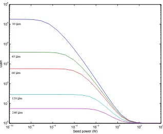
4.3.2.1 Modelled output powers as a function of seed power . . . 126
4.3.2.2 Modelled output powers as a function of loop transmission . . . 127
4.3.2.3 Intracavity flux modelling . . . 128
4.4.2 Ring resonator setup . . . 131
4.5 Results . . . 132
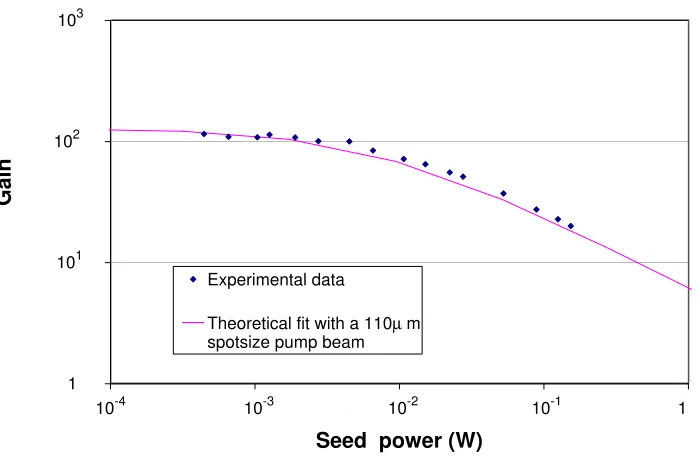
4.5.1 Output powers as a function of seed beam power . . 132
4.5.1.1 Ring resonator results . . . 132
4.5.1.2 Side loop resonator results . . . 133
4.5.2 Output powers as a function of loop transmission . . 133
4.5.2.1 Ring resonator results . . . 133
4.5.2.2 Side loop resonator results . . . 135
4.5.3 Ring resonator intracavity flux measurements . . . . 135
4.5.4 Frequency Spectrum . . . 137
4.5.5 Spatial beam quality . . . 137
4.5.6 Self-starting experiments results . . . 138
4.6 Discussion . . . 140
4.6.1 Operation of the resonator . . . 140
4.6.2 Comparing the geometries . . . 141
4.7 Conclusions . . . 142
4.8 References . . . 142
5 Power-scaling holographic resonators 144 5.1 Introduction . . . 144
5.2 Modelling the amplified resonator . . . 145
5.2.1 The positioning of a power amplifier . . . 145
5.2.1.1 The amplifier in position 1 . . . 145
5.2.1.2 The amplifier in position 2 . . . 147
5.2.1.3 The amplifier in position 3 . . . 148
5.2.2 Using the holographic resonator as a MOPA system . 148 5.2.3 The limitations of the phase conjugator . . . 151
5.2.3.1 Beam steering effects . . . 151
5.2.3.2 Thermally induced distortions . . . 155
5.4.1 Lasing results from the amplified holographic
res-onator . . . 158
5.4.2 Output as a function of NRTE HWP angle . . . 159
5.4.3 Intracavity flux . . . 161
5.4.4 Beam quality measurements for the MOPA system . 162 5.5 Discussion . . . 162
5.6 Conclusion . . . 165
5.7 References . . . 166
6 Four-wave mixing and holographic resonators in waveguides 167 6.1 Introduction . . . 167
6.2 Four-wave mixing in a fibre . . . 168
6.2.1 Two beam four-wave mixing . . . 168
6.2.2 Double-clad geometries . . . 170
6.2.3 Fibre based resonator . . . 170
6.3 Gain gratings in fibre amplifiers . . . 173
6.3.1 Gain saturation fibre amplifiers . . . 173
6.3.2 Gain available from a fibre amplifier . . . 174
6.3.3 Gain gratings in end-pumped fibres . . . 175
6.3.4 Diffraction efficiency of an end pumped gain grating 176 6.4 Experimental techniques . . . 177
6.4.1 Suppression of parasitic lasing . . . 177
6.4.1.1 Angling the fibre ends . . . 178
6.4.1.2 Fibre end caps . . . 178
6.4.2 Coupling light into multimode fibres . . . 179
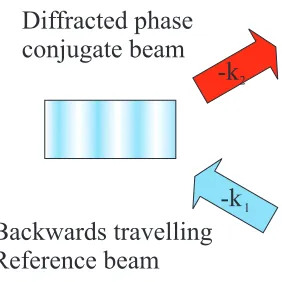
6.4.3 Identification of phase conjugate output . . . 180
6.5 Experimental . . . 181
6.5.1 Fibres used in these experiments . . . 182
6.5.2 Single clad fibre experiments . . . 182
6.5.4 Crystal fibre experiments . . . 185
6.5.4.1 Results . . . 186
6.6 Analysis . . . 187
6.6.1 Comparing the Parametric process with gain gratings 187 6.6.2 Scattering from other gratings and two-wave mixing 188 6.6.3 Overlap with the pump beams . . . 189
6.7 Conclusions . . . 189
6.8 References . . . 189
7 Conclusions 193 7.1 Summary . . . 193
7.1.1 Four-wave mixing via saturable gain gratings . . . . 193
7.1.2 Towards a monolithic phase conjugator . . . 194
7.1.3 The holographic resonator . . . 195
7.1.4 Power scaling the holographic resonator . . . 196
7.1.5 Four-wave mixing and holographic resonators in waveg-uides . . . 196
7.2 Further work . . . 197
7.2.1 A monolithic phase conjugator . . . 197
7.2.2 Hybrid systems . . . 197
7.3 References . . . 198
A Properties of the Nd:YVO4 crystal slab 199 A.1 Nd:YVO4properties . . . 199
A.2 Crystal coatings . . . 200
A.3 Crystal dimensions . . . 200
A.4 Crystal cooling and pumping . . . 200
A.5 References . . . 201
B.4 References . . . 206
C Degenerate four-wave mixing via gain saturation 209
C.1 Theory of gain grating formation and interactions . . . 209 C.2 References . . . 213
D Publications 214
A glossary of abbreviations and commonly used terms
AR Anti-reflection
ASE Amplified spontaneous emission
BP Backward pump
cc Complex conjugate
DFWM Degenerate four-wave mixing
FWM Four-wave mixing
FP Forward pump
HWP Half-wave plate
M2 A measurement of beam quality
MOPA Master oscillator power amplifier
NRTE Non-reciprocal transmission element
PC Phase conjugate
PCM Phase conjugate mirror
SBS Stimulated Brillouin scattering
SLM Single longitudinal mode
Introduction
1.1 Overview
In the first section of this chapter the concept of phase conjugation is intro-duced, and described both qualitatively and analytically. Its use in distor-tion correcdistor-tion is discussed and compared with the behaviour of a plane mirror. Various common methods of achieving phase conjugation are in-troduced and a comparison is made between them.
In the second section diode pumped solid state lasers will be discussed. The advantages of diode pumping will be described with respect to the high brightness and output powers in the CW regime. The neodymium (Nd3+) laser ion will be described for its use in a Nd:YVO
4 laser emitting
at 1.06µm . Heat deposition in solid state lasers due to the quantum defect and various up-conversions will be covered with respect to their effect on laser performance.
Existing methods of power scaling solid state lasers will then be described along with the use of phase conjugation to develop high power systems.
1.2 Phase conjugation
Phase conjugation was first observed by Zel’dovich [1] in 1972 but its roots can be traced back further to earlier work in static [2] and dynamic [3] holography. Zel’dovich passed a beam through an etched glass plate into a cell of compressed methane. He observed that the scattered beam exactly retraced the path of the incident beam through the glass plate cancelling out the phase distortions.
Two beams are considered to be phase conjugates of each other if they have the same wavefronts but the opposite propagation directions. This means that thek-vectors of the two beams have the opposite sign and that the amplitude functions of the beams are the complex conjugate of each other (which is where the name ’phase conjugate’ comes from).
When a beam is incident on a conventional mirror, only the component of thekvector that is perpendicular to the plane of the mirror is reversed. If a divergent beam is incident on a plane mirror its reflection will diverge in the same manner (Figure 1.1a). Hence for a beam reflecting from a flat mirror located in thex−yplane, reflection is given by
Aei((kx+ky+kz)·r−ωt) ⇒A0ei((kx+ky−kz)·r−ωt) (1.1)
If however the beam is incident on a phase conjugate mirror then all three components of the k vector of any incident beam will be reversed with a reflection given by
Aei((kx+ky+kz)·r−ωt) ⇒A0ei(−(kx+ky+kz)·r−ωt) (1.2)
inci-dent beam regardless of the initial spatial structure of the beam. Figure 1.1b shows the reflection of a divergent beam by a phase conjugate mirror.
a
b
Figure 1.1: a, Reflection from a plane mirror. b, Reflection from a phase conjugate mirror.
1.2.1 Distortion correction theory
One of the main uses of phase conjugation is for distortion correction. When a beam with a flat wavefront is passed through a phase aberrator (an etched glass plate for example) its transmitted wavefront will be dis-torted. If this distorted beam is then reflected by a conventional mirror it will pass back though the aberration again with the wavefront of the beam being further distorted (Figure 1.2).
This can be considered analytically by taking an ideal plane wave of the form
E(x, y, z, t) = A0(x, y, z)ei(kz−ωt) (1.3)
where E is the optical field andA0 its amplitude. The plane wave is then
Mirror
Phase distortion
Figure 1.2: Reflection from a conventional mirror causing cumulative aber-ration.
E0(x, y, z, t) = A0(x, y, z)ei(kz+φ(x,y,z)−ωt) (1.4)
where φ(x, y, z)describes the effect on the phase of the beam imposed by the phase aberration.
E0 is then reflected by a plane mirror with an amplitude reflectivity r to give
E00(x, y, z, t) =rA
0(x, y, z)ei(−kz+φ(x,y,z)−ωt) (1.5)
Which, on transmission back through the aberrator gives a final field of
E000(x, y, z, t) = rA0(x, y, z)ei(−kz+2φ(x,y,z)−ωt) (1.6)
The beam has now been passed through the distortion twice, each time distorting its wavefront further.
beam will have the same flat wavefront as the original beam (Figure 1.3).
Phase distortion
Phase conjugate
mirror
Figure 1.3: Reflection by a phase conjugate mirror cancels out any phase distortion.
This can be viewed analytically by taking the distorted beamE0(equation 1.4) with reflection via a phase conjugate mirror of reflectivityrpcto give
E00(x, y, z, t) =rpcA0(x, y, z)ei(−kz−φ(x,y,z)−ωt) (1.7)
Which when transmitted back through the phase aberrator results in a final beam of the form
E000(x, y, z, t) = r
pcA0(x, y, z)ei(−kz−φ(x,y,z)+φ(x,y,z)−ωt)
E000(x, y, z, t) = rpcA0(x, y, z)ei(−kz−ωt) (1.8)
The phase distortion that was imposed on the beam has been removed leaving an exact replica of the original beam travelling in the opposite di-rection.
It is also interesting to compare the expanded versions1of the initial and
phase conjugated beams.
1Up to now it has been assumed that cos(kz −ωt) = e−i(kz−ωt)rather than the full
E(x, y, z, t) = A0(x, y, z)(ei(kz−ωt)+e−i(kz−ωt))
= A0(x, y, z)(ei(kz−ωt)+ei(−kz+ωt))
E000(x, y, z, t) = r
pcA0(x, y, z)(ei(−kz−ωt)+e−i(−kz−ωt))
= rpcA0(x, y, z)(ei(kz+ωt)+ei(−kz−ωt)) (1.9)
It can be seen that when written in this form the only difference between
E000 and E is the sign of the time component (ωt) of the two beams and
rpc. This is why phase conjugate beams are sometimes referred to as being
”time reversed”. Obviously nothing is really travelling backwards in time but it helps to visualise how a phase conjugate exactly retraces the path of the original signal beam. This time reversal has been misunderstood in the past leading to pseudo scientific claims of ’magical’ properties [4].
1.2.2 Methods of achieving phase conjugation
Phase conjugation can be achieved via a range of nonlinear optical effects. The most commonly used methods of achieving phase conjugate are de-scribed here.
1.2.2.1 Stimulated Brillouin Scattering
Stimulated Brillouin Scattering (SBS) was the mechanism used in the first observation of phase conjugation by Zel’dovich [1] and has been used in the generation of phase conjugate waves ever since [5] [6] [7]. SBS is achieved by focusing a beam into some material where a counter-propagating beam is generated through stimulated scattering.
Initially a beam is launched into the SBS cell and spontaneously scatters off localised variations in the material2 (Figure 1.4a). The scattered beam
a. Spontaneous scatter from noise
b. Interference between incident and scattered light
c. Amplification of sound wave by electrostriction
d. Increased scattering from the intensified sound wave
I
inI
scI
inI
inI
inI
scI
scI
scwhich counter-propagates with respect to the initial beam overlaps with it forming an interference pattern (Figure 1.4b). This interference pat-tern then generates an acoustic wave via the electrostrictive effect 3
(Fig-ure 1.4c). The initial beam scatters off the acoustic wave reinforcing the back scattering (Figure 1.4d) and building up the signal. Any reflectiv-ity depends strongly on the length of the interference area causing the phase conjugated backscattered part to dominate. The acoustic compres-sion wave travels through the medium causing a Doppler shift in the phase conjugate beam.
The sound wave has an angular frequency (Ω)and travels in the same di-rection as thek-vector of the initial beam. The Doppler shift imposed on the reflected beam is given byωinc−ωref = Ω. This causes the interference
between the incident and reflected beams to beat at a frequency ofΩwhich will reinforce the acoustic wave.
The threshold at which SBS occurs can be estimated from
Pth ' 25Aef f
Lef fg
(1.10)
whereLef f is the effective interaction length (which depends on the
coher-ence length), andgis the Brillouin gain coefficient.
SBS has been observed in a wide range of substances (which tend to be highly toxic and/or require high pressures) but most of the recent work has been concentrated on solid state materials especially multimode silica fibres. Whilst these have lower SBS gains than the more traditional mate-rials (Brillouin gains of 130 cm/GW with a threshold of 18 kW have been achieved in CS2 [9] compared with 5.8 cm/GW with a 300 kW threshold
[10] in silica) this is compensated for by the ability to produce far longer
refractive index), defects in crystals, pressure variations in gases, or any form of impurity in the medium.
gain regions. SBS in multimode silica fibres has been used to achieve phase conjugate reflectivities of up to 90% [10]. Work is currently under way to try and bring SBS phase conjugation in fibres into the CW regime [11].
1.2.2.2 Four-wave mixing
Four-wave mixing is a form of dynamic holography where the hologram is simultaneously written and read by the same three beams [12]. Four-wave mixing has been achieved via a wide range of nonlinear effects; parametric amplification [13], photo-refractives [14], molecular reorientation effects in liquid crystals [15], saturable absorbers [16] and saturable gain [17]. In all of these cases the same fundamental mechanism applies.
FP
BP
Sig
PC
Nonlinear medium
a
b
c
Figure 1.5: Four-wave mixing. a, a schematic of the beams. b, a reflection grating formed between the backward pump(BP) and signal (Sig) beams. c, a transmission grating formed between the forward pump(FP) and sig-nal (Sig) beams.
In degenerate four-wave mixing three beams intersect in a nonlinear medium. Two of the beams (the backward and forward pump) are aligned such that they counter-propagate, while the third (the signal beam) intersects them at some angle (Figure 1.5a). Two interference patterns are formed4; one
tween the signal beam and the backward pump beam, the other between the signal and forward pump beam . These interference patterns write gratings in the medium by one of the nonlinear process previously men-tioned. The pump beam which was not involved in the writing of each grating then diffracts off it as a phase conjugate of the signal beam (Fig-ures 1.5b and c). In non-degenerate four-wave mixing the angles which the beams meet are chosen such that Bragg matching occurs between the incident beams and their corresponding gratings.
1.2.2.3 Self pumped photo-refractives
Self pumped phase conjugation via the photo-refractive effect [18] [19] is used for a wide range for optical techniques due to its ease of use and need of only low power beams (phase conjugation has even been observed with microwatt beams [20]).
Intensity
Interference
Pattern
Writing beams
+ +++ +++++ +++++++ + +++ +++++ +++++++ + +++ +++++ +++++++ --- -- --- - --- -- --- - --- -- --- ----Charge
+ +++ +++++ +++++++ + +++ +++++ +++++++ + +++ +++++ +++++++Electric
Field
- --- --- - --- --- - -- -------Refractive
index
change
Photo induced ionisation [image:27.595.122.476.177.643.2]Charges drift to a steady state distribution - -- ---
----p/2
a.
b.
c.
d.
e.
The change in refractive index due to the incident field is given by
4n=−1
2ref fEn
3
0 (1.11)
where ref f is some linear combination of components of the electrooptic
tensor element, E the electric field and n0 the unperturbed refractive
in-dex.
Self pumped photo-refractive phase conjugators operate via four-wave mixing but in a very interesting way. The device used by Feinberg [22] consists of a beam launched into a single crystal of BaTiO3. When the
beam is launched into the crystal (perpendicular to the crystal’s c-axis) it ‘fans out’ (due to the change in refractive index it induces via the photo-refractive effect) illuminating one of the edges of the crystal. This edge acts as a retro-reflector directing the light back towards the incident beam. Where two components of this beam counter-propagate (beams 2 and 2’ in figure 1.7) they form a two counter-propagating loop of light. At pointb
(and indeed pointa) beams 2 and 3 counter-propagate and intersect beam 1; this is a four-wave mixing geometry and as such generates a phase con-jugate of beam 1.
1
2’
2
3
3’
a
b
Figure 1.7: A self-pumped BaTiO3phase conjugator [22]
to some times many minutes. This build-up period is because the light induced refractive index change depends on the optical energy rather than the optical intensity of the incident beams [19].
1.2.2.4 Adaptive optics
Whilst the use of adaptive optics is not technically a form of phase con-jugation it is used for distortion correction and will be covered here for completeness. Increasingly nowadays adaptive control is used to define the spatial properties of laser cavities in a similar manner to our use of phase conjugation.
Adaptive optics involves the use of deformable mirrors to control the shape of a wavefront [23], and are used in a range of imaging regimes, for exam-ple in astronomy to reduce distortions caused by atmospheric fluctuations and in high power lasers for mode selection. Recently the highest intensity of laser light ever achieved (8.5×10²¹W/cm2 in a 1.2J, 27fs pulse) was
pro-duced using adaptive optics to focus the beam into a spot less than 1µm across [24].
Wave front monitor
Deformable mirror
Phase distortion
Feedback
system
Figure 1.8: An adaptive optics system
to a computer controlled feedback system as shown in figure 1.8. Here a beam is passed through a phase distortion (such as a pumped amplifier) then reflected by the deformable mirror back through the distortion. The reflected beam is sampled and the mirror dynamically molded to achieve correction for the distortion. The fidelity of wavefront replication is lim-ited by the density of actuators and maximum local radius of curvature of the mirror and accuracy of the feedback systems.
1.3 Diode pumped solid state lasers
The field of solid state lasers covers any laser whose host medium is a crystal, glass or ceramic. Solid state lasers have been the subject of a great deal of research since the creation of the first laser [25].
Early solid state lasers were mostly pumped with flashlamps which caused them to be bulky and inefficient. With the development of diode lasers came the first example of a diode pumped solid state laser [26] in 1964.
The development of high power diode lasers has revolutionised the field of solid state lasers. These devices produce high power, high brightness outputs yet are cheap and compact. Single emitter diodes have been built to achieve outputs of up to 10W [27] [28]. Many emitters can be combined into bars or stacks achieving outputs of, for diode bars 90W [29] and diode bar stacks of 1.3kW [30]. Diode lasers are ideally suited for pumping laser crystals due to their comparatively narrow bandwidth (compared with flashlamps), brightness and high power.
1.3.1 Neodymium as a laser ion
The neodymium ion (Nd3+) was the first trivalent rare earth ion to be used
in a laser. It is most commonly used in host materials such as YAG, YVO4,
YLF and glass, but stimulated emission has been achieved in over 100 dif-ferent host materials to date [31].
When pumped at 808nm the ion’s outer electron is excited to the 4F 5/2/ 2H
9/2 manifold, from where it rapidly de-excites down to the metastable 4F
3/2 level.
Lasing occurs predominantly on the 4F
3/2 →4 I11/2 transition at around
1.06µm (depending on the host medium). Lasing is also possible on the
4F
3/2 →4 I9/2and4F3/2 →4 I13/2transitions with emission at around 0.9µm
and 1.35µm respectively (again the exact emission wavelength is depen-dent upon the host medium).
[image:31.595.149.440.414.627.2]Pump Transition 808nm Lasing Transition 1064nm
F
I
non-Radiative decay non-Radiative decayI
F
H
4 5/2 2 9/2 4 3/2 4 11/2 4 9/2Figure 1.9: Nd3+ energy levels when pumped at 808nm emitting at
1.3.1.1 Nd:YVO4
Nd:YVO4 was first proposed for use as a laser material by O’Connor in
1966 [32] but it wasn’t until 1987 [33] that crystals of suitable optical qual-ity to build a viable system were available. Its high stimulated emission cross-section at the lasing wavelength (4.6 times greater than Nd:YAG [34]), short absorption length and wide absorption bandwidth (again com-pared with Nd:YAG) make it a very desirable laser crystal [35].
Nd:YVO4 is a naturally birefringent uniaxial crystal. Its stimulated
emis-sion cross-section is three times higher along the a-axis than that along thebandcaxes which leads to polarised laser output. This polarised out-put means that the thermally induced birefringence effects which Nd:YAG suffers from are avoided.
The material and lasing properties of 1.1%at doped Nd:YVO4are given in
table A.1.
1.4 Heat deposition in solid state lasers
Heat deposition in solid state lasers is a problem which severely limits possible output powers and beam qualities. The major causes of heating are the quantum defect and up-conversion. Problems with absorptions to non-radiative states have decreased since the replacement of flashlamp pumped systems with narrower bandwidth diode based pumping. How-ever, the high pump intensities achievable from diodes have themselves produced new problems.
1.4.1 The quantum defect
level and the lower laser level and ground state are allnon-radiative. The proportion of energy lost thermally can be calculated from
QD = Epump−Elasing
Epump
= 1− λlasing
λpump
(1.12)
When pumped at 808nm and lasing at 1064nm Nd:YVO4 loses 24% of the
pump power to heat through this process.
1.4.2 Up-conversion
When Nd3+lasers are pumped at 808nm several spectroscopic up-conversion
processes impede efficient laser action. These processes include energy transfer (or Auger) upconversion [36] [37] [38], excited state absorption [39] and cross relaxation [37].
1.4.2.1 Energy transfer upconversion
4
F
4
I
4
F
4
I
Ion 1
Ion 2
2
G
3/2
11/2
9/2
3/2 9/2
Energy transfer up-conversion occurs when two ions in the4F
3/2metastable
level are in close proximity. One of the ions relaxes down to the 4I 11/2
level [38] transferring its energy to the second ion which is in turn pro-moted to a higher state (2G
9/2). The excited ion relaxes down to the4F3/2
level non-radiatively (Figure 1.10).
1.4.2.2 Excited state absorption
A schematic of excited state absorption is shown in figure 1.11. A Nd3+ion
is excited by a pump photon to the4F
5/2 level, and it then rapidly relaxes
down to the metastable4F
3/2level. This is then followed by the absorption
of another pump photon which excites it up to the2D
5/2 level after which
it decays non-radiatively to the4G
7/2level.
4
F
4I
4F
2D
4G
5/2 7/2 5/2 3/2 9/2Figure 1.11: Excited state absorption.
1.4.2.3 Cross relaxation
Cross relaxation [37](also referred to as self quenching) occurs between an ion excited to the metastable4F
3/2level and an ion in its ground state. The
excited ion relaxes down to the 4I
15/2 level transferring its energy to the
other ion which is excited into the4I
15/2 level. Both ions then relax down
4
F
4
I
4
I
Ion 1
Ion 2
4
I
4
I
3/215/2 15/2
9/2 9/2
Figure 1.12: Cross relaxation.
1.5 Power scaling of lasers
One of the main uses of phase conjugation is in the power scaling of lasers. It is comparatively easy to build a low power laser which operates on a single spatial and longitudinal mode. Developing higher power systems is a much more complicated endeavour. Heating of the laser medium due to the quantum defect and parasitic spectroscopic processes cause changes in refractive index, thermal expansion and stress induced birefringence.
These effects are especially important now with the development of diode pumped solid state lasers. In the last 4 years diode power available from a single device has increased more than 10 fold from 40W diode bars up to the latest kilowatt stacks. With these powers comes the need to extract more heat than ever before.
1.5.1 Thermal lensing and distortions
distribution will be reached.
Heating of a laser medium causes the refractive index to change via two processes: Firstly, the linear thermally induced refractive index change and secondly through any stress induced refractive changes [40]. The com-bination of these effects and the ”bulging” or curvature of the mediums end faces form a lens. The strength of this lens depends on the thermal loading and material properties of the laser medium.
The focal length of a thermal lens is generally found to be inversely pro-portional to the power of the pump beam [42] [45]. The quality of the lens is dependent on the pump beam profile.
For a uniform or top hat pump distribution a parabolic variation in tem-perature and therefore refractive index profile is formed [43] (only within the pumped region in the case of the top hat distribution). This profile gives a lens with no higher order terms and as such shouldn’t aberrate any beam passing through it [46].
In a real laser system it is more common for the pump beam to have a Gaussian (or near Gaussian) profile. In this case a more complex refractive index profile is produced. The resultant lens will contain higher order phase terms which act to distort any beam that passes through it. In order to calculate the effect that these highly complex lenses have on the beam quality generally only the quartic phase aberrations are considered [42]. Seigman’s analysis [46] of the effect of quartic phase aberration due to a spherical lens gives the increase in the beam quality factor (M2) as
M2 = 8πC4w
4
λ√2 (1.13)
1.5.1.1 Methods of cooling
Solid state laser crystals are generally conduction cooled through their side faces. Conduction cooling is achieved by placing the laser crystal in good thermal contact with water cooled copper heatsinks. In order to achieve good thermal contact between crystal and heatsink heat paste, indium foil or wax are used. In low power lasers systems Peltier air cooling can re-place the water cooling.
In side pumped schemes this is through the top and bottom faces (Figure 1.13a). In end pumped schemes cooling is preformed through the edge faces of the rod (Figure 1.13b). Rods are generally used in end pumped systems in order to achieve symmetry in the heat distribution.
a
b
Figure 1.13: Cooling in, a, side pumped, and b, end pumped, laser crystals.
1.5.2 Existing power scaling solutions
1.5.2.1 MOPA systems
Master oscillator power amplifier (MOPA) systems (Figure 1.14) are cur-rently used to generate high power single (spatial and longitudinal) mode lasers. Generally a stable low power laser (the master oscillator) is built with a diffraction-limited, single frequency output. The beam generated by the master oscillator is passed through a Faraday isolator to prevent any feedback, then through the amplifier (or amplifier chain).
longitu-dinal) mode beam are de-coupled from the problems of power scaling the beam. This property allows high power lasers to be designed and built in such a way that their output power can be scaled by simply adding more amplifiers.
The powers available from MOPA systems under single mode operation are limited by the thermally induced distorting effects in the amplifiers. With out these effects you could theoretically just keep adding more and more amplifier modules to your laser and keep scaling in power indefi-nitely (as long as any parasitic lasing processes were being suppressed.). The presence of thermally induced distortions such as the quartic phase aberration means that even for the best amplifier designs beam quality will still suffer.
Master
oscillator Isolator
Amplifier
Amplifier
Figure 1.14: A MOPA system.
1.5.2.2 Double clad fibre amplifiers
Another method of avoiding thermal effects is the use of a waveguide ge-ometry, specifically double clad fibre amplifiers. In a double clad fibre amplifier (Figure 1.15) the signal beam is confined to a single mode core whilst the pump beam is transmitted through the (multi mode) cladding. This maintains the beam quality of the signal beam whilst allowing a mul-timode pump beam to be coupled to it. Fibre lasers of this sort pumped with beam shaped diode stacks have recently reached kilowatt power lev-els whilst maintaining single mode output.
Figure 1.15: Double clad fibre laser/amplifier.
by the ratio of the cladding area to the core area. The absorption length can be increased still further if required by using low dopant concentration fibres. The long absorption length reduces the thermal power deposited per meter to a level that can be easily dissipated.
High fibre lasers and amplifiers do however suffer from problems due to the vast intensities reached in their cores. These intensities can lead to problems with feedback due to nonlinear effects such as Brillouin and Raman scattering. Recent developments of large mode area fibres have helped to combat this [47]. Large mode area fibres have a very small dif-ference in refractive index between the core and cladding. This allows larger core area to be used (Thus increasing the power threshold of any in-tensity dependent non-linear processes) whilst maintaining confinement on one spatial mode.
1.5.3 Phase conjugate MOPA systems
The ability of phase conjugate systems to dynamically compensate for dis-tortions in beams makes them ideally suited for work in MOPA systems.
Master oscillator
Isolator
Amplifier
Amplifier Phase conjugate
mirror
Figure 1.16: Phase conjugate MOPA system.
average power withM2=1.2 [48]. The diffraction-limited signal beam was
generated by a low power master oscillator (approximately 1W) passed through an optical isolator then into the amplifier chain. On passing through the first amplifier the beam quality had deteriorated to M2' 5. The
dis-torted beam was reflected by the phase conjugate mirror (in this case a multimode silica fibre achieving phase conjugation via SBS) and passed back through the amplifiers. The final beam had a beam quality of M2=
1.9.
1.6 Thesis overview
The remainder of this thesis deals with the development of continuous wave phase conjugate systems operating via saturable gain gratings.
Chapter 2 covers the nonlinear process of gain saturation. Side pumped slab amplifiers in a grazing incidence (or bounce) geometry are described as a method of achieving high small signal gains. Four-wave mixing is introduced as a method of achieving phase conjugation in terms of a holo-graphic analogy. The process is then modelled using saturable gain grat-ings to achieve phase conjugation. Experimental data is then presented on the phase conjugate reflectivities. The contributions of the two gratings which aid phase conjugation are also covered.
Chapter 3 covers the development of a simple phase conjugate oscillator based on saturable gain four-wave mixing. The output powers and tem-poral properties are modelled and determined experimentally. The devel-opment of this into a monolithic system is also discussed.
Chapter 5 covers the development of the holographic resonator into a phase conjugate MOPA system. The system is modelled, then realised experimentally and its limiting factors discussed.
Chapter 6 describes the attempts made to achieve phase conjugation via saturable gain gratings in a multimode fibre. The concepts involved in four-wave mixing in fibres along with the various methods of achieving this are covered. Experimental attempts are made to try and observe phase conjugation, and the failure of these experiments is then explained.
1.7 References
[1] B. Ya. Zel’dovich, V.I. Popovichev, V.V. Ragul’skii, F.S. Faizullov, and P.N. Lebedev. Connection between the wave-fronts of the reflected and excited light in stimulated Mandel’shtam-Brillouin scattering.
Soviet Journal JEPT Letters, 15(3):160–164, 1972.
[2] H. Kogelnik. Holographic image projection through inhomogeneous media. The Bell System Technical Journal, 44:2451, 1965.
[3] W.P. Cathey. Holographic simulation of compensation for atmo-spheric wavefront distortions. Proceedings of the IEEE, 56:340, 1968.
[4] T Bearden. Aids:Biological warfare. Tesla Book Company, 1988.
[5] A. Yariv.Optical electronics, pages 670–684. Saunders College Publish-ing, fourth edition, 1991.
[6] B. Ya. Zel’dovich, N.F. Pilipetskii, and V.V. Shuknov.Principles of phase conjugation, pages 25–65. Springer Verlag, first edition, 1985.
[8] A. Heuer and R Menzel. Principles of phase conjugating Brillouin mirrors. In A. Brignon and J.P. Huignard, editors, Phase Conjugate Laser Optics, pages 19–62. John Wiley & Sons, Hoboken, 2004.
[9] G. J. Crofts, M. J. Damzen, and R.A. Lamb. Experimental and theo-retical investigation of 2-cell stimulated-Brillouin-scattering systems.
Journal of the Optical Society of America B-Optical Physics, 18(11):2282– 2288, 1991.
[10] H.J. Eichler, A. Mocofanescu, T. Riesbeck, and D. Risse, E. Bedau. Stimulated Brillouin scattering in multimode fibers for optical phase conjugation. Optics Communications, 15(4-6):427–431, 2002.
[11] M. Sj ¨oberg, M.L. Quiroga-Teixeiro, S. Galt, and S. H˚ard. Dependence of stimulated Brillouin scattering in multimode fibers on beam qual-ity, pulse duration, and coherence length. Journal of the Optical Society of America B-Optical Physics, 20(3):434–442, 2003.
[12] R.A. Fisher.Optical Phase Conjugation. Academic Press, London, 1983.
[13] A. Yariv and D. M. Pepper. Amplified reflection, phase conjuga-tion, and oscillation in degenerate four-wave mixing. Optics Letters, 1(1):16–18, 1977.
[14] J.P. Huignard, J.P. Herriau, P. Auborg, and E. Spitz. Phase-conjugate wavefront generation via real-time holography. Optics Letters, 4:21, 1979.
[15] D. Fekete, J. AuYeung, and A. Yariv. Phase-conjugate reflection by de-generate four-wave mixing in a nematic liquid crystal in the isotropic phase. Optics letters, 5(2):51–53, 1980.
[17] J. Reintjes and L. J. Palumbo. Phase conjugation in saturable ampli-fiers by degenerate frequency mixing. IEEE Journal of Quantum Elec-tronics, 18(11):1934–1940, 1982.
[18] A. Yariv.Optical electronics, pages 637–669. Saunders College Publish-ing, fourth edition, 1991.
[19] J Feinberg. Optical phase conjugation in photorefractive materials. In R.A. Fisher, editor, Optical Phase Conjugation, pages 417–443. Aca-demic Press, London, 1983.
[20] J.O. White, M. Cronin-Golumb, B. Fischer, and A. Yariv. Coherent os-cillation by self-induced gratings in photorefractive crystals. Applied Physics Letters, 40:450, 1982.
[21] A. Yariv. Optical electronics, page 642. Saunders College Publishing, fourth edition, 1991.
[22] J Feinberg. Self-pumped, continuous-wave phase conjugator using internal reflection. Optics Letters, 7(10):486–804, 1982.
[23] R. Tyson.Principles of adaptive optics. San Diego Academic Publishing, San Diego, 1991.
[24] O. Graydon. US team breaks power density record, 2004. IOP pub-lishing, http:\\www.Physicsweb.org.
[25] T. Maiman. Stimulated optical radiation in ruby.Nature, 187:493–494, 1960.
[26] R.J. Keyes and T.M. Quist. Injection luminescent pumping of CaF2:U3+ with GaAs diode lasers. Applied Physics Letters, 4(3):50–52,
1964.
diode lasers with narrow beam divergence. IEEE Journal on Selected Topics in Quantum Electronics, 7(2):334338, 2001.
[28] A. Al-Muhanna, L.J. Mawst, D. Botez, D.Z. Garbuzov, R.U. Martinelli, and J.C. Connolly. High-power (>10W) continuous-wave operation from 100-µm -aperture 0.97-µm -emitting Al-free diode lasers.Applied Physics Letters, 73(9):11821184, 1998.
[29] Thales. Laser diode bars, 2004. http:\\www.thales-laser-diodes.com. [30] Coherent. Diode lasers, 2004. http:\\www.coherentinc.com.
[31] W. Koechner. Solid-State Laser Engineering, page 37. Springer-Verlag, forth edition, 1996.
[32] J.R. O’Connor. Unusual crystal-field energy levels and efficient laser properties of YVO4:Nd. Applied Physics Letters, 9(11):407–409, 1966.
[33] R. A. Fields, M. Birnbaum, and C. C. Fincher. Highly efficient Nd:YVO4 diode-laser end-pumped laser. Applied Physics B-Lasers and
Optics, 51(23):1885–1886, 1987.
[34] A.W. Tucker, M. Birnbaum, C.L. Fincher, and J.W. Erler. Stimulated-emission cross section at 1064 and 1342nm in Nd:YVO4 . Journal of
Applied Physics, 48(12):4907–4911, 1977.
[35] W. Koechner. Solid-State Laser Engineering, pages 63–65. Springer-Verlag, forth edition, 1996.
[36] Y. Guyot, H. Manaa, J.Y. Rivoire, R. Moncorge, N. Garnier, E. De-scroix, M. Bon, and P. Laporte. Excited-state-absorption and upcon-version studies of Nd3+ -doped single crystals Y
3Al5O12, YLiF4 and
LaMgAl11O19. Physical Review B, 51:784–799, 1995.
[38] Y.F. Chen, C.C. Liao, Y.P. Lan, and S.C. Wang. Determination of the Auger upconversion rate in fiber-coupled diode end-pumped Nd:YAG and Nd:YVO4 crystals. Applied physics B-Lasers and Optics,
70(7):487490, 2000.
[39] L. Fornasiero, S. Kuck, T. Jensen, G. Huber, and B.H.T. Chai. Excited state absorption and stimulated emission of Nd3+ in crystals. part 2:
YVO4, GdVO4 and Sr5(PO4)3F. Applied Physics B-Lasers and Optics,
67:449–553, 1998.
[40] W. Koechner. Solid-State Laser Engineering, pages 406–468. Springer-Verlag, forth edition, 1996.
[41] J.K. Jabcy ´nski, K. Kopczy ´nski, and A. Szcze¸´sniak. Thermal lensing and thermal aberration investigations in diode-pumped lasers. Opti-cal Engineering, 35(12):3572–3578, 1996.
[42] W. A. Clarkson. Thermal effects and their mitigation in end-pumped solid-state lasers. Journal of Physics D-Applied Physics, 34(16):2381– 2395, 2001.
[43] T.J. Kane, J.M. Egglestone, and R.L. Byer. The slab geometry laser- : Part 2 thermal effects in a finite slab. IEEE Journal of Quantum Elec-tronics, 21(8):1195–1210, 1985.
[44] P. Hello, E. Durand, P. K. Fritschel, and C. N. Man. Thermal effects in Nd-YAG slabs 3d modeling and comparison with experiments. Jour-nal of Modern Optics, 41(7):1371–1390, 1994.
[45] J.C. Bermudez, V.J. Pinto-Robledo, A.V. Kir’yanov, and M.J. Damzen. The thermo-lensing effect in a grazing incidence diode-side-pumped Nd:YVO4 laser. Optics Communications, 210(1-2):75–82, 2002.
[47] N.G.R. Broderick, H.L. Offerhaus, D.J. Richardson, R.A. Sammut, J. Caplen, and L. Dong. Large mode area fibers for high power appli-cations. Optical Fiber Technology, 5(2):185–196, 1999.
Four-wave mixing in a saturable
gain medium
2.1 Introduction
In this chapter four-wave mixing via saturable gain gratings will be intro-duced as a method of achieving phase conjugation. Gain saturation will be described and the saturated form of the amplifier gain equations de-rived. Proximity and lensed coupling will be introduced as methods of side pumping Nd:YVO4 slabs with diode bars. The population inversion
and temperature distribution due to side pumping will be modelled for later use.
The side pumped slab will then be used as an amplifier by passing a sig-nal beam through the slab and reflecting it off the pumped face at a graz-ing incidence (A bounce geometry). This amplifier will be modelled for proximity and lensed coupled pumps and the gains achieved by the two methods will be compared.
field will be derived leading up to a model of the diffraction efficiency of the gratings, and the relative efficiency of transmission and reflection gain gratings will be compared experimentally.
Four-wave mixing will be introduced in terms of a holographic analogy and will subsequently be described analytically and modelled numeri-cally. Experimental data will be presented showing phase conjugate re-flectivities approaching 100 times.
2.2 Gain saturation
2.2.1 Gain saturation theory
The gain seen by a small signal (low power) probe beam passing through a four-level optical amplifier depends on the length of the amplifier, its population inversion and the stimulated emission cross section of the laser ion. The gain can be calculated from
dI(z)
dz =α0I(z) (2.1)
where I(z)is the probe beam intensity andα0 the small signal gain (ssg)
coefficient which is given by
α0 =N.σse (2.2)
where σse is the stimulated emission cross section and N the upper state
population density1.
Equation 2.1 can be solved for a probe beam of initial intensityI0to give
1In a four level system it can be assumed that the the population of the upper laser level (N2) is far greater than that of the lower level(N1). Hence we can approximate that
I(z) = I0eα0z (2.3)
In a real laser medium the gain that can be achieved also depends on the intensity of the probe beam.
When a probe beam is present in an optical amplifier it induces stimulated emission from the excited ions. This reduces the population inversion in the medium and causes the gain to decrease. In a homogeneous medium this effect can be quantified by modifying the gain coefficient to the form shown in equation 2.4 [1].
α= α0
1 + II(satz) (2.4)
where α is the gain coefficient and Isat the saturation intensity. The
sat-uration intensity is defined as the signal intensity needed to reduce the gain coefficient to half of its small signal value. The saturation intensity is calculated from
Isat =
hν σseτ
(2.5)
where his Planck’s constant, ν the frequency of the seed beam andτ the fluorescence lifetime.
The saturated gain coefficient (Equation 2.4) can now be used to modify the small signal gain equation (Equation 2.1) to give the saturable gain equation
dI(z)
dz =α0
I(z)
1 + IIsat(z) (2.6)
ln
µ
I(z)
I0
+ I(z)−I0
Isat
=α0z (2.7)
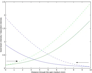
The effects of gain saturation on an amplifier can be seen in figure 2.1. Here a probe beam is passed through an amplifier with a small signal gain of 10. The green dotted line shows the gain seen without gain saturation taken into account, while the blue solid line shows the effect of gain saturation.
10−3 10−2 10−1 100
10−2 10−1 100 101
Seed intensity I/Isat
Output intensity I/Isat
Unsaturated gain
Saturated gain
Figure 2.1: A comparison of gains from saturated and unsaturated ampli-fiers.
2.2.2 Gain saturation in Nd:YVO
4Nd:YVO4 is a uniaxial crystal and as such has different stimulated
The stimulated emission cross sections along the a and b axis (see table A.1) are a factor of ∼3.5 less than that along the c-axis. The small signal gain coefficients (equation 2.2) and the saturation intensities (equation 2.5) differ by the same factor.
102 103 104 105 106 107 108 109
100 101 102 103 104
Gain
Input intensity (W/m2) Light parallel to the a−axis
Light parallel to the c−axis
Figure 2.2: The gain profile of beams polarised parallel to theaandc crys-tal axes.
2.3 Side pumping with laser diode bars
2.3.1 Methods of side pumping with diode bars
Laser diode bars are arrays of many closely packed single emitter laser diodes. The combined output of these emitters gives an elliptical beam ideal for side pumping slab amplifiers.
In the vertical direction (y) the bars aperture is roughly the same width as the wavelength of the light that it emits (The aperture is∼1µm compared with a emission wavelength of 0.8µm ). In this direction the beam is near diffraction limited with a large divergence angle (see figure 2.3b).
In the horizontal direction (z) the diode bar consists of many near diffrac-tion limited lasers placed next to each other. When these beams are com-bined the effect is roughly the same as a highly multimode beam (M2s of
thousands) being emitted from a 1cm aperture. This causes the beam to be emitted with a small diverge angle (see figure 2.3c).
y
z x
y
x
z
x
a, b, c,
Figure 2.3: a, A diode bar. b, Output diverges rapidly in the vertical (y) direction. c, Output diverges slowly in the horizontal (z) direction
2.3.1.1 Lensed coupling
Figure 2.4 shows the pump light from a diode bar being collimated by a fibre lens then focused onto the face of a laser crystal with a cylindrical lens. By adjusting the distance from the lens to the crystal the size of the pumped region can be controlled.
Fibre lens
Cylindrical lens
Laser
diode bar
Crystal
Water cooled
heat sink
Figure 2.4: Side pumping with a lens-coupled diode-bar pump system.
2.3.1.2 Proximity coupling
Proximity coupling a diode bar to a crystal involves placing the diode bar next to the crystal and directly coupling in the light, as shown in figure 2.5.
Laser diode bar
Crystal
Water cooled heat sink
f
d r
Figure 2.5: Side pumping with a proximity coupled diode bar system.
the facet height has little effect, the recess of the emitters into the bar can be up to 200µm , severely limiting the potential spot size.
The vertical pump spot size (wpy)at the crystal face can be calculated from
the(FWHM)divergence angle of the diode (θdiv) which is typically around
35◦ , the facet height (f), recess (r) and distance from the diode bar to crystal face (d).
wpy =
f+ 2(d+r) tan(θdiv)
2 (2.8)
2.3.2 Side pumping Nd:YVO
4crystal slabs
The amplifiers used in the majority of the bulk work found in this thesis are 1.1%at dopedacut Nd:YVO4 slabs. These slabs are described in detail
in appendix A. They are (unless otherwise stated) all 1mm by 5mm by 20mm with a 3 degree wedge to prevent parasitic lasing. The frontb-face (1mm by 20mm) is AR (anti reflection) coated for 808nm and the two side
a-faces are AR coated for 1064nm. The crystals are water cooled through copper heat sinks on the top and bottomc-faces (5mm by 20mm).
2.3.2.1 Modelling the pump distribution
The pump distribution through the amplifier is dependent on the pump absorption length, spot size at the crystal face and beam divergence. The absorption coefficient (αp) at 808nm for pump light polarised parallel to
the crystalc-axis in 1.1%at doped Nd:YVO4is 31.2 cm−1(9.2 cm−1for light
polarised parallel to the a-axis). The short absorption length means that 99% of the pump light is absorbed in the first 1.5mm of the crystal.
The vertical beam quality of the pump beam from the diode bars used in these experiments was M2
and M2
y = 5 for the 40W IMC bars. When these are focused with a 6.3mm
focal length lens a∼30µm spot size is achieved.
Zr =
πw2 0n
M2λ (2.9)
The Rayleigh range (Zr) of the pump beam is ∼900 µm (calculated from
equation 2.9)which is significantly less than the absorption length (1/e2∼300µm
). This means that it is justified to assume that the radius of the pump beam does not change across the pumped region, and as such any divergence of the pump beam can be ignored.
z
x y
Figure 2.6: The pump distribution in a side-pumped crystal.
Figure 2.6 shows a schematic of the pump distribution in a side-pumped Nd:YVO4 crystal. The intensity of the pump beam through the crystal is
given by (using the coordinate set defined in figure A.2)
I(x, y, z) =
I¡−x0 2 ,0,0
¢
e
−2y2
w2py e−αp(x−−x20) if|z|< w
pz
0 if|z|> wpz
(2.10)
assuming a Gaussian distribution of power inyand a top hat distribution inz. wpy is the pump beam vertical spot size (∼30µm ) andwpz the pump beam width (remaining approximately constant at 1cm).
Pincident =
Z
area Ip
µ −x0
2 , y, z
dA
=
Z y=∞
y=−∞
Z z=−z0
2
z=−z0 2
Ip
µ −x0
2 , y, z
dy.dz
= Ip(
−x0
2 ,0,0)wpz
Z y=∞
y=−∞
e
−2y2 w2py dy
= Ip
µ −x0
2 ,0,0
wpywpz
r
π
2 (2.11)
Rearranging equation 2.11 for Ip
¡−x0
2 ,0,0
¢
and substituting it into equa-tion 2.10 gives
Ip(x, y, z) =
Pincident
wpywpz
√
π/2e −2y2
w2py e−αp(x−−2x0) if|z|< w
pz
0 if|z|> wpz
(2.12)
2.3.2.2 Population inversion
The steady state population inversion of a laser medium can be calculated from the pump rate and fluorescence lifetime.
The pump rate (R) is given as the number of excited ions created per sec-ond per unit volume (assuming no ground state depletion or competing spectroscopic processes). The pump beam is travelling in the x-direction so the depletion along this axis is used to find the number of ions created.
R(x, y, z) = − d
dxIp(x, y, z)
1
hν (2.13)
R(x, y, z) = αpIp(x, y, z)
which gives the population inversion at all points in the crystal of
N(x, y, z) = αpIp(x, y, z)τf
hν (2.15)
2.3.3 Thermal effects in side-pumped amplifiers
When any laser medium is pumped, heat is deposited. In Nd:YVO4this is
via the quantum defect [2] and spectroscopic effects such as energy trans-fer upconversion [3], which are discussed in detail in Koechner [4].
2.3.3.1 Temperature distribution
The temperature distributions for side-pumped slabs in single bounce and zigzag geometries have been studied for a range of materials (see refer-ences [5] , [6] and [7] for examples). More recently the steady state thermal load on a side-pumped Nd:YVO4 crystal slab with cooling from the top
and bottom (the c-faces) has been calculated by Bermudez et al [8]. His so-lution is derived from a superposition of the soso-lution to the homogeneous heat equation and the particular solution for the boundary conditions [7] and can be found in appendix B. The boundary conditions and materials used in Bermudez’s solution to the heat equation are exactly the same as those used in the experiments in Nd:YVO4 in this thesis and his model for
the temperature distribution will therefore be used.
−2.50 −2 −1.5 −1 −0.5 0 0.5 1 1.5 2 2.5 20
40 60 80 100 120 140
Distance through the crystal along the x−axis at y=0, z=0 (mm)
Temperature increase (degrees C)
Pump = 1W Pump = 2W Pump = 4W Pump = 8W Pump = 16W Pump = 32W Pump = 64W
Figure 2.7: The temperature distribution through a side-pumped Nd:YVO4 slab as a function of distance through the crystal along the
x-axis at y=0, z=0 (mm).
−0.50 −0.4 −0.3 −0.2 −0.1 0 0.1 0.2 0.3 0.4 0.5 20
40 60 80 100 120 140
Distance through the crystal along the y−axis at x=x
0/2, z=0 (mm)
Temperature increase (degrees C)
Pump = 1W Pump = 2W Pump = 4W Pump = 8W Pump = 16W Pump = 32W Pump = 64W
Figure 2.8: The temperature distribution through a side-pumped Nd:YVO4 slab as a function of distance through the crystal along the
−100 −8 −6 −4 −2 0 2 4 6 8 10 20
40 60 80 100 120 140
Distance through the crystal along the x−axis at x=x
0/2, y=0 (mm)
Temperature increase (degrees C)
Pump = 1W Pump = 2W Pump = 4W Pump = 8W Pump = 16W Pump = 32W Pump = 64W
Figure 2.9: The temperature distribution through a side-pumped Nd:YVO4 slab as a function of distance through the crystal along the
z-axis at x=x0/2, y=0 (mm).
2.3.3.2 Refractive index distribution
The refractive index change due to the thermal load in a pumped crys-tal can be calculated from the sum of the effective temperature-induced refractive index changes and the thermally induced stress.
∆ni(x, y, z) =
µ
dn dT
ef f
T(x, y, z)−Bef fσii (2.16)
Where T is the temperature increase, (dn/dT)ef f is the effective temper-ature dependent refractive index coefficient and Bef f is the stress optical
coefficient (both of these terms are dependent on the polarisation of the light passing through the crystal). σii is the stress in direction i where
i=x, y, z[5]
Bermudez [8] shows that in side-pumped slabs of Nd:YVO4with a bounce
![Figure 1.6: The photo-refractive mechanism (after [21])](https://thumb-us.123doks.com/thumbv2/123dok_us/8518266.352254/27.595.122.476.177.643/figure-the-photo-refractive-mechanism-after.webp)