Rochester Institute of Technology
RIT Scholar Works
Theses Thesis/Dissertation Collections
1-2014
Design Trade-offs for reliable On-Chip Wireless
Interconnects in NoC Platforms
Manoj Prashanth Yuvaraj
Follow this and additional works at:http://scholarworks.rit.edu/theses
This Thesis is brought to you for free and open access by the Thesis/Dissertation Collections at RIT Scholar Works. It has been accepted for inclusion in Theses by an authorized administrator of RIT Scholar Works. For more information, please [email protected].
Recommended Citation
1
Design Trade-offs for reliable On-Chip Wireless
Interconnects in NoC Platforms
by
Manoj Prashanth Yuvaraj
A Thesis Submitted in Partial Fulfillment of the Requirements for the Degree of Master of Science in Computer Engineering
Supervised by Dr. Amlan Ganguly
Department of Computer Engineering Kate Gleason College of Engineering
Rochester Institute of Technology Rochester, NY
January, 2014
Approved By:
_____________________________________________________________________________________________________
Dr. Amlan Ganguly
Primary Advisor – R.I.T. Dept. of Computer Engineering
_____________________________________________________________________________________________________
Dr. Andres Kwasinski
Secondary Advisor – R.I.T. Dept. of Computer Engineering
_____________________________________________________________________________________________________
Dr. Muhammad Shaaban
2
Dedication
I would like to dedicate this thesis to my parents Mr. A.R. Yuvaraj and Mrs. Sathya
Praba Yuvaraj and my brother Madan Kumar Yuvaraj who have supported me from
the beginning of this journey. I would also like to dedicate this to my mentor and all
3
Acknowledgements
I take this opportunity to express my profound gratitude and deep
regards to my primary advisor Dr. Amlan Ganguly for his exemplary
guidance, monitoring and constant encouragement throughout this thesis.
Dr. Ganguly dedicated his valuable time to review my work constantly and
provide valuable suggestions which helped in overcoming many obstacles
and keeping the work on the right track. I would like to express my deepest
gratitude to Dr. Andres Kwasinski and Dr. Muhammad Shaaban for sharing
their thoughts and suggesting valuable ideas which have had significant
impact on this thesis. I am grateful for their valuable time and cooperation
during the course of this thesis. I also take this opportunity to thank my
research group members for all the constant support and help provided by
them.
Lastly, I would like to thank my family and friends for their constant
motivation, encouragement and heartfelt support during the course of this
4
Abstract
The massive levels of integration following Moore’s Law making modern
multi-core chips prevail in various domains ranging from scientific applications to
bioinformatics applications for consumer electronics. With higher and higher
number of cores on the same die traditional bus based interconnections are no
longer a scalable communication infrastructure. On-chip networks were proposed
enabled a scalable plug-and-play mechanism for interconnecting hundreds of cores
on the same chip. Wired interconnects between the cores in a traditional
Network-on-Chip (NoC) system, becomes a bottleneck with increase in the number of cores
thereby increasing the latency and energy to transmit signals over them. Hence,
there has been many alternative emerging interconnect technologies proposed,
namely, 3D, photonic and multi-band RF interconnects. Although they provide
better connectivity, higher speed and higher bandwidth compared to wired
interconnects; they also face challenges with heat dissipation and manufacturing
difficulties. On-chip wireless interconnects is one other alternative proposed which
doesn’t need physical interconnection layout as data travels over the wireless
medium. They are integrated into a hybrid NOC architecture consisting of both
wired and wireless links, which provides higher bandwidth, lower latency, lesser
area overhead and reduced energy dissipation in communication. An efficient media
access control (MAC) scheme is required to enhance the utilization of the available
bandwidth. A token-passing protocol proposed to grant access of the wireless
5
the communication channel to one although multiple wireless hubs are deployed
over the chip. In principle, a Frequency Division Multiple Access (FDMA) based
medium access scheme would improve the utilization of the wireless resources.
However, this requires design of multiple very precise, high frequency transceivers
in non-overlapping frequency channels. Therefore, the scalability of this approach is
limited by the state-of-the-art in transceiver design. The Code Division Multiple
Access (CDMA) enables multiple transmitter–receiver pairs to send data over the
wireless channel simultaneously. The CDMA protocol can significantly increase the
performance of the system while lowering the energy dissipation in data transfer.
The CDMA based MAC protocol outperforms the wired counterparts and several
other wireless architectures proposed in literature in terms of bandwidth and
packet energy dissipation.
However, the reliability of CDMA based wireless NoC’s is limited, as the
probability of error is eminent due to synchronization delays at the receiver. The
thesis proposes the use of an advanced filter which improves the performance and
also reduces the error due to synchronization delays. This thesis also proposes
investigation of various channel modulation schemes on token passing wireless
NoC’s to examine the performance and reliability of the system. The trade-off
between performance and energy are established for the various conditions. The
6
Contents
Dedication………. ... 2
Acknowledgements ... 3
Abstract………. ... 4
Chapter 1. Introduction ... 11
1.1. End of Uniprocessor systems ... 11
1.2. Early multi-core interconnections ... 12
1.3. Network-on-Chip Paradigm (NoC) ... 13
1.4. Switching techniques... 14
1.5. Emerging interconnects ... 16
1.6. Thesis Contributions ... 19
Chapter 2. Related Work ... 22
Chapter 3. Network Architecture ... 24
3.1. Small World topology ... 25
3.2. On-chip Antennas ... 27
3.3. CDMA Based Wireless Interconnects... 29
3.4. CDMA MAC protocol ... 31
3.5. Adaptive CDMA protocol ... 33
3.6. Data Routing ... 34
3.7. Performance Metrics ... 35
3.8. Achievable Bandwidth of the CDMA-WiNoC ... 38
3.9. Packet Energy Dissipation ... 39
3.10. Performance Evaluation with varying Packet Size ... 43
7
3.12. Area Overheads ... 47
Chapter 4. Reliability analysis of the CDMA WiNoC... 50
4.1. Interference of a Matched Filter ... 50
4.2. Interference Suppression using Advanced Decoder... 56
4.3. Advance Modulation Schemes ... 63
Chapter 5. Conclusion and future work ... 66
5.1. Summary ... 66
5.2. Future Work ... 67
8
List of Figures
Figure 1-1: Transistor count & Moore’s law (reproduced from [1]) ... 12
Figure 1-2: Network-on-Chip architecture ... 15
Figure 1-3: Network Switch with virtual channels ... 16
Figure 3-1:CDMA-WiNoC Architecture ... 27
Figure 3-2: (a) On-chip metal zig-zag antenna(reproduced from [3]) (b) On-chip antenna placement on the die(reproduced from [23]) ... 29
Figure 3-3: The adopted CDMA (a) encoder and (b) decoder ... 32
Figure 3-4: Peak achievable bandwidth of mesh, SWNoC and CDMA-WiNoCs for 64,128 and 256 core systems ... 39
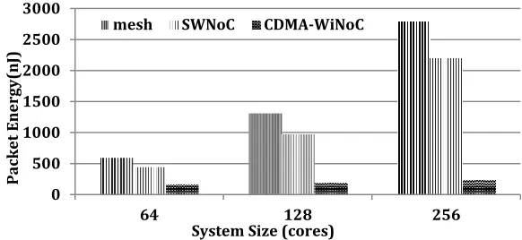
Figure 3-5: Packet energy dissipation of mesh, SWNoC and CDMA-WiNoCs for 64,128 and 256 core systems ... 40
Figure 3-6: Energy breakup comparison for (a) Mesh (b) SWNoC and (c) CDMA-WiNoC ... 41
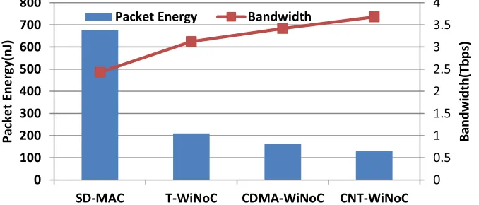
Figure 3-7 : Peak Bandwidth and Packet Energy dissipation comparison of various WiNoCs with 64 cores. ... 41
Figure 3-8 : Packet Energy dissipation and Throughput comparison of various packet sizes with 64 cores ... 43
Figure 3-9 : Bandwidth comparison of various non-uniform traffic in CDMA-WiNoC with 64 cores ... 45
Figure 3-10: Area overheads of various WiNoCs with 64 cores. ... 48
9
Figure 4-2: The effects of delay between two CDMA signals in misaligning the
spreading code sequences ... 52
Figure 4-3: SIR (dB) vs ... 54
Figure 4-4 : Flow diagram of CDMA decoder with MVDR filter. ... 60
Figure 4-5: (a) SIR(dB) vs Chip Shifts (b)SINR(dB) vs Chip Shifts ... 61
Figure 4-6: Energy Comparison between matched filter and MVDR filter. ... 62
10
List of Tables
Table 1: Characteristics of the Transceiver Modules ... 38
Table 2: Percentage of busy and idle cycles in a 64-core system given default
problem sizes ... 46
11
Chapter 1.
Introduction
The integration of transistors on a single chip is increasing at a massive scale
following Moore’s law. While moving into the billion-transistor era, chip designers
are encouraged to come up with computationally powerful processors pervasive in
several domains ranging from astrophysics, weather forecasting, and bioinformatics
to consumer electronics.
1.1.
End of Uniprocessor systems
In, figure 1-1, a plot of the transistor count versus their introduction timeline
is shown, where it can be observed that from the past few years, there is a shift to
incorporate multiple core systems on a chip instead of the traditional single
processor systems. [1]
The traditional method of increasing the operating frequency in a
uni-processor system in order to achieve better performance has reached its limit due to
the soaring power dissipation. The increase in power density and switching activity
due to increase in frequency results in higher power dissipation. Hence designers
have shifted to designing multiple cores on a single chip. This surely avoided the
limiting frequency problem and increased the computational power of the system
by introducing core-level parallelism. However it also posed a new challenge of
interconnecting these multiple cores. As the number of cores increases, the
12
Figure 1-1: Transistor count & Moore’s law (reproduced from [1])
1.2.
Early multi-core interconnections
Initial dual-core systems like IBM Power4/5, Intel Pentium Core Duo systems
had their cores communicating with each other by sharing memory. However if the
number of cores are increased, there is a need for more sophisticated interconnects
to deliver better performance in terms of throughput and latency.
Current multi-core systems predominantly use shared-bus based or a peer to
peer based architecture for interconnecting different cores on a chip. These
13
in shared bus architecture, the bandwidth available to each core reduces resulting in
lower throughput and increased contention delays. Hence the system becomes non
scalable beyond a certain limit. In case of a peer to peer network, though it provides
good connectivity among cores, it would be impractical to scale the system beyond a
certain limit due to the huge amount of wiring needed to connect all the cores
together. Hence there is a need for a scalable interconnect system which addresses
these issues. Also, the delay exceeding a single clock cycle due to increasing wire
delay with increase in wire length makes it hard to maintain a globally synchronized
system.
1.3.
Network-on-Chip Paradigm (NoC)
To overcome the above mentioned problems, research has been going on to
develop a communication centric approach to integrate cores on a single chip. This
new approach of designing scalable communication fabrics between the cores is
called the Network-on-Chip (NoC) paradigm. [2] This approach separates the
processing elements (i.e. cores) from the communication network as shown in
figure 1-2. It is a scalable plug-and-play system where the communication
infrastructure is isolated from the functionality of the cores. The data, usually in a
packetized form routes between cores over a dedicated interconnection network
consisting of network switches and inter-switch links. Such an approach facilitates
14
1.4.
Switching techniques
For a conventional NOC system, there can be basically three types of
switching that can be considered for data routing. Namely, Circuit Switching, Packet
Switching and Wormhole Switching.
In case of circuit switched networks, a dedicated path is reserved for the
complete duration of the transmission. Even though the network bandwidth is
reserved during the transmission it is highly inefficient when there are many nodes
waiting for transmission along the same path which eventually degrades the system
performance.
In case of packet switching, data is divided into packets and sent over the
network to the destination. Even though there is no reservation of path for
transmission, the packets needs to be buffered in the switches along the path to the
destination. In an SOC, this means more area overhead for the switches which are
not acceptable as on-chip silicon real estate is limited.
In this research work, wormhole switching is adopted wherein packets are
divided into small units called flow control units or flits. The size of flit is chosen
such that a single flit can traverse a single hop in a single clock cycle. These flits are
transmitted along the network across switches .Hence the large buffer requirement
for the switches are avoided. The first flit or the header flit of a packet contains the
routing information .This information enables the switches to setup the path and the
rest of the flits follow this path in a pipelined fashion [2]. But a problem associated
with such a switching technique is that distinct messages cannot be sent over a
15
is completely transmitted. Hence to solve this problem a concept called virtual
[image:16.612.80.488.158.549.2]channels was introduced.
Figure 1-2: Network-on-Chip architecture
Basically a virtual path is reserved for each distinct message. This is
accomplished by reserving separate buffers for each message in all the switches
along the path, forming a distinct virtual path for each message. Figure 1-3 shows a
16
separate buffers along the path which enables the switch to receive and send
[image:17.612.78.502.162.300.2]messages from both the nodes, simultaneously using a multiplexer.
Figure 1-3: Network Switch with virtual channels
1.5.
Emerging interconnects
In the future as the technology shrinks, longer wired interconnects would
result in higher power dissipation and delay. According to the International
Technology Roadmap for Semiconductors (ITRS) interconnects are the major
bottlenecks to overcome the power-performance barrier in the future generations.
This clearly indicates the challenges facing future chip designers associated with
traditional scaling of conventional on-chip, metal/dielectric based interconnects. To
enhance the performance of such conventional interconnect-based multi-core chips
a few radically different interconnect technologies are being currently explored;
such as 3D integration, Photonic interconnects and multi-band RF or wireless
interconnects [3, 4]. All these new technologies along with appropriate signaling
techniques have been predicted to be capable of enabling multi-core NoC designs,
17
However, these alternative interconnect paradigms are in their formative stage and
need to overcome significant challenges pertaining to integration and reliability.,
The following paragraphs explain each of these emerging interconnects briefly.
Three-dimensional integration consists of integrating multiple active layers
onto a single chip. Some of the advantages are that it results in lesser hop counts due
to the reduction in the number of interconnections and their average lengths. But as
claimed in [2], it has its disadvantages as well. Due to smaller foot print, the power
density on a 3-D structure would be high which causes high heat dissipation. Also
there are technological challenges in actually fabricating such structures such as
thinning of wafers, inter-device layer alignment, bonding, and interlayer contact
patterning [5]. Moreover, this also increases the risk of manufacturing defects and
also demands new CAD tool which support 3D integration.
In photonic interconnects, wired interconnects are replaced with optical
interconnects. It is stated in [6] that such interconnects would considerably enhance
the bandwidth and decrease latency as the data would be transmitted at the speed
of light. In [7] it is mentioned that due to the low loss in optical waveguides, data
could be transmitted from one end to the other without the need for regeneration
and buffering. However, some of the challenges in this field are the technology
needed to manufacture these photonic devices which is still in preliminary stages.
Also integrating these devices with silicon-compatible circuits under the constraints
of area, delay and other performance metrics remains a challenge.
Normally in a wired interconnect; data is transmitted by charging and
multi-18
band RF interconnects, data is transmitted by sending electromagnetic (EM) waves
along the wires that act as transmission lines. The data is modulated onto a carrier
using amplitude or phase shift keying [8]. Data bandwidth over the wire can be
increased by combining multiple non-overlapping carriers onto a single
transmission line. Also, EM waves travel at the speed of light. Hence, low latency and
high bandwidth communication can be achieved. However, designing high
frequency oscillators and filters on the chip for the transceivers is a non-trivial
challenge.
On-chip wireless interconnects is an alternative to wired links wherein long
wired paths are replaced with wireless interconnects. In addition to better
bandwidth utilization, lower delays and avoiding cross-talk interference in wired
interconnects, it also stands out from the rest of the emerging interconnects in the
sense that, they don’t need physical interconnection layouts as data travels in free
space.
Long range wireless shortcuts were introduced between distant cores on the
chip in [3]. However, the limited bandwidth of the wireless channels at such high
frequencies limits the achievable performance benefits. In this work Code Division
Multiple Access (CDMA) based long-range wireless links are used to enable multiple
transmitters sharing the wireless channel simultaneously. It is already shown in [4]
increasing the number of parallel communications over the wireless channel can
improve the performance as the network is better connected even though the total
wireless bandwidth is shared between the links. However, the reliability of CDMA
19
synchronization delays at the receiver. Hence there is a need for different
modulation schemes and advanced transceiver design, which are more efficient.
1.6.
Thesis Contributions
In this thesis work it will be demonstrated that by using various modulation
schemes, the wireless NoCs can be designed to achieve higher throughput and
dissipate lower energy compared to the conventional wired/wireless counterparts
without significant area overheads. The MVDR filter will be implemented and will
prove to be more effective than the previous CDMA decoder. Furthermore, the
numbers of wireless users in the CDMA network will be varied to obtain
performance and packet energy dissipation. The trade-off between performance and
energy will be established for the various conditions. The following point
summarizes the contributions made during this work.
Proposed Development of Network
Development and design of an advanced transceiver for improved
efficiency.
Design of efficient wireless NoC architecture with CDMA based
interconnects using advanced modulation schemes.
Reliability analysis
Reliability analysis of the CDMA based MAC protocol over the wireless
medium.
Evaluating effect of loss of synchronization on the reliability of the
20
Development of an advanced decoder to improve the reliability of the
wireless interconnects.
RTL Design
Develop the RTL level design of the CDMA encoder and decoder and
synthesize using 65nm standard cell libraries.
Develop the RTL level design for the model of the advanced decoder
used to improve the reliability of the wireless interconnects.
Development of simulations framework
Develop a cycle accurate simulator to implement the wireless NoC
architectures with 3-stage switches namely, input, output arbitrations
and routing to determine the following parameters
Obtain experimental results of the various MAC protocol wireless
NoC architecture with other wired and wireless architectures with
respect to the following parameters using the cycle accurate simulator
Peak achievable bandwidth
Packet energy dissipation
Non-uniform traffic patterns
Scalability - Increasing packet sizes
Area overheads
Publications
21
of the ACM Journal on Emerging Technologies in Computing Systems (JETC), October 9 2013. b. Naseef Mansoor, Manoj Prashanth Yuvaraj,
Amlan Ganguly “A Robust Medium Access Mechanism for Millimeter-Wave Wireless Network-on-Chip Architectures” Proceedings of the IEEE International System-on-Chip Conference (SOCC), Erlangen, Germany, September 04-06, 2013.
c. Naseef Mansoor, Manoj Prashanth Yuvaraj, Amlan Ganguly “An Energy-Efficient and Robust Millimeter-Wave Wireless Network-on-Chip Architecture” Proceedings of the IEEE International Symposium on Defect and Fault Tolerance in VLSI and Nanotechnology Systems (DFT), New York, United States of America, October 02-04 2013.
The following thesis is broken down into many sections as follows
Chapter 2: Related Work – This chapter talk about the previous technologies and
developments similar to this field of work.
Chapter 3: Network Architecture – This chapter explains in detail the required
elements for the network on chip used for this work.
Chapter 4: Reliability – This chapter derives the reliability of the previous work
and introduces an advance decoder design.
Chapter 5: Conclusion and Future Work – This chapter concludes all the results
22
Chapter 2.
Related Work
There have been many NOC architectures proposed. In [2], the authors lists
the most prominent interconnect architectures suggested so far which includes
SPIN (Scalable, Programmable and Integrated Network), CLICHE (Chip-Level
Integration of Communicating Heterogeneous Elements), torus, folded torus,
octagon and Butterfly Fat-Tree (BFT). However if all of these topologies are
implemented as completely wired interconnects, none of them would be scalable
beyond a certain point. This is because as the technology shrinks, delay and power
dissipations on traditional metal wires become the limiting factor in performance
compared to gate delays. Also as the wires become thinner, they become more
susceptible to noise and thus become less reliable.
Recently, the design of a wireless NoC based on CMOS Ultra Wideband
(UWB) technology was proposed [9]. In [10] a wireless Media Access Control (MAC)
protocol based on time-multiplexing of ultra-short pulses from the UWB
transceivers was proposed to enable concurrent use of the wireless channels. A
wireless NoC with unequal RF transceivers is proposed in [11] to improve the
performance in a conventional mesh topology overlaid with wireless interconnects.
In [12] the design of on-chip wireless communication network with miniature
antennas and simple transceivers that operate at the sub-THz range of 100-500 GHz
has been proposed.
Design of a wireless NoC using the small-world topology using carbon
nanotube (CNT) antennas operating in the THz frequency range is elaborated in [3].
23
to communicate using Frequency Division Multiplexing (FDM) on non-overlapping
channels. However, challenges of fabrication and integration of CNT antennas with
CMOS processes may hinder its adoption in the near future. In [3] design of a
wireless NoC with CMOS compatible mm-wave transceivers was proposed. The
access to transfer data over the wireless channel was shared between multiple
transmitters using a token passing mechanism. This granted access of the wireless
medium to only one transmitter at a time. In [13] combination of Time and
Frequency Division Multiplexing is used to transfer data over inter-router wireless
express channels. However, the issues of inter-channel interference due to multiple
adjacent frequency channels remain unresolved in this work.
In [14] and [15] digital implementations of a CDMA-based wireline NoC were
proposed. However, both these CDMA based NoCs have centralized controllers that
allocate codes to the transceivers and add the encoded CDMA bits (chips) prior to
sending over the NoC fabric. Such centralized control schemes are not suitable for
the distributed MAC protocol desired in the Wireless NoC. The reliability of CDMA
based wireless NoC’s is limited, as the probability of error is eminent due to
synchronization delays at the receiver. In this work an advanced decoder is
24
Chapter 3.
Network Architecture
The earlier interconnect technologies have been used in existing NoC
platforms without significant architectural innovations, which undermines the
performance gains. However, the emerging technologies make direct connections
between physically distant cores on the chip viable due to their high communication
bandwidth and low power dissipation characteristics. This allows innovation in the
design of the NoC architecture to maximize the utilization of the performance
benefits of these emerging interconnects, specifically the wireless communication
channels.
Many naturally occurring networks are known to have the so-called
small-world property. Networks with the small-small-world property have a very short average
path length, which is commonly measured as the number of hops between any pair
of nodes. The average shortest path length of small-world graphs is bounded by a
polynomial in log(N), where N is the number of nodes, which makes them
particularly interesting for efficient communication with minimal resources [16,
17]. This feature of small-world graphs makes them particularly attractive for
constructing scalable WiNoCs. Most complex networks, such as social networks, the
Internet, as well as certain parts of the brain exhibit the small-world property. This
makes them scalable with increase in system size. Thus such connection topologies
are suitable for modern multi-core systems, which have hundreds of cores on a
single die.
The adopted small-world topology essentially inserts long-range links in the
25
latency in data transfer. So as many long-range links as possible are replaced with
wireless interconnects based on the number of CDMA channels as discussed later in
this section. First the adopted scalable small-world based wireless NoC architecture
is discussed and then the CDMA based wireless interconnects are described which
make the NoC more energy efficient.
3.1.
Small World topology
In this type of topology, each core is connected to a NoC switch and the
switches are interconnected using wireline and wireless links. The topology is a
small-world network where the links between switches are established following a
power law distribution as shown below.
ij ij j i ij ij f l f l j i P , (1)
where, the probability of establishing a link, between two switches, i and j, P(i,j),
separated by an Euclidean distance of lij is proportional to the distance raised to a
finite power [17]. The distance is obtained by considering a tile-based floorplan of
the cores on the die. The frequency of traffic interaction between the cores, fij, is
also factored into (1) so that more frequently communicating cores have a higher
probability of having a direct link. This frequency is expressed as the percentage of
traffic generated from i that is addressed to j. This frequency distribution is based
on the particular application mapped to the overall NoC and is hence known prior to
wireless link insertion. Therefore, the apriori knowledge of the traffic pattern is
26
the NoC and network configuration as in [18]. This optimizes the network
architecture for non-uniform traffic scenarios. The parameter α govern the nature of
connectivity. Higher the value of alpha, lesser the number of longer links which
brings down the total wiring cost for the system. Also, it is established in [17] that
choosing a value of α<D+1, where D is the dimension of the network a small-world
network connectivity can be established.
In our case the NoC is arranged in a 2D tile and consequently, D=2. The value
of α was chosen to be 1.8 to establish a small-world connectivity [17] for which it also noticed that the system has maximum throughput with minimum wiring cost. As the links are established probabilistically following (1) the number of ports of each switch
may not be the same. The average number of ports per switch is however
constrained to be 5 to have the total number of connections same as that of a mesh.
According to [17] an upper bound of 9 ports was imposed on each switch such that
no switch becomes unrealistically large.
As long wired interconnects are extremely costly both in terms of power and
latency wireless links are used to realize as many long-range links as possible. The
number of wireless transceivers depends on the number of CDMA channels created.
As the particular antenna chosen is not directional in its radiation pattern as
discussed in section later any transceiver can communicate with any other
transceiver on the chip and form a fully connected wireless network overlaid on the
wireline small-world topology. Starting with the longest, the long-range links are
realized with the wireless interconnects until all the channels are used up to form
CDMA-27
WiNoC with 25 cores where each core is associated with a NoC switch (not shown
[image:28.612.105.468.158.583.2]for clarity).
Figure 3-1:CDMA-WiNoC Architecture
3.2.
On-chip Antennas
Suitable on-chip antennas are necessary to establish wireless links for
WiNoCs. In [13] the authors demonstrated the performance of silicon integrated
on-chip antennas for intra- and inter-on-chip communication. They have primarily used
NoC Switch
Wireless
Switch
interconnect
Wireline
28
metal zig-zag antennas operating in the range of tens of GHz. Design of an
ultra-wideband (UWB) antenna for inter- and intra-chip communication is elaborated in
[19]. This particular antenna was used in the design of a wireless NoC [9] mentioned
earlier in chapter 1. The above mentioned antennas principally operate in the
millimeter wave (tens of GHz) range and consequently their sizes are on the order of
a few millimeters. If the transmission frequencies can be increased to THz/optical
range then the corresponding antenna sizes decrease, occupying much less chip real
estate. Characteristics of metal antennas operating in the optical and near-infrared
region of the spectrum of up to 750 THz have been studied [20].
Antenna characteristics of carbon nanotubes (CNTs) in the THz/optical
frequency range have also been investigated both theoretically and experimentally
[21-22]. Although CNT antennas will support higher data bandwidth but significant
manufacturing challenges need to be overcome to make them feasible for adoption
in mainstream chip fabrication processes. That is why a metal based CMOS process
compatible antenna structure is used in this work which can be adopted in the near
future.
The on-chip antenna for the wireless NoC has to provide the best power gain
for the smallest area overhead. A metal zig-zag antenna [23] has been demonstrated
to possess these characteristics. This antenna also has negligible effect of rotation
(relative angle between transmitting and receiving antennas) on received signal
strength, making it most suitable for on-chip wireless interconnects. This thesis
work uses the zig-zag antenna used in [3] designed with 10μm trace width, 60μm
29
of the antenna. The characteristics of the antennas are simulated using the ADS
momentum tool. High resistivity silicon substrate (=5kΩ-cm) is used for the
simulation. The details of the antenna simulation setup and antenna structure are
shown in Figure 3-2(a) [24]. To represent a typical inter-subnet communication
range the transmitter and receiver were separated by 20 mm. The forward
transmission gain (S21) of the antenna obtained from the simulation is shown in
Figure. 3-2(b). As shown in Figure. 3-2(b), we are able to obtain a 3 dB bandwidth
of 16 GHz with a center frequency of 57.5 GHz. For optimum power efficiency, the
quarter wave antenna needs an axial length of 0.38 mm in the silicon substrate.
633 µm
Silicon Substrate
(εr=11.7)
SiO2 (ε
r=3.9)
2 µm Free Space (εr=1)
Antenna Dis tan ce b etw een An tennas (d)
60 µm
A x ia l L e n g th 3 0 ° 1 0 µ m
Zig- Zag Antenna
[image:30.612.120.478.344.487.2]
Figure 3-2: (a) On-chip metal zig-zag antenna(reproduced from [3]) (b) On-chip antenna placement on the die(reproduced from [23])
3.3.
CDMA Based Wireless Interconnects
All the wireless transceivers operate in the same frequency channel and
hence an appropriate medium access mechanism is required to grant access of the
shared wireless medium to a particular transmitter. The adopted small-world
topology inserts long-range links in the NoC. However, long wireline interconnects
incur high energy dissipation and latency in data transfer. So as many long-range
30
connect distant cores on the chip, the wireless nodes have to be distributed over
long distances. Hence, it is difficult to have a centralized arbitration mechanism
which will grant access of the wireless medium to the transmitters. As this would
require laying out and transmitting signals over long wires connecting the arbiter to
the wireless transceivers.
In [3] a token passing protocol was developed to grant access of the shared
wireless medium to a single transmitter at any instant of time. This restricted the
communication over the wireless medium to only a particular pair. The token
passing scheme was enhanced by introducing FDMA with three non-overlapping
channels each with its own token in [25]. This effectively increased the number of
simultaneous accesses of the wireless medium to three. While the performance can
be improved with this methodology, increasing the number of channels to more
than three is a non-trivial challenge from the perspective of designing the
transceivers.
On the other hand, a distributed multiple access mechanism is used for the
wireless medium such that there can be simultaneous communication between
multiple pairs of source and destinations. In order to enable multiple simultaneous
accesses to the wireless medium a CDMA based MAC is used in the WiNoC. In this
case multiple source and destination pairs can access the wireless medium
simultaneously without any centralized control or arbitration. Using CDMA each
transmitter encodes its bits using a unique codeword consisting of multiple code
bits called chips, before transmission. Each code is orthogonal to the other codes
31
the interference between transmissions from different wireless transceivers using
different codewords.
3.4.
CDMA MAC protocol
As the longest links will be wireless, the NoC switches equipped with the
wireless transceivers will be spread over the chip and would require a distributed
and scalable mechanism to access the medium without collision and interference.
Thus a Direct Sequence Spread Spectrum (DSSS) CDMA based scheme is used to
establish multiple simultaneous code-channels between multiple wireless switches.
The Walsh codes are used to create orthogonal code-channels for multiple
access of the wireless medium. Walsh codes are commonly used in many CDMA
applications as they have a low spreading factor. Spreading factor can be defined as
the number of chips in a single codeword. As each bit in encoded into one of these
codewords the effective data transfer rate decreases by the spreading factor.
Consequently, the latency in data transfer over the wireless link increases by the
same factor. Hence, the Walsh codes with a low spreading factor have a lower
impact on bandwidth of the individual code-channels. The encoding can be
performed digitally by simply XORing the bit and the codeword. The result is then
modulated and mixed with the carrier using a Binary Phase Shift Keying (BPSK)
modulator [23]. Figure. 3-3(a) shows the CDMA based transmitter.
At the receiver, a demodulator comprising of a Low Noise Amplifier (LNA)
and a mixer [26] is combined with a low-power, high speed Analog to Digital
32
signal, orthogonal as well as balanced Walsh codes are required [28]. Orthogonal
codes ensure that in the ideal case when all the transmitters are synchronized such
that they send bits at exactly the same time, the correlation between different
code-channels is zero and bits transmitted in other code-channels do not affect the received bit.
The correlator is digitally implemented by an accumulator [28], which either
adds or subtracts the received signal depending on whether that particular code
chip of the Walsh code is high or low respectively. Balanced codes have an equal
(a)
[image:33.612.81.502.194.561.2](b)
33
number of high and low valued chips. Consequently, the sign of the result can be
used to determine the transmitted bit. Figure. 3-3(b) shows the CDMA based
receiver.
This particular form of CDMA that is used in the WiNoC results in decreasing
the effective data transmission bandwidth per channel as each bit is encoded into a
codeword consisting of several chips before transmission. However, it is shown in
[4] that the same aggregate wireless bandwidth when distributed into multiple links
improves performance of the wireless NoC compared to a single link with high
bandwidth due to better connectivity of the network. The adopted Walsh codes have
as many orthogonal codewords as the number of chips. For instance, in a set of
Walsh codes with eight chips there are eight orthogonal codewords. However, only
seven out of them are balanced with equal number of high and low chips which is
required for the simple digital correlator in the CDMA receiver. This implies that
seven wireless channels can operate simultaneously.
3.5.
Adaptive CDMA protocol
Several applications require multicast data transfer such as passing global
states, managing the network and implementing cache coherency. Therefore the
adopted CDMA protocol must be adaptive to various types of traffic namely unicast,
multicast or broadcast in the NoC. A collision-free T (transmitter)-protocol [14] is
adopted in which each transmitter encodes the data according to a unique code. At
the receiver the received signal is correlated with all the code words to decode the
34
one-to-one (uniform random) or many-to-one (hotspot) type of traffic scenarios
where each receiver can receive data from multiple transmitters at the same time on
different code-channels specific to each transmitter. Also, the T-protocol naturally
supports one-to-many (multicast or broadcast) traffic conditions as each receiver
receives data from all the transmitters at the same time. The receivers check the
address information in the data to accept and route it farther if it is intended for the
particular wireless switch. The adopted scheme enables concurrent unicast and
multicast from different sources as well. Thus the CDMA MAC supports both unicast
and multicast traffic patterns. It is completely distributed and does not require
centralized control or arbitration circuitry, as any transmitter can encode and
transmit data independently of other transmitters.
3.6.
Data Routing
The Wormhole routing policy is used in the NoC where data packets are
broken down into smaller flow control units (flits) such that a whole flit can be
transmitted over a NoC link together [29]. The small-world topology is essentially a
random network. The adopted routing policy should not introduce substantial
computational overheads and hence be distributed in nature. In addition it should
be deadlock and livelock free as well. In order to achieve this layered shortest path
routing (LASH) as proposed in [30] is used.
In LASH, shortest paths between source/destination pairs are separated into
multiple virtual layers if cyclic dependencies exist between them. Packets in a
35
layer. The shortest path between any source and destination is pre-computed offline
to eliminate the overheads of path computation for every packet. Each switch has a
routing table, which needs to contain only the identity of the next switch
corresponding to all possible destinations. When a header flit arrives at a particular
switch the next switch is determined based on this table and the final destination of
the packet. The header flit is then routed to the appropriate port along the particular
virtual channel reserved for its source/destination pair. Consequently, deadlock is
avoided in this routing scheme. The routing scheme is distributed, as only the next
switch is determined at each intermediate switch making the routing decision really
fast. Each routing table only contains the next switch in the path towards all possible
destinations. Hence, the memory requirement is proportional only linearly to the
system size. The routing paths being shortest paths also enable highly efficient data
transfer resulting in high data rates as shown in [30].
3.7.
Performance Metrics
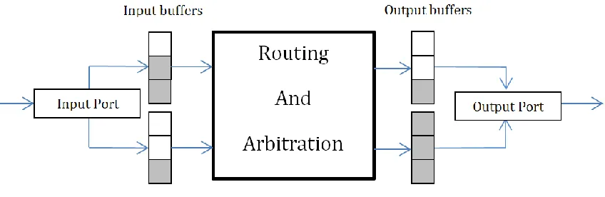
The experiments are carried out using a cycle accurate simulator
implementing the NoC architectures with 3-stage switches namely, input, output
arbitrations and routing [2]. The number of VCs in the CDMA-WiNoC switches
depends on the system size and the number of interconnects. As shown in [30]
irregular networks of size 64, 128 and 256 cores require 4, 6 and 9 layers for
deadlock-free routing. Each layer is considered to have a single VC reserved. The
mesh architecture is considered to have 4 VCs in each input and output port. Each
36
of 32 flits to accommodate simultaneous reception from multiple sources. A uniform
random spatial distribution of traffic is used for the all experiments. All the NoC
components are driven with a 2.5GHz clock. All simulations are performed for ten
thousand cycles allowing for transients to settle in the first few thousand cycles. If
the wireline links are long enough to take more than 1 clock cycle for transmission
of a flit they are pipelined by insertion of FIFO buffers such that between any two
stages it is possible to transfer an entire flit in 1 clock cycle. The on-chip zig-zag
antennas are able to provide a bandwidth of 16GHz around a center frequency of
60GHz [3] while the transceivers [23] are able to sustain a maximum data rate of
6Gbps. All the wireless switches are equipped with the same transceivers.
The Walsh codes result in spreading or widening the spectrum of the
transmitted bits by a spreading factor depending on the number of code chips. We
chose a Walsh code with 8 chips per code resulting is a spreading factor of 8. The
digital decoding technique adopted requires balanced code words where the
number of high and low chips are the same. The number of balanced orthogonal
Walsh codes with 8 chips is 7 [28]. Hence, we can have 7 wireless switches, each
with its unique code for transmission. We have considered a flit size of 32 bits and a
packet size of 64 flits.
The metrics for performance evaluation are maximum achievable bandwidth
and packet energy dissipation. Maximum achievable bandwidth is the peak
sustainable data rate in number of bits successfully routed per second. Bandwidth, B
37
(2)
where, t is the maximum throughput in number of flits received per core per clock
cycle at network saturation, is the number of bits in a flit, N is the number of cores
in the NoC and f is the clock frequency. The throughput is directly obtained from
system level simulations performed by the NoC simulator. The packet energy
dissipation, Epkt is the average energy dissipated in transmission of a packet from
source to destination over the NoC. It can be measured as,
∑ ) )
(3)
Where, Npkt is the number of packets routed in the NoC, Li is the latency of the
ith packet, hi is the number of hops in the path of the packet and Ebuf is the energy
dissipation of a flit in the NoC switch buffers. The energy dissipation of a wireline
hop is Ewire and is the packet length in number of flits. Nsim is the duration of the
simulation and Ewireless is the energy dissipated by all the CDMA transceivers in the
CDMA-WiNoC in one cycle.
As can be seen in (3) the energy dissipation of all the wireless transceivers
for the entire duration of the simulation is considered as an overhead. In addition to
the output power of the transmitter obtained later, the power dissipation of the
CDMA codec, modulator, LNA, mixer and the ADC are also considered while
evaluating Ewireless. The design of a low-power, high-speed ADC with a 5-bit
resolution is proposed in [27]. As noted above the CDMA-WiNoC has 7 wireless
switches and hence, each switch can receive data concurrently from 6 transmitters.
38
switch can be 12 for NRZ data. Therefore, the ADC with 5-bit resolution is enough
for this scenario.
The power dissipation, speed and area overheads of all the components of
the CDMA transceivers are mentioned in table I. The designs of the
modulator/demodulator and the ADC in 65 nm CMOS technology are adopted from
[26] and [27] respectively. The energy dissipation, area overheads and timing
requirements of the NoC switches and the CDMA codecs are obtained from post
synthesis RTL design using 65nm standard cell libraries (http://cmp.imag.fr) using
SynopsysTM tool suites. The energy dissipation of the wireline links are obtained
from Cadence layout tools considering their actual dimensions obtained from
[image:39.612.111.465.421.531.2]assuming a tile-based floorplan of the NoC on a 20mmx20mm die area.
Table 1: Characteristics of the Transceiver Modules
Module Power Dissipation Speed Area
ADC 10.125 mW 12 GS/s 0.055mm2
Modulator/
Demodulator 9.332 mW 6 Gbps 0.34mm
2
CDMA Codec 0.3762 mW 6 GHz 0.0002599mm2
3.8.
Achievable Bandwidth of the CDMA-WiNoC
The peak achievable bandwidth of the CDMA-WiNoC at network saturation
using uniform random traffic for three different system sizes of 64, 128 and 256
39
network saturation for the conventional mesh, small world NoC (SWNoC) and
CDMA-Wireless NoC (WiNoC). The bandwidths are determined according to (2). It
can be seen that the small-world based topologies outperform the conventional
multi-hop wireline mesh significantly. This is because the small-world topology
scales well with increase in size, as the average distance between cores is
significantly less in comparison to regular multi-hop topologies like mesh. The
CDMA-WiNoC performs better than the wireline small-world NoC (SWNoC) due to
the high bandwidth long range CDMA wireless links. The SWNoC architecture is
formed by link insertion following (1) without replacing any long-range wireline
[image:40.612.118.463.364.546.2]link with the wireless links.
Figure 3-4: Peak achievable bandwidth of mesh, SWNoC and CDMA-WiNoCs for 64,128 and 256 core systems
3.9.
Packet Energy Dissipation
In this section the packet energy dissipation of the CDMA-WiNoC is
compared with that of the conventional mesh and wireline small-world NoC for
different system sizes. Figure. 3-5 shows the packet energy dissipation of the
CDMA-0 2 4 6 8 10 12 14
64 128 256
B
and
wi
d
th
(Tbp
s)
System Size(# of cores) mesh
40
WiNoC and the other wireline architectures. The gains in packet energy dissipation
are significant and grow with increase in system size. In a regular multi-hop NoC
like the mesh the packet energy dissipation increases significantly with increase in
system size as packets have to travel over longer distances due to an increase in the
average distance between the cores.
The small-world architecture of the SWNoC and the CDMA-WiNoC are more
scalable as their average distances do not increase significantly. However, the long
wireline links in the SWNoC are very power hungry and result in considerable
energy dissipation. Due to their strategic placement, packets use the long range low
energy wireless links whenever they are traveling between distant cores. Bypassing
the multi-hop long distance wireline paths using the low energy wireless paths
reduce the packet energy dissipation significantly. Although the small-world
connectivity of the SWNoC improves its bandwidth, the data has to travel over long
range wireline links which consumes significant amount of energy limiting the gains
in packet energy dissipation of the SWNoC architecture compared to the
[image:41.612.135.426.539.673.2]CDMA-WiNoC.
Figure 3-5: Packet energy dissipation of mesh, SWNoC and CDMA-WiNoCs for 64,128 and 256 core systems
0 500 1000 1500 2000 2500 3000
64 128 256
Pac
k
et
En
er
gy(
n
J)
41
In figure. 3-6 a detailed breakup of the various components of packet energy
dissipation for the various architectures considered for a 64 core system is shown.
In the SWNoC direct long-range wireline links reduce the energy dissipation in the
switches. However, there is significant energy dissipation in the long wires
increasing the proportion of the energy dissipation in the interconnects. In the
CDMA-WiNoC with uniform random traffic pattern 16.54% packets were routed
over the wireless links. However, these messages are not routed entirely over the
[image:42.612.90.429.196.358.2]wireless links but also consume energy over wireline links and switches. Figure 3-6: Energy breakup comparison for (a) Mesh (b) SWNoC and (c)
CDMA-WiNoC Switch, 39.00% Wire, 61.00% (a) Switch, 4.25% Wire, 95.75% (b) Switch, 3.07% Wire,
96.14% Wireless,
0.79%
(c)
Figure 3-7 : Peak Bandwidth and Packet Energy dissipation comparison of various WiNoCs with 64 cores.
0 0.5 1 1.5 2 2.5 3 3.5 4 0 100 200 300 400 500 600 700 800
SD-MAC T-WiNoC CDMA-WiNoC CNT-WiNoC
B an d wi d th (Tb p s) Pack e t En e rg y(n J)
[image:42.612.120.459.526.671.2]42
Additionally, wireless links dissipate significantly less energy compared to long
wireline links. Consequently, the contribution of the long-range wireless links to
packet energy is much less compared to the wireline counterparts. Higher
bandwidth of the CDMA-wireless links compared to wireline links of the same
length channelizes data through the low-energy wireless links and hence the energy
dissipation per packet is significantly less compared to the wired counterparts.
The figure 3-7 shows a comparative performance evaluation of
CDMA-WiNoC along with other wireless NoC’s like CNT-CDMA-WiNoC and token passing CDMA-WiNoC
(T-WiNoC) for a system size of 64 cores for uniform random traffic pattern. The
peak achievable bandwidth is the maximum for the CNT based WiNoC as the
wireless channels operate at a much higher frequency providing significantly higher
wireless bandwidth compared to the metal antenna based WiNoCs. However,
manufacturing CNT antennas for large-scale production is defect prone and may
result in high rates of failures. The metal antenna based architectures are therefore
readily CMOS manufacturing process compatible and are a more near-term solution
to the problem of soaring energy dissipation in data transfer over a NoC.
Among the metal antenna based architectures the CDMA-WiNoC performs
the best with the highest bandwidth. This is because the SDMAC architecture relies
on multi-hop wireless paths between cores and in the T-WiNoC only a single
wireless link whose transmitter possesses the token is active at any instant of time.
The long range concurrent CDMA based wireless links enhance the performance of
the NoC significantly. Due to higher bandwidth, the packet energy of the
43
3.10.
Performance Evaluation with varying Packet Size
In this section we evaluate the performance of the CDMA-WiNoC by varying
the packet sizes. The performance of the CDMA-WiNoC will differ according the
packet size. Fig. 3-8 shows the performance of a 64 core CDMA-WiNoC for varying
packet size with uniform traffic. The bandwidth decreases as longer packets result
in the network links and buffers being occupied for longer by a particular packet.
The energy per packet increases with increase in packet size as more flits are being
routed over the NoC.
3.11.
Performance Evaluation with Non-Uniform Traffic
In this section we evaluate the performance of the CDMA-WiNoC in presence
of non-uniform traffic patterns. In Fig. 3-9 we present the normalized peak
achievable bandwidth and packet energy dissipation of the CDMA-WiNoC and the
[image:44.612.158.450.322.490.2]wireline SWNoC with 64 cores for non-uniform traffic patterns. The peak bandwidth
Figure 3-8 : Packet Energy dissipation and Throughput comparison of various packet sizes with 64 cores
2.7 2.8 2.9 3 3.1 3.2 3.3 3.4 3.5 3.6 0 50 100 150 200 250 300
32 64 128
B an d wi d th (Tb p s) Pack e t En e rg y(n J)
Packet Size (flits)
44
is normalized with respect to the offered data rate as it varies across the various
traffic patterns. To simulate synthetic traffic we chose hotspot and transpose
distribution patterns. For hotspot traffic all the cores sent 20% of all packets they
generated to an arbitrarily chosen core. The 80% traffic would be uniformly
distributed among the remaining cores. In transpose traffic all cores only send
packets to cores that are diametrically opposite to itself on the die. For all these
traffic patterns the bandwidth and packet energy are evaluated at network
saturation. To model application based traffic, several real benchmarks are
considered. We use GEM5 [31] a full system simulator, to obtain detailed processor
and network-level information. We consider a system of 64 alpha cores running
Linux within the GEM5 platform for all experiments. The memory system is
MOESI_CMP_directory, setup with private 64KB L1 instruction and data caches and
a shared 64MB (1MB distributed per core) L2 cache. Three SPLASH-2 benchmarks,
FFT, RADIX, LU [32], and the PARSEC benchmark CANNEAL [33] are considered.
These benchmarks vary in characteristics from computation intensive to
communication intensive in nature and thus are of particular interest in this work.
The behavior and problem size of the benchmarks is shown in Table 2. One
advantage of the CDMA based WiNoC is its inherent suitability for multicast traffic.
Since, the antennas are not directional they transmit power to all the other
transceivers. Hence we also present results for multicast traffic patterns. For
simulating multicast traffic we consider one core injecting multicast traffic for 3
45
multicast as a case study while the other 50% is considered to be uniformly
distributed unicast traffic.
The advantage of the CDMA-WiNoC over the wireline SWNoC in terms of
packet energy increases with skewed traffic patterns like the hotspot and transpose.
This is because the wireline network is not as efficient as the CDMA-WiNoC in
handling such highly skewed data at high injection loads greater than that causing
network saturation. Also, it is likely that the hotspot is close to a WI enabling
efficient data transfer to the hotspot. The absence of the wireless nodes in the
SWNoC degrades the packet energy significantly more than the CDMA-WiNoC. In
[image:46.612.89.492.141.416.2]case of the application specific benchmarks the offered data injection rate is well
Figure 3-9 : Bandwidth comparison of various non-uniform traffic in CDMA-WiNoC with 64 cores 0 0.2 0.4 0.6 0.8 1 1.2 0 100 200 300 400 500 600 700 800 N o rm al ize d B an d wi d th Pack e t En e rg y(n J) Taffic Patterns
Packet Energy SWNoC Packet Energy CDMA-WiNoC
46
below that of the network saturation. Hence, both the SWNoC and CDMA-WiNoC
perform well under these scenarios. However, the packet energy is still between
13.5 to 43.3 % lower in the CDMA-WiNoC compared to the SWNoC. The maximum
gain is observed for CANNEAL as it is the most communication intensive benchmark
capturing the benefit of the energy-efficient wireless interconnects in the
CDMA-WiNoC the most.
For multicast traffic in the worst case the wireline SWNoC will perform just
like in the unicast case which is shown together with the uniform traffic case in fig.
3-9. This is because the multicast destination may not have any common portion of
their paths from the source. This will cause the multicast traffic to resemble the
unicast traffic. However, in the CDMA-WiNoC the wireless nodes are the multicast
source and destination, the data bandwidth can increase because the single packet
transmitted from the source will be received at multiple destinations. The energy
expenditure remains the same while multiple packets are being delivered over the
wireless channels hence reducing the energy dissipation per packet. However, as we
have considered a single multicast source sending multicast traffic only 50% of the
[image:47.612.133.436.281.386.2]time the overall reduction in packet energy compared to the unicast scenario is only
Table 2: Percentage of busy and idle cycles in a 64-core system given default problem sizes.
Benchmark Busy
% Idle % Default Problem Size
FFT 81.99 18.01 65,536 Data Points
RADIX 84.98 15.02 262,144 Integers, 1024
RADIX
LU 87.62 12.38 512x512 Matrix, 16x16 Blocks
47
5.5%. This will increase with increase in proportion of multicast traffic. It can be
observed from fig. 3-9 that the CDMA-WiNoC outperforms wireline SWNoC for all
the traffic patterns considered here.
3.12.
Area Overheads
In this section we present the area overheads of the transceivers used for all
the wireless NoCs. Table 3 shows the area overheads required by the transceivers
for all the wireless NoCs considered in this work. The transceivers consisting of the
CDMA codec, the modulator/demodulator, the ADC and the wireless ports add area
overheads to the NoC switches with wireless capability. As mentioned earlier, the
area overheads of the NoC switches and the CDMA codecs are obtained from post
synthesis RTL design using 65nm standard cell libraries (http://cmp.imag.fr) using
SynopsysTM tool suites. The area overheads of the modulator/demodulator and ADC
in the CDMA-WiNoC are obtained from [26] and [27] respectively. The area
requirements of these individual modules are mentioned in table I where their
characteristics are shown. The transceiver area for the SD-MAC, T-WiNoC and
CNT-WiNoC are obtained from [9], [25] and [4]. As can be seen the CDMA-CNT-WiNoC has the
least area overhead among all the wireless NoCs except the CNT-WiNoC. This is
because the CNT based transceivers have very small area overhead as the
transceivers only require a few small electro-optic modulators and demodulators.
The CNT-WiNoC, T-WiNoC and the CDMA-WiNoC have a fixed number of WIs and
hence the overhead remains constant with size. However, in the SD-MAC
48
increasing overhead with size. The CDMA-WiNoC uses the least number of WIs
compared to the other WiNoCs using the mm-wave technology and hence has the
least overhead.
Fig. 3-10 shows the area overhead of the various WiNoC architectures for a
system size of 64 cores. The total area overhead of the WiNoCs is due to the area of
the NoC switches and the wireless transceivers. The area of the NoC switches is
nearly same for all the architectures as that depends on the number of ports, which
is the same in all of them. Overheads of the wireless transceivers vary as noted in
table 3. As can be seen from table 3 and fig. 3-10 the wireless transceivers in the
[image:49.612.142.454.171.353.2]CDMA-WiNoC occupy only about 5.52% of the entire die area of 400 mm2.
Figure 3-10: Area overheads of various WiNoCs with 64 cores.
0 10 20 30 40 50 60
CDMA WiNoC SD-MAC T-WiNoC CNT-WiNoC
A
re
a (
sq
. m
m
)
WiNoC Architectures
49
The multi-hop data transfer in traditional wireline NoC networks has high
latency and lower performance. As the system size scales with technology, the
performance of the wireline NoCs and wireless NoCs decreases. The CDMA enabled
wireless communication channels can improve the performance and dissipate lower
energy without compromising the efficiency in data transfer. The CDMA wireless
Network-on-chip architecture outperforms the other wireless NoCs with similar
transceivers and wired counterparts in packet energy and bandwidth. However, all
the transceivers communicate simultaneously through the wireless medium. Due to
the synchronization problem, there is interference between the transceivers which
in turn questions the reliability if the NoC architecture. In the next chapter the
reliability issues of this CDMA based wireless NoC are discussed in detail and
present an analytical model to evaluate the bit error rate (BER) of the wireless
[image:50.612.100.432.86.196.2]channels.
Table 3: Comparison of Area overhead of WiNoCs
System Size
CDMA-WiNoC
(mm2)
SD-MAC
(mm2)
T-WiNoC
(mm2)
CNT-WiNoC
(mm2)
64 22.08 40.96 36.84 0.085
128 22.08 81.92 36.84 0.085
50
Chapter 4.
Reliability analysis of the CDMA WiNoC
Since the transceivers send data simultaneously, at the each receiver, the
wirelessly transmitted CDMA b
![Figure 1-1: Transistor count & Moore’s law (reproduced from [1])](https://thumb-us.123doks.com/thumbv2/123dok_us/43018.3889/13.612.93.487.116.442/figure-transistor-count-moore-s-law-reproduced.webp)


![Figure 3-2: (a) On-chip metal zig-zag antenna(reproduced from [3]) (b) On-chip antenna placement on the die(reproduced from [23])](https://thumb-us.123doks.com/thumbv2/123dok_us/43018.3889/30.612.120.478.344.487/figure-chip-metal-antenna-reproduced-antenna-placement-reproduced.webp)