Frank Thornton
Brad Haines
Francesco Kung Man Fung
John Kleinschmidt
(collectively “Makers”) of this book (“the Work”) do not guarantee or warrant the results to be obtained from the Work.
There is no guarantee of any kind, expressed or implied, regarding the Work or its contents. The Work is sold AS IS and WITHOUT WARRANTY. You may have other legal rights, which vary from state to state. In no event will Makers be liable to you for damages, including any loss of profi ts, lost savings, or other incidental or consequential damages arising out from the Work or its contents. Because some states do not allow the exclusion or limitation of liability for consequential or incidental damages, the above limitation may not apply to you.
You should always use reasonable care, including backup and other appropriate precautions, when working with computers, networks, data, and fi les.
Syngress Media®, Syngress®, “Career Advancement Through Skill Enhancement®,” “Ask the Author UPDATE®,” and “Hack Proofi ng®,” are registered trademarks of Elsevier, Inc. “Syngress: The Defi nition of a Serious Security Library”™, “Mission Critical™,” and “The Only Way to Stop a Hacker is to Think Like One™” are trademarks of Elsevier, Inc. Brands and product names mentioned in this book are trademarks or service marks of their respective companies.
PUBLISHED BY Syngress Publishing, Inc. Elsevier, Inc.
30 Corporate Drive Burlington, MA 01803
How to Cheat at Deploying and Securing RFID
Copyright © 2007 by Elsevier, Inc. All rights reserved. Printed in the United States of America. Except as permitted under the Copyright Act of 1976, no part of this publication may be reproduced or distributed in any form or by any means, or stored in a database or retrieval system, without the prior written permission of the publisher, with the exception that the program listings may be entered, stored, and executed in a computer system, but they may not be reproduced for publication.
Printed in the United States of America 1 2 3 4 5 6 7 8 9 0
ISBN 13: 978-1-59749-230-0
Publisher: Andrew Williams Page Layout and Art: SPi Project Manager: Greg deZarn-O’Hare Cover Designer: Michael Kavish
v
Technical Editors
Francesco Kung Man Fung
(SCJP, SCWCD, SCBCD, ICED, MCP, OCP) has
worked with Java, C#, and ASP.net for 6 years. Mainly, he develops Java-based/.net
fi nancial applications. He loves to read technical books and has reviewed several
certifi cation books.
Fung received a Bachelors and a Master Degree in Computer Science from the
University of Hong Kong.
John Kleinschmidt
is a self-taught, staunch wireless enthusiast from Oxford,
Michigan. John is a security admin for a large ISP in Oakland County, Michigan.
He spends much of his time maintaining personalwireless.org and enjoys reading
up on IT security. John is also a moderator for netstumbler.org.
Contributing Authors
vi
Paul Sanghera
, an expert in multiple fi elds including computer networks
and physics (the parent fi elds of RFID), is a subject matter expert in RFID.
With a Masters degree in Computer Science from Cornell University and
a Ph.D. in Physics from Carleton University, he has authored and co-authored
more than 100 technical papers published in well reputed European and
American research journals. He has earned several industry certifi cations
including CompTIA Network+, CAPM, CompTIA Project+, CompTIA
Linux+, Sun Certifi ed Java Programmer, and Sun Certifi ed Business
Component Developer. Dr. Sanghera has contributed to building world-class
technologies such as Netscape Communicator and Novell’s NDS. He
has taught technology courses at various institutes including San Jose Sate
University and Brooks College. As an engineering manager, he has been at
the ground fl oor of several startups. He is the author of several books on
technology and project management published by publishers such as
McGraw-Hill and Thomson Course Technology.
vii
(ISBN: 1-931836-31-0). He resides in Vermont with his wife.
Anita Campbell
is a consultant, speaker, and writer who closely follows
trends in technology, including the development of the RFID market.
She writes for a number of publications, and serves as the Editor for
the award-winning RFID Weblog, named to the CNET Blog 100, and
syndicated on MoreRFID.com. She is a part-time instructor at the
University of Akron and is also the host of her own talk radio program/
podcast series on the VoiceAmerica.com Internet radio network.
Anita has held a variety of senior executive positions culminating in
the role of CEO of an information technology subsidiary of Bell & Howell.
She also has served on a number of Boards, including Vice Chair of the
Advisory Board, Center for Information Technology and eBusiness at the
University of Akron. Anita holds a B.A. from Duquesne University and
a J.D. from the University of Akron Law School.
Brad ‘RenderMan’ Haines
is one of the more visible and vocal members
of the wardriving community, appearing in various media outlets and
speaking at conferences several times a year. Render is usually near by on
any wardriving and wireless security news, often causing it himself. His
skills have been learned in the trenches working for various IT companies
as well as his involvement through the years with the hacking community,
sometimes to the attention of carious Canadian and American intelligence
agencies. A fi rm believer in the hacker ethos and promoting responsible
hacking and sharing of ideas, he wrote the ‘Stumbler ethic’ for beginning
wardrivers and greatly enjoys speaking at corporate conferences to dissuade
the negative image of hackers and wardrivers.
His work frequently borders on the absurd as his approach is usually
one of ignoring conventional logic and just doing it. He can be found in
Edmonton, Alberta, Canada, probably taking something apart.
viii
INCITS T20 RTLS committee for global RFID and wireless standards
development. He formulated the product strategy for AdaptLink™, the
pioneer RFID middleware product, and led successful enterprise wide
deployments including a multi-site rollout in the Air Force supply chain.
Previously he was Vice President with SAIC where he led the RFID
practice across several industry verticals and completed global rollouts
of RFID infrastructure across America, Asia, Europe and South Africa.
He served as the corporate contact for VeriSign and played a key role in
shaping the EPCglobal Network for federal and commercial corporations.
Earlier, he was chief architect at BEA systems responsible for conceptualizing
and building the Weblogic Integration suite of products. He has been a
signifi cant contributor to ebXML and RosettaNet standard committees
and was the driving force behind the early adoption of service-oriented
architecture. Anand has held senior management positions at Vitria, Tibco,
Adept, Autodesk and Intergraph.
Anand has Bachelor of Technology (Honors) from IIT Kharagpur
and Master of Science from Columbia University with specialization in
computer integrated manufacturing. He served as the past chairman of
NVTC’s ebusiness committee and is a charter member of TIE Washington,
DC. Anand and his wife, Annapurna, and their two children live in
Mclean, VA.
Contents
ix
Chapter 1 Physics, Math, and RFID: Mind the Gap . . . .1
Introduction . . . 2
Some Bare-Bones Physics Concepts . . . 2
Understanding Electricity . . . 4
Understanding Magnetism . . . 6
Understanding Electromagnetism . . . 7
Electromagnetic Waves . . . 8
Types of Electromagnetic Waves . . . 9
The Electromagnetic Spectrum . . . 10
The Mathematics of RFID . . . 11
Scientifi c Notation . . . 11
Logarithms . . . 12
Decibel . . . 13
Units . . . 14
An Overview of RFID: How It Works . . . 15
Summary . . . 21
Chapter 2 The Physics of RFID . . . .23
Introduction . . . 24
Understanding Radio Frequency Communication . . . 24
Elements of Radio Frequency Communication . . . 24
Modulation: Don’t Leave Antenna Without It . . . 26
The Propagation Problem . . . 26
The Transmission Problem . . . 26
Frequency Bands in Modulation . . . 26
Understanding Modulation Types . . . 27
Amplitude Modulation and Amplitude Shift Keying . . . 27
Frequency Modulation and Frequency Shift Keying . . . 30
Phase Modulation and Phase Shift Keying . . . 32
On-Off Keying (OOK) . . . 32
RFID Communication Techniques . . . 33
Communication Through Coupling . . . 33
Communication Through Backscattering . . . 34
Understanding Performance Characteristics of an RFID System . . . 35
Cable Loss . . . 35
Impedance . . . 35
The Voltage Standing Wave Ratio . . . 36
Noise . . . 37
Beamwidth . . . 38
Antenna Gain . . . 39
Polarization . . . 40
Resonance Frequency . . . 41
Performing Antenna Power Calculations . . . 42
Effective Radiated Power . . . 42
Power Density . . . 42
Link Margin. . . 43
The Travel Adventures of RF Waves . . . 43
Absorption . . . 43
Attenuation . . . 44
Dielectric Effects . . . 44
Diffraction . . . 44
Free Space Loss . . . 44
Interference . . . 45
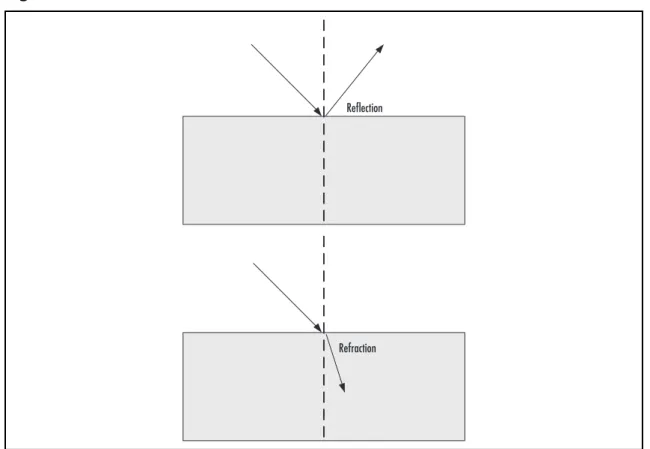
Refl ection . . . 45
Refraction . . . 45
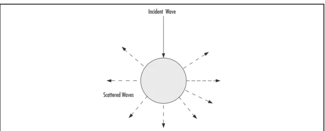
Scattering . . . 46
Summary . . . 48
Key Terms . . . 49
Chapter 3 Working with RFID Tags . . . .51
Introduction . . . 52
Understanding Tags . . . 52
Components of a Tag . . . 52
Tag Size . . . 55
Operating Tag Frequencies . . . 55
Understanding Tag Types . . . 57
Passive Tags . . . 57
Semipassive Tags . . . 58
Active Tags . . . 59
Tag Classifi cation . . . 61
Class 0 Tags . . . 62
Class 1 Tags . . . 63
Class 2 Tags . . . 63
Class 3 Tags . . . 64
Class 4 Tags . . . 64
Class 5 Tags . . . 64
Read Ranges of Tags . . . 66
Labeling and Placing a Tag . . . 67
Labeling a Tag . . . 67
Inlay . . . 68
Insert . . . 68
Smart Labels. . . 68
Pressure-Sensitive Labels . . . 69
RFID-Enabled Tickets . . . 69
Tie-On Tags . . . 69
Placing a Tag . . . 70
Shadowing . . . 71
Tag Placement and Orientation . . . 72
Polarization and Orientation . . . 72
Orientation in Inductive Coupling . . . 73
Summary . . . 74
Key Terms . . . 75
Chapter 4 Working with Interrogation Zones . . . .77
Introduction . . . 78
Understanding an Interrogator . . . 78
What an Interrogator Is Made Of . . . 79
Interrogator Types . . . 79
Fixed-Mount Interrogators . . . 80
Handheld Interrogators . . . 80
Vehicle-Mount Interrogators . . . 81
What an Interrogator Is Good For . . . 81
Communication With the Host Computer . . . 81
Communication With the Tags . . . 82
Operational Capabilities . . . 82
Communicating With the Host . . . 83
Serial Connections . . . 83
Network Connections . . . 84
Dealing With Dense Environments . . . 86
Understanding Collisions . . . 86
Reader Collisions . . . 86
Tag Collisions . . . 87
Anticollision Protocols . . . 87
Aloha-Based Protocols . . . 87
Tree-Based Protocols . . . 88
Confi guring Interrogation Zones . . . 88
Confi guring Interrogator Commands . . . 89
Confi guring Interrogator Settings . . . 91
Optimizing Interrogation Zones . . . 92
The Network Factor . . . 92
Operation Mode . . . 93
Reader-to-Reader Interference . . . 93
System Performance and Tuning . . . 94
The Tag Travel Speed . . . 94
Summary . . . 96
Key Terms . . . 97
Chapter 5 Working with Regulations and Standards . . . .101
Introduction . . . 102
Understanding Regulations and Standards . . . 102
Regulations . . . 102
Regulating Frequency Usage . . . 103
The Regulatory Regions . . . 104
Safety Regulations . . . 105
RFID Standards . . . 107
ISO Standards . . . 107
EPCglobal Standards . . . 108
Air Interface and Tag Data Standards . . . 111
Tag Data Standards . . . 111
Air Interface Protocols . . . 111
Impact of Regulations and Standards . . . 112
Advantages of Regulations . . . 112
Advantages of Standards . . . 112
Disadvantages of Regulations and Standards . . . 113
Regulatory and Standards Bodies. . . 113
Summary . . . 115
Key Terms . . . 116
Chapter 6 Selecting the RFID System Design . . . .119
Introduction . . . 120
Understanding RFID Frequency Ranges . . . 120
RFID Frequency Ranges and Performance . . . 122
The Low-Frequency (LF) Range . . . 123
The High-Frequency (HF) Range . . . 124
Ultra High Frequency (UHF) Range . . . 124
The Microwave Range . . . 125
Selecting Operating Frequency . . . 127
Selecting Tags . . . 128
Kinds of Tag . . . 128
Tag Types . . . 128
Tag Classes . . . 128
Operating Frequency . . . 129
Read Performance . . . 129
Data Capacity . . . 130
Tag Form and Size . . . 130
Environmental Conditions . . . 131
Standards Compliance . . . 131
Selecting Readers . . . 131
Reader Types . . . 131
Ability to Upgrade . . . 132
Installation Issues . . . 132
Legal Requirements . . . 132
Manageability . . . 133
Quantity . . . 133
Ruggedness . . . 133
Working With Antennas . . . 133
Understanding Antenna Types . . . 133
Monopole Antennas . . . 135
Linearly Polarized Antenna . . . 135
Circularly Polarized Antennas . . . 136
Omnidirectional Antennas . . . 137
Helical Antennas . . . 137
Selecting Antennas . . . 137
Selecting Transmission Lines . . . 138
Impedance . . . 138
Cable Length and Loss . . . 138
Transmission Line Types . . . 139
Mounting Equipment for RFID Systems . . . 139
Conveyors . . . 140
Dock Doors . . . 141
Forklifts . . . 141
Stretch Wrap Stations . . . 142
Point-of-Sale Systems . . . 142
Smart Shelf . . . 143
Summary . . . 144
Key Terms . . . 145
Chapter 7 Performing Site Analysis . . . .147
Introduction . . . 148
Planning the Site Analysis . . . 148
Plan the Steps Ahead . . . 148
Understanding Blueprints . . . 149
Performing a Physical Environmental Analysis . . . 150
Harsh Environmental Conditions . . . 150
Physical Obstructions . . . 151
Metallic Material . . . 151
Packaging . . . 151
Cabling . . . 151
Electrostatic Discharge . . . 151
Performing an RF Environmental Analysis . . . 152
Planning a Site Survey . . . 153
Determining the Ambient EM Noise . . . 154
Analyzing the Electrical Environmental Conditions . . . 156
Protecting the RFID System from Interference and Noise . . . 156
Preparing Your Own Blueprints . . . 157
Let the Experiment Begin . . . 157
Using the Results of Your Experiment . . . 159
Summary . . . 160
Key Terms . . . 161
Chapter 8 Performing Installation . . . .163
Introduction . . . 164
Preparing for Installation . . . 164
Considering Power Sources . . . 166
Batteries . . . 166
Power Supply Units . . . 167
Uninterruptible Power Supplies . . . 167
Power Over Ethernet . . . 167
The Standard Installation Process and Practices . . . 168
Design Selection. . . 168
Site Analysis . . . 168
Installation Tasks . . . 168
System Management . . . 169
The Tag Thing . . . 170
Installing Hardware . . . 170
Installing Readers . . . 171
Installing Antennas . . . 171
Installing Cables . . . 172
Testing During Installation . . . 172
Interrogation Zone Tests . . . 172
Unit Tests . . . 173
Application Integration Tests . . . 173
System Tests . . . 173
Ensuring Safety . . . 174
Equipment Safety from the Environment . . . 174
Electrostatic Discharge . . . 175
Grounding . . . 176
Ground Loops . . . 177
Safety Regulations . . . 177
Working With Various Installation Scenarios . . . 177
Setting Up Stationary Portals . . . 178
Setting Up a Conveyor Portal . . . 178
Setting Up a Dock Door Portal . . . 180
Setting Up a Shelf Portal . . . 181
Setting Up Mobile Portals . . . 183
Handheld Interrogator Portals . . . 183
Mobile-Mount Portals . . . 183
Summary . . . 185
Key Terms . . . 186
Chapter 9 Working With RFID Peripherals . . . .187
Introduction . . . 188
Smart Labels: Where RFID Meets Barcode . . . 188
Working With RFID Printers . . . 189
Understanding RFID Printers . . . 190
Installing the RFID Printer . . . 193
Confi guring the RFID Printer . . . 195
Troubleshooting the RFID Printer . . . 197
Understanding Ancillary Devices and Concepts . . . 201
RFID Printer Encoders . . . 201
Automated Label Applicators . . . 202
Pneumatic Piston Label Applicators . . . 202
Wipe-On Label Applicators . . . 203
Feedback Systems. . . 205
Photo Eyes . . . 206
Light Trees . . . 206
Horns . . . 207
Motion Sensors . . . 208
Real-Time Location Systems . . . 208
Summary . . . 211
Key Terms . . . 212
Chapter 10 Monitoring and Troubleshooting RFID Systems . . . .215
Introduction . . . 216
Monitoring an RFID System . . . 216
Understanding Root-Cause Analysis . . . 216
Understanding Monitoring . . . 219
Status Monitoring . . . 219
Performance Monitoring . . . 220
Monitoring and Troubleshooting Interrogation Zones . . . 220
Mean Time Between Failures (MTBF) . . . 220
Average Tag Traffi c Volume . . . 221
Actual Versus Predicted Traffi c Rate . . . 222
Read Errors to Total Reads Rate . . . 223
Read Error Change Rate . . . 223
Monitoring and Troubleshooting Tags . . . 224
Identifying Improperly Tagged Items . . . 224
Identifying Reasons for Tag Failures . . . 225
Managing Tag Failures . . . 226
Management Prior to Applying Tags . . . 226
Management During Application . . . 227
Management After Applying the Tags/During Tracking . . . 227
Monitoring and Troubleshooting Hardware . . . 228
Understanding the Causes of Hardware Failures . . . 228
Diagnosing RFID Hardware Failures . . . 229
Standard Troubleshooting Procedure . . . 230
Summary . . . 232
Key Terms . . . 233
Chapter 11 Threat and Target Identifi cation . . . .235
Introduction . . . 236
Attack Objectives . . . 236
Radio Frequency Manipulation . . . 237
Spoofi ng . . . 237
Insert . . . 237
DOS . . . 238
Manipulating Tag Data . . . 238
Middleware . . . 239
Backend . . . 240
Blended Attacks . . . 241
Summary . . . 242
Chapter 12 RFID Attacks: Tag Encoding Attacks . . . .243
Introduction . . . 244
Case Study: John Hopkins vs. SpeedPass. . . 244
The SpeedPass . . . 244
Breaking the SpeedPass . . . 248
The Johns Hopkins Attack . . . 250
Lessons to Learn . . . 253
Summary . . . 256
Chapter 13 RFID Attacks: Tag Application Attacks . . . .257
MIM 258 Chip Clones - Fraud and Theft . . . 258
Tracking: Passports/Clothing . . . 262
Passports . . . 264
Chip Cloning > Fraud . . . 266
Disruption . . . 268
Summary . . . 269
Chapter 14 RFID Attacks: Securing Communications Using RFID Middleware . . . .271
RFID Middleware Introduction . . . 272
Electronic Product Code System Network Architecture . . . 272
EPC Network Software Architecture Components . . . 272
Readers . . . 272
RFID Middleware . . . 273
EPC Information Service . . . 273
Object Name Service . . . 274
ONS Local Cache . . . 274
EPC Network Data Standards . . . 274
EPC . . . 275
PML . . . 275
RFID Middleware Overview . . . 275
Reader Layer—Operational Overview . . . 277
Smoothing and Event Generation Stage . . . 280
Event Filter Stage . . . 280
Report Buffer Stage . . . 280
Interactions with Wireless LANs . . . 281
802.11 WLAN . . . 281
Attacking Middleware with the Air Interface . . . 283
Understanding Security Fundamentals and Principles of Protection. . . 287
Understanding the Role of Encryption in RFID Middleware . . . 288
Overview of Cryptography . . . 288
Symmetric Ciphers . . . 289
Asymmetric Ciphers . . . 291
Elliptic Curve Ciphers . . . 292
Understanding How a Digital Signature Works . . . 292
Basic Digital Signature and Authentication Concepts . . . 293
Why a Signature Is Not a MAC . . . 293
Public and Private Keys . . . 293
Why a Signature Binds Someone to a Document . . . 294
Learning the W3C XML Digital Signature . . . 294
Applying XML Digital Signatures to Security . . . 297
Using Advanced Encryption Standard for Encrypting RFID Data Streams . . . 298
Addressing Common Risks and Threats . . . 298
Experiencing Loss of Data . . . 299
Loss of Data Scenario . . . 299
The Weaknesses in WEP . . . 299
Criticisms of the Overall Design . . . 300
Weaknesses in the Encryption Algorithm . . . 300
Weaknesses in Key Management . . . 301
Securing RFID Data Using Middleware . . . 302
Fields: . . . 302
Using DES in RFID Middleware for Robust Encryption . . . 303
Using Stateful Inspection in the Application Layer Gateway For Monitoring RFID Data Streams . . . 305
Application Layer Gateway . . . 305
Providing Bulletproof Security Using Discovery, Resolution, and Trust Services in AdaptLink™ . . . 306
Discovery Service . . . 306
Resolution, ONS, and the EPC Repository . . . 307
EPC Trust Services . . . 307
Summary . . . 309
Chapter 15 RFID Security: Attacking the Backend . . . .311
Introduction . . . 312
Overview of Backend Systems . . . 312
Data Attacks . . . 314
Data Flooding . . . 314
Problem 1 . . . 314
Solution 1 . . . 314
Problem 2 . . . 314
Solution 2 . . . 314
Purposeful Tag Duplication. . . 315
Problem . . . 315
Solution . . . 315
Problem . . . 315
Solution . . . 315
Readability Rates . . . 315
Problem . . . 315
Solution . . . 316
Virus Attacks . . . 316
Problem 1 (Database Components) . . . 316
Problem 2 (Web-based Components) . . . 316
Problem 3 (Web-based Components) . . . 316
Solution 1 . . . 317
Problem 4 (Buffer Overfl ow) . . . 317
Solution 4 . . . 317
RFID Data Collection Tool - Backend Communication Attacks . . . 317
MIM Attack . . . 317
Application Layer Attack . . . 317
Solution . . . 318
TCP Replay Attack . . . 318
Solution . . . 318
Attacks on ONS . . . 318
Known Threats to DNS/ONS . . . 318
ONS and Confi dentiality . . . 319
ONS and Integrity. . . 319
ONS and Authorization . . . 319
ONS and Authentication . . . 320
Mitigation Attempts . . . 320
Summary . . . 321
Chapter 16 Management of RFID Security . . . .323
Introduction . . . 324
Risk and Vulnerability Assessment . . . 324
Risk Management . . . 326
Threat Management . . . 328
Summary . . . 331
1
Chapter 1
Physics, Math,
and RFID: Mind
the Gap
Solutions in this chapter:
■
Some Bare-Bones Physics Concepts
■
Understanding
Electricity
■
Understanding
Magnetism
■
Understanding
Electromagnetism
■
The Mathematics of RFID
■
An Overview of RFID: How It Works
Introduction
What do the U.S. Department of Defense, Wal-Mart, and you have in common? Radio
frequency identifi cation, or RFID! Whether you choose to know about it or not, RFID
affects you and the world around you in a ubiquitous way. So, congratulations that you have
chosen to learn about it.
The fi rst thing to understand about RFID is that it is an application of physics to the
extent that the core functioning of RFID technology is governed by the laws of physics. You
don’t need to have a Ph.D. in physics to become a successful RFID professional, but an
understanding of the physics of RFID will enable you to design, deploy, and operate RFID
systems in an optimal way. In this chapter, we attempt to ease your way into physics as it
relates to RFID by explaining some basic physics concepts. As they say, mathematics is the
language of physics, or of any science for that matter. The good news is that you need only
very simple math to understand RFID: powers of 10, logarithms, and some unit conversions.
Before you dive into the book, we take a bird’s-eye view of RFID in this chapter. The goal
is to provoke you to start asking questions about the details that will be addressed in the
forthcoming chapters.
The overall goal of this chapter is to help you avoid falling into the gaps between physics,
math, and RFID. We fi ll those gaps by exploring three avenues: basic physics concepts, the
math of RFID, and an overview of RFID.
Some Bare-Bones Physics Concepts
Just when you thought you got away with missing physics classes in high school, here comes
a physics lecture for you! But fear not. It’s going to be very simple and concise.
As you already know, physics is a discipline in natural science. The word science has its
origin in a Latin word that means to know. Science is the body of knowledge of the natural
world, organized in a rational and verifi able way. The word physics has its origin in the Greek
word that means nature. Physics is that branch (or discipline) of science that deals with
understanding the universe and its systems in terms of fundamental constituents of matter
(such as atoms, electrons, and quarks) and the interactions among those constituents. Applied
physics refers to the practical (such as technological) use of physics—for example, electronics,
engineering, and RFID. In other words, applied physics involves utilizing basic physics
principles to build practical devices and systems such as radios, televisions, cellular phones,
or an RFID system.
To clear your way toward understanding the physics behind RFID, let’s look at some
basic physics concepts:
of physics are expressed in terms of relationships among the physical quantities.
Length, time, speed, force, energy, and temperature are some examples of
physical quantities.
■
Unit
A physical quantity is measured in numbers of a basic amount called a unit.
The measurement of a quantity contains a number and a unit—for example, in
15 miles, mile is a unit of distance (or length).
■
Force
This is the infl uence that an object exerts on another object to cause some
change.
■
Interaction
This is a mutual force between two objects through which they
affect each other. For example, two particles attract each other or repel each
other. Sometimes the words interaction and force are used synonymously. There are
four known basic interactions (or forces) that keep the universe functioning
together:
■
Gravitational
force
■
Electromagnetic force
■
Strong nuclear force
■
Weak nuclear force
Where there is a force, there is energy, or potential for energy.
■
Energy
Energy is the measure of the ability of a force to do work. There are different
kinds of energies corresponding to different forces, such as electromagnetic
energy.
■
Power
Power is the amount of work done or the energy trasnsferred per unit
time.
■
Work
Work is a measure of the amount of change produced by a force acting on
an object. But how is it possible that two charged objects separated from each other
can exert force on each other? This is where the concept of fi eld comes into the
picture.
■
Speed
Speed, in general, means the rate of something. In physics, it means the
rate of motion; for example, your car is moving at a speed of 70 miles per hour.
■
Hypothesis
A hypothesis is a principle-like statement made as an explanation of
a phenomenon and is generally based on previous observations, extensions of
existing scientifi c theories, or both. The scientifi c method requires that a scientifi c
hypothesis must be verifi able; that is, you must be able to test it. The word hypothesis
has its roots in the Greek word that means to suppose.
■
Law
A physics law (also called a physical law, a law of nature, or a scientifi c law) is
a set of generalized conclusions based on observations of physical behavior through
repeated scientifi c experiments, and these conclusions are generally accepted within
the scientifi c community. A hypothesis may turn into a law through repeated
confi rmation by scientifi c experiments.
Of the four basic interactions in the universe, the interaction that is relevant to RFID is
the electromagentic interaction, which exhibits itself in our world in many forms, including
electricity and magnetism.
Understanding Electricity
Electricity is the property of matter related to electric charge. Historically, the word
electricity has been used by several scientists to mean electric charge. This property
(electricity) is responsible for several natural phenomena such as lightning and is used
in several industrial applications such as electric power and the whole field of
electronics.
To understand electricity, you must understand the related concepts discussed in the
following:
Electric charge
Electric charge, also referred to simply as charge, is a basic
property of some fundamental particles of matter. There are two types of
charge: positive and negative. For example, an electron has a negative charge,
and a positron (an anti-particle of electron) has a positive charge. The standard
symbol used to represent charge is q or Q. Two particles (or objects) with the
same type of charge repel each other, and two objects with the opposite types
of charge attract each other. The charge is measured in units of coulomb,
denoted by C.
Capacitance
This is the amount of charge stored in a system, called a capacitor,
per unit of electric potential. In other words, the capacitance, C, is defi ned by the
following equation:
C = Q/V
One example of a capacitor is the so-called parallel plates capacitor: two metallic
plates separated from each other, with each plate carrying equal and opposite
charge, Q, with a potential difference between them, V. Capacitance is measured in
units of farad, denoted by F. For example, if the charge on each plate of a parallel
plate capacitor is one C, and the voltage between them is one V, the capacitance of
the capacitor will be one F.
Electric current
This is the rate of fl ow of electric charge per unit time and can
be defi ned by the following equation:
I = Q/t
In this equation, I is the current and Q is the amount of charge that fl owed past a
point in time t. Current is measured in units of ampere, denoted by A. For example,
one C of charge fl owing past a point in one second represents one A of current.
The material such as metals that permit relatively free fl ow of charge are called
conductors, whereas the materials such as glass that do not allow free fl ow of charge
are called insulators.
Resistance
This is a measure of opposition offered by a material to the flow
of charge through it. The resistance can be measured by the following
equation:
I = V/R
This means the larger the resistance, the smaller the current. Resistance is
measured in units of ohm, denoted by . For example, if the voltage of one V
creates one A of current in a conductor, then the resistance of the conductor
is one .
Electric energy
This is the amount of work that can be done by an amount of
electric charge across a potential difference. For example, the energy, E, of a charge
Q across a voltage V is given by the following equation:
E = QV
Electric power
This is the rate of work performed by an electric current. In
other words, it’s the electric energy produced or consumed per unit of time, and is
given by the following equation:
The power is measured in units of watt (W
). For example, the power consumed to
maintain a current of one A across a voltage of one V is one W.
Electric fi eld
Electric
fi eld is a fi eld that charges at a distance used to exert force
on each other. In other words, the charges at a distance interact with each other
through their fi elds, called electric fi elds.
Two charges of the same type exert repulsive force on each other, and two charges
of opposite types exert attractive force on each other, and this force is called electric
force. A charge in motion creates another kind of force, called magnetic force.
Understanding Magnetism
Magnetism is the property of material that enables two objects to exert a specifi c kind of
force on each other, called magnetic force, which is created by electric charge in motion. To
understand magnetism, you must understand the related concepts discussed in the following:
Magnetic fi eld
A
magnetic
fi eld is a fi eld produced by a moving charge that it
uses to exert magnetic force on another moving charge.
Confi guring & Implementing…
Show that electric power can also be expressed by the following equations: P = I2R
P = V2/R
Solution: We know that: P = IV
We also know that: I = V/R
Therefore:
P = IV = (V/R)V = V2/R But:
I = V/R means V = IR Therefore:
Magnetic fl ux
This is a measure of the quantity of magnetic fi eld through a
certain area. It is proportional to the strength of the magnetic fi eld and the surface
area under consideration. For example, the current running through a wire in a
circuit will create the magnetic fi eld and hence the magnetic fl ux in the area
around it.
Faraday’s Law
Faraday’s Law states that the change in magnetic fl ux creates
electromotive force, which is practically a voltage. In other words, the changing
magnetic fl ux through a circuit will induce a current in the circuit. Recall that the
magnetic fl ux can be created by the current in a circuit. Faraday’s Law says the
reverse: The change in fl ux can create current.
Inductive coupling
Consider two electric circuits next to each other. There will
be magnetic fl ux through the second circuit due to the current in the fi rst circuit.
If you change the current in the fi rst circuit, it will change the magnetic fl ux
through the second circuit, and the change in magnetic fl ux will create the current
through the second circuit due to Faraday’s Law. This effect, called inductive coupling,
is used in RFID systems. You will see in this book that readers use inductive coupling
to communicate with passive tags in an RFID system. You will be introduced to
readers and tags later in this chapter.
Electricity and magnetism are related to each other and can be looked upon as two facets
of what is called electromagnetism.
Understanding Electromagnetism
Electromagnetism is the unifi ed framework through which to understand electricity, magnetism,
and the relationship between them—in other words, to understand electric fi elds and magnetic
fi elds and the relationship among them. To see the relationship, fi rst recall that a charge creates
an electric fi eld and that when the same charge starts moving, it creates a magnetic fi eld.
The electric fi eld exerts electric force, whereas a magnetic fi eld exerts magnetic force; both
originate from the electric charge. Therefore, they are intimately related: A changing electric
fi eld produces a magnetic fi eld, and a changing magnetic fi eld produces an electric fi eld.
Due to this intimacy, the electric force and magnetic force are considered two different
man-ifestations of the same unifi ed force, called electromagnetic (EM) force. The unifi ed form of the
electric fi eld and magnetic fi eld is called an electromagnetic fi eld, and the electric fi eld and the
magnetic fi eld are considered its components. In other words, electromagnetic force is
exerted by an electromagnetic fi eld.
Electromagnetic Waves
A wave is a disturbance of some sort that propagates through space and transfers some kind
of energy from one point to another. For example, when you speak to a person face to face,
the sound wave travels from your mouth to the ear of the listener. The “disturbance” here is
the change of pressure in the air. As long as the wave is traveling through a point, the air
pressure at that point does not stay constant over time. The disturbance in an electromagnetic
fi eld is the change of electric and magnetic fi eld. The wave can be looked upon as propagation
of this disturbance.
As shown in Figure 1.1, you can describe a wave in terms of some parameters such as
amplitude, frequency, and wavelength.
■
Wavelength
Denoted by the symbol , this is the distance between two
consecutive crests or two consecutive troughs of a wave. The distance equal to
wavelength makes one cycle of change.
■
Amplitude
Amplitude is the maximum amount of disturbance during one wave
cycle.
■
Frequency
This is the number of cycles per unit of time a wave repeats. The
frequency of an electromagnetic wave, f, propagating through free space (a vacuum),
is calculated using the following equation:
f = c/
c is the velocity of light in vacuum. The frequency is measured in units of
Hertz. One cycle per second is one Hertz, denoted by Hz.
■
Phase
This is the current position in the cycle of change in a wave.
So, what is the frequency of EM waves? EM waves cover a wide spectrum of frequencies,
and the ranges of these frequencies constitute one way we defi ne different types of EM waves.
A
Distance Disturbance
=Wavelength A=Amplitude
Types of Electromagnetic Waves
Electromagnetic waves can be grouped according to the direction of disturbance in them
and according to the range of their frequency. Recall that a wave transfers energy from one
point to another point in space. That means there are two things going on: the disturbance
that defi nes a wave, and the propagation of wave. In this context the waves are grouped into
the following two categories:
■
Longitudinal waves
A wave is called a longitudinal wave when the disturbances
in the wave are parallel to the direction of propagation of the wave. For example,
sound waves are longitudinal waves because the change of pressure occurs parallel
to the direction of wave propagation.
■
Transverse waves
A wave is called a transverse wave when the disturbances in
the wave are perpendicular (at right angles) to the direction of propagation of
the wave.
Electromagnetic waves are transverse waves. That means the electric and magnetic fi elds
change (oscillate) in a plane that is perpendicular to the direction of propagation of the wave.
Also note that electric and magnetic fi elds in an EM wave are also perpendicular to each other.
N
OTEElectric fi elds and magnetic fi elds (E and B) in an EM wave are perpendicular to each other and are also perpendicular to the direction of propagation of the wave.
Because electric and magnetic fi elds change in a plane (perpendicular to the direction
of wave propagation), the direction of change still has some freedom. Different ways of
using this freedom provide another criterion to classify electromagnetic waves into the
following:
■
Linearly polarized waves
If the electric fi eld (and hence the magnetic fi eld)
changes in such a way that its direction remains parallel to a line in space as the
wave travels, the wave is called linearly polarized.
C
AUTIONOnly transverse waves can be polarized, because in a longitudinal wave, the disturbance is always parallel to the direction of wave propagation.
As shown in Figure 1.2, the radio waves occupy a major part of the electromagnetic
spectrum. As the name suggests, a radio frequency identifi cation (RFID) system uses radio
waves to communicate.
If the numbers in Figure 1.2 do not make sense to you and if you have forgotten all
about scientifi c notation, units of measurement, and logarithms, you will need to brush up
on these math-related concepts to make your journey through this book smoother.
So, you can classify electromagnetic waves based on the direction of disturbance in them
(polarization). The other criterion to classify EM waves is the frequency.
The Electromagnetic Spectrum
Have you ever seen electromagnetic waves with your naked eye? The answer, of course, is
yes! Visible light is an example of electromagnetic waves. In addition to visible light,
electro-magnetic waves include radio waves, ultraviolet radiation, and X-rays (which of course are
not visible to the naked eye). These different kinds of EM waves only differ in their frequency
and therefore their wavelength. The whole frequency range of EM waves is called the
electromagnetic spectrum, which is illustrated in Figure 1.2, along with the names associated
with different frequency ranges within the spectrum.
Figure 1.2
The Electromagnetic Spectrum1 km 1 10
-2
103 10-6 10-9 10-12
10 102 103 104 105 106 107 108 109 1010 1011 1012 1013 1014 1015 1016 1017 1018 1019 1020
107 10-3 10-4
Radio Waves Infrared Radiation Visible Light Ultraviolet Radiation
X Rays and Gamma Rays
Frequency (HZ)
Wavelength (m)
The Mathematics of RFID
This section discusses some math-related concepts such as scientifi c notation, units, and
logarithm. Understanding these concepts will help you more fi rmly grasp the concepts
discussed throughout this book.
Scientifi c Notation
To express numbers, scientists use a notation called scientifi c notation. It simplifi es handling
very large and very small numbers. Using this notation, you express a number as a product
of a number between 1 and 10 and a power of 10. For example, the number 174,000 is
expressed in scientifi c notation as:
1.74 × 10⁵
To convert a number in scientifi c notation to the ordinary notation, here is the rule:
Count as many places as the power of 10 after the decimal point, replace any empty place
with a 0, and remove the point. For example:
1.25 × 104 = 12500
104 = 1 × 104 = 10000
Some powers of 10 have a name called a prefi x. For example, 10
3is called kilo, as in
kilometer or kilogram. These powers of 10 in common use are shown in Table 1.1, along
with the numbers they represent.
Table 1.1 Prefi xes for Powers of 10
Power of 10 Number Prefi x Abbreviation
1012 1000,000,000,000 Tera T
109 1000,000,000 Giga G
106 1000,000 Mega M
103 1000 Kilo k
10−1 1/10 Deci d
10−2 1/100 Centi c
10−3 1/1000 Milli m
10−6 1/1000,000 Micro
10−9 1/1000,000,000 Nano n
N
OTEThe power of 10 is also called exponent. For example, in 103, the number 3 is an exponent. In general, a mathematical operation written as xn is called
“x raised to the power n.” This is also called exponentiation, with x as a base and n as an exponent.
In general, a
xis called an exponential function. It means multiply the base with itself as many
times as the exponent. For example:
23 = 2 * 2 * 2 = 8
Remember the following two formulae for exponential functions. The fi rst formula is:
ax * ay = ax y
For example:
22 * 23 = 25 = 2 * 2 * 2 * 2 * 2 = 32
The second formula is:
ax/ay = ax-y
For example:
25/23 = 22 = 2 * 2 = 4
In addition to exponentiation, there is another function relevant to this book: the
logarithmic function.
Logarithms
Logarithm is the inverse of an exponential function:
y = ax => x = log ay
The expression log
ay is read as log y to the base a. For example:
1000 = 103 => 3 = log 10 1000
The base 10 is a default for the term log; that is, log (1000) means log of 1000 to the base
10. After understanding the defi nition of log, you need to remember three more formulae
for the log function. The fi rst formula is:
For example:
log 1000 = log 103 = 3 * log 10
The second formula is:
log (x*y) = log x + log y
For example:
log 1000 = log(10*100) = log 10 + log 100
The third formula is:
log (x/y) = log x log y
For example:
log 100 = log(10000/100) = log 10000 − log 100
An example of use of your knowledge of logarithm is the decibel unit.
Decibel
Decibel, denoted by the symbol db, is a measure of the ratio of two values of a physical
quantity such as power or voltage expressed in terms of logarithm. To be precise, the ratio
X
1/X
2of a physical quantity X will be expressed in decibels as:
X (db) = 10 * log (X1/X2)
Confi guring & Implementing…
How will the ratio of electric power be expressed in decibels in terms of the ratio of voltage?
Recall that: P = V2/R
P (db) = 10 * log(P
1/P2) = 10 log(V1 2/V
2
2) = 10 log (V 1/V2)
2 = 2*10 log (V 1/V2) = 20 * log (V
1/V2) P(db) = 20 log (V1/V2)
Now, if you see a relationship like this, you know why there is a 20 in front of log
Numbers in physics are used to express some quantities, and quantities are expressed in
some kind of units.
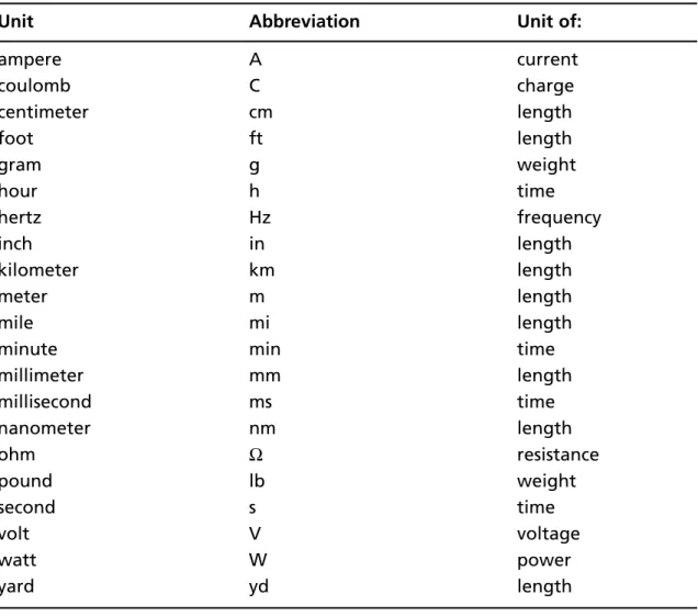
Units
All physical quantities (except ratios) are measured in terms of basic amounts called units.
The units for various physical quantities, along with the abbreviations commonly used, are
presented in Table 1.2.
Table 1.2 Abbreviations for Units
Unit Abbreviation Unit of:
ampere A current
coulomb C charge
centimeter cm length
foot ft length
gram g weight
hour h time
hertz Hz frequency
inch in length
kilometer km length
meter m length
mile mi length
minute min time
millimeter mm length
millisecond ms time
nanometer nm length
ohm resistance
pound lb weight
second s time
volt V voltage
watt W power
yard yd length
system (IS) of units. Some conversions between these two systems relevant to the material
in this book are presented in Table 1.3.
Table 1.3 Length in Two Different Units
U.S. Customary System Units International System Units
1 in 2.54 cm
1 ft = 12 in 30.48 cm
1 yd = 3 ft 0.91 m
1 mi 1.61 km
Equipped with these basic physics and math concepts, you are now ready to explore the
RFID fi eld. Let’s start by taking the bird’s-eye view of the RFID landscape.
An Overview of RFID: How It Works
The story of RFID starts with one word: identifi cation. RFID is here to replace existing
identifi cation technologies such as the barcode, which is used to identify an item by assigning
it a unique number. An example of the barcode is shown in Figure 1.3. No doubt you have
seen such barcodes on various products ranging from water bottles to wine cartons and from
books to cases that contain quantities of items.
Figure 1.3
An Example of a Barcode on a BookAccording to a display in the Smithsonian Institution’s National Museum of American
History, the fi rst purchase of a product with a barcode was made on June 26, 1974, at a
supermarket in Ohio. Today, almost everything that you buy from retailers has a barcode
printed on it. These barcodes help manufacturers and retailers in the following ways:
■
Keep track of inventory
■
Provide information about the quantity of products being sold
The barcode technology has the following limitations:
■
A
barcode
identifi es a type of product, not an individual item in that type.
■
Tracking is not automatic. For example, to keep track of inventory, you must scan
each barcode on every item of a product.
■
A barcode does not contain much information other than the product type
code.
■
A barcode is a read-only technology; that is, you cannot change the information on
the barcode or add new information to it.
So, the basic promise of barcodes is to provide identifi cation of products at the class level.
RFID is replacing those barcodes with a greater promise: automatic and global identifi cation
and tracking of objects (at the individual level), which could include almost anything:
individual product items in retail stores, animals, trees—even people. Here is one of many
possible scenarios relating how RFID works:
1. A label-like electronic device called a tag is attached to an object that needs to be
identifi ed and tracked. The tag contains the unique identifi cation of the object and
possibly more information about it.
2. Another electronic device called a reader is mounted at specifi c localities.
3. When a tagged object passes near any reader, the reader communicates with the tag
and gets the information that the tag has about the object.
4. The reader passes the information to a host computer, which is typically part of a
network connected to the Internet.
5. The host computers from several localities send the information about tagged
objects to a central location.
6. The information is integrated at the central location into database management
systems and can be analyzed by enterprise applications.
This scenario is depicted in Figure 1.4. The readers and tags use EM waves in the radio
wave frequency range to communicate with each other.
N
OTEThe advantages of RFID technology over barcode technology are as follows:
■
The
identifi cation and tracking offered by RFID is at individual item level as
opposed to the type level.
■
A tag can contain more information about the object than just its ID.
■
Depending on the type of tag, you can change the information on it.
■
The objects can be tracked globally, automatically, and in real time, if needed.
In other words, an RFID tag attached to an object is an intelligent barcode that can
communicate through readers to a global network system to inform it where the object is.
RFID technology can support a wide spectrum of applications, from tracking cattle to
tracking trillions of consumer products worldwide, thereby enabling manufacturers to know
the location of each product during its life cycle, from the time it’s manufactured to the time
it’s consumed and tossed in a recycle bin or a trash can. You can see that RFID is going to
be more ubiquitous than barcode, and its applications are limited only by your imagination.
Here is a list of some applications to get you started:
■
Asset tracking
This includes tracking of assets everywhere, such as in offi ces,
labs, warehouses, and libraries.
Internet
Host Computer
Reader
Antenna
Tagged Items Host Computer
Tagged Items
Reader
Antenna
Database Management System
Data
Locality 1 Locality 2
Enterprise Wide Integrated Data Applications
■
Automated toll collection system
A reader on the highway toll booth and a tag
attached to the vehicle’s windshield facilitate automatic charging to the car owner’s
account and eliminate the need for the driver to stop and manually pay the toll.
■
Health care applications
This includes positively identifying and tracking
patients in a health care facility or a hospital, linking a patient with the right
medicine and doctor or nurse, identifying unresponsive patients, and so on.
■
Livestock tracking
This includes tracking animals in places such as farms and
zoos and linking them to their proper locations.
■
Supply chain tracking
This includes tracking items through the supply chain
and managing inventory. The supply chain fi eld is the key early adopter of RFID
technology.
■
Tracking in manufacturing
This includes tracking parts during the manufacturing
process as well as tracking the assembled items.
■
Tracking in retail stores
This includes tracking store trolleys and shelves,
thereby facilitating automatic payment, checkouts, and inventory management.
■
Tracking in Warehouses
This includes real-time inventory tracking and
management in a warehouse or storeroom by tracking items inside, items coming
in, and items going out.
■
Tracking you
Yes, RFID will track any object, including people—for example,
tracking people entering a certain area for security purposes, automatic contact
management at events instead of sticking notes on bulletin boards, tracking babies
in hospitals, tracking children at theme parks and festivals, and so on.
“Hold on—tracking me?” you say, and you’d be right about the privacy issues. But that’s
a topic for another book.
So the two main players in a core RFID system are the reader and the tag. You can start
asking questions about them, such as this one: From how far apart can a reader and a tag
communicate with each other? In other words, how large is the read range? Well, it could be
anywhere from a centimeter to a few meters, depending on several factors, including the tag
type and the value of the radio frequency being used for communication, called operating
frequency.
earlier in this chapter. This is what goes on between a reader and an inductive passive tag: The
magnetic energy is transferred from the reader to the passive tag through inductive coupling
to power it up. It’s as though the reader were saying, “Hello, Mr. Tag, time to wake up and tell
me everything you know about this object.”
Just like the read range, the readers and tags come in various sizes and shapes. Figure 1.5
shows a reader and a tag on the smaller end of the size spectrum. I know your next question:
How do a reader and a tag really communicate with each other? That question goes to the
physics behind RFID, which is discussed in the next chapter.
Figure 1.5
A Reader and a Tag: Skyetek’s M1-mini (Image courtesyof Skyetek)For now, note that neither the physics behind RFID nor the RFID technology itself is
new. But it’s only recently that greatness has been bestowed upon RFID by giant infl uencers
such as the U.S. Department of Defense and Wal-Mart in their mandates and in a fl urry of
industrial mandates that followed. Now, armed with these mandates, government legislations,
and the resulting hyperbole, RFID has set its journey to change the world. The forthcoming
chapters will help prepare you to make your contribution to this revolution.
N
OTEThe three most important takeaways from this chapter are the following:
■
Electromagnetic force, one of the four basic forces that govern our universe, exhibits
itself in the form of electromagnetic waves, which underline the physics behind
RFID.
■
While working with RFID, you will use simple mathematical concepts such as
power of 10, logarithms, and some simple unit conversions.
Summary
Our universe is governed by four natural forces: gravitation force, strong nuclear force, weak
nuclear force, and electromagnetic force. Where there is a force, there is energy, which is the
ability of the force to do work. The amount of work done can be expressed in terms of
power, which is the amount of energy transfer per unit of time. Work is performed when a
force acts on an object and causes a change. For example, the Sun makes the Earth revolve
around it by exerting gravitational force on it. Similarly, charged objects separated from each
other can exert electromagnetic force on each other. How does an object exert force on
another object without touching it? That happens through the fi eld that exists between the
two objects due to the force.
Of the four basic forces in the universe, the force that is relevant to RFID is the
electromagnetic force, which exhibits itself in terms of electromagnetic waves.
Electro-magnetic waves, like any other wave, are characterized by their frequency and wavelength.
These waves cover a wide spectrum of frequencies, called electromagnetic spectrum. Waves
corresponding to one of the ranges in this spectrum are called radio waves. The radio
waves are used by an RFID system for communication.
At the heart of an RFID system are two kinds of communication devices: tags and
readers. A tag (an alternative to the barcode) is placed on an object that needs to be identifi ed
and tracked. The readers mounted at various locations read the information about the object
from the tag and report it to the host computer, which in turn can send this information to
a central location over the Internet. This way, an object can be tracked globally and in real
time in an automatic fashion.
23
Chapter 2
The Physics of RFID
Solutions in this chapter:
■
Understanding Radio Frequency
Communication
■
RFID Communication Techniques
■
Understanding Performance Characteristics
of an RFID System
■
Performing Antenna Power Calculations
■
The Travel Adventures of RF Waves
˛
Summary
Introduction
The core functionality of an RFID system is the communication between a reader and a tag.
The communication is carried out using RF waves, which are basically the EM waves with
frequencies from the subspectrum of EM frequency spectrum called
radio frequencies
. The
propagation of these waves is governed by the underlying physics principles. The goal of this
chapter is to help you understand some physics concepts related to this communication. To
accomplish this goal, we will explore three avenues: generation and propagation of the RF
wave carrying the data signal from the source to the antenna, emission of the RF wave by
the antenna into the free space, and propagation of the RF wave traveling through the space.
Pay attention to the characteristics that affect the performance of an RFID system during
this journey of the RF wave.
Understanding Radio Frequency
Communication
Generally speaking, RFID is a means to identify an object using radio frequency
transmission, which suggests that communication is involved in the identifi cation process.
The communication takes place between two devices: a reader that needs the information
and a tag that has the information. Before we dive into the physics of communication, let’s
get on the same page about some concepts that are at the heart of this communication.
Elements of Radio Frequency Communication
Radio frequency communication uses the EM waves with frequencies from a specifi c part of
the EM frequency spectrum. Therefore, the underlying physics behind RF communication is
the same as for any communication that uses electromagnetic waves to carry information.
The four major players that make this communication happen are the following:
■
Data signal This is the wave that actually contains the information that needs to
be sent to the receiver.
■
Carrier signal This is the wave that carries the data signal.
■
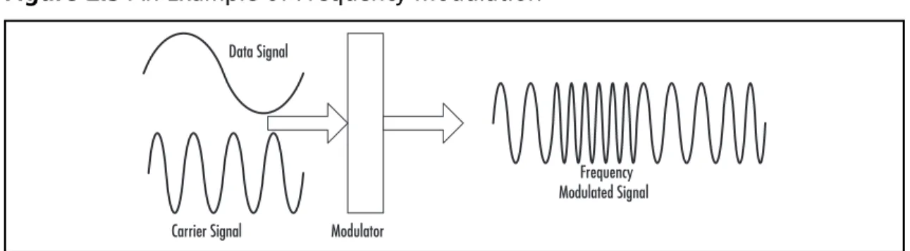
Modulation This is the process that encodes the data signal into the carrier
signal and creates the radio wave that is actually transmitted by the antenna to
propagate.
Here is how these four players work together to make the communication happen.
First, understand that the information is communicated through changes (such as vibrations)
in the carrier signal. The carrier signal itself is a constant signal unchanging in frequency
and voltage—for example, a sine wave. It represents no information. As an analogy, I would
not convey much information if I merely produced a constant sound out of my mouth,
such as:
OOOOOOOOOOOOOOOOOOOOOOO
To convey some information, I would need to speak different sentences and different
words in a sentence. In radio frequency communication, the information is encoded into the
carrier signal using a technique called
modulation
, which means variation or change. You take
the data signal that represent the information and impress it on a constant radio wave called
a carrier. The data signal, as a result, varies (or modulates) the carrier wave. Once transmitted
through an antenna, the two go together dancing over the air in the form of a modulated
signal. The process of encoding the data signal into the carrier wave is called
modulation
. The
transmitted modulated signal is received by the antenna on the receiving end and is
demodulated to obtain the data signal. The process is depicted in Figure 2.1.
N
OTEIn an RFID system, both the reader and the tag have their own antennas through which they communicate with each other. A tag is also called a
transponder because it responds to the reader’s attempt to read it, and the reader is also called a transceiver because it receives information from the tag.
Figure 2.1
The Process of Communication Using ModulationModulation Circuitry
Demodulation Circuitry
Carrier Signal Data Signal
That all sounds good. But note that the original data signal itself has information in it,
which is represented by the changes inherent in the signal. So the question is: Why don’t we
transmit the original data signal, or why do we need modulation in the fi rst place?
Modulation: Don’t Leave Antenna Without It
There are several reasons for the use of modulation in communication. Discussing the
following two will be suffi cient for the scope of this book.
The Propagation Problem
A data signal generally comprises a whole range of different frequencies together. The
problem with the low-frequency components of the signal is that few communication media
will allow the propagation of low frequencies without distortion. Modulation presents the
solution to this problem by copying these low-frequency components to high-frequency
carrier waves.
The Transmission Problem
The low-frequency data signal will have a high wavelength and as a result will require very
large antennas for transmission and reception. Here is the rule of thumb: To achieve a useful
amount of radiation, the antenna length should be at least one quarter of the wavelength of
the wave to be propagated. For example, consider a signal component with frequency of
1 KHz. The wavelength for this wave will be:
= c /f = (3 × 10⁸ m/s)/(103 1/s) = 300 km
Antenna length = /4 = 75 km
A 75-kilometer-high antenna (the tower of Babylon)? You get the point. Modulation
solves this problem by sending the low-frequency signal inside a high-frequency carrier wave.
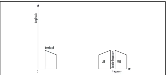
Frequency Bands in Modulation
In the description of the modulation used for communication, some terms referring to
different frequency bands are often used. A
frequency band
refers to a specifi c range of
frequencies. These terms are described as follows:
■
Baseband This is the range of frequencies of the original data signal before
modulation.
■
Sideband This is the frequency band on either the higher side or the lower side of
the carrier frequency band within which the frequencies produced by modulation fall.
■