SUPERVISOR APPROVER
"I I We admit that to have read this report and it has follow the scope and quality in Partial Fulfillment Of Requirements For The Degree Of
Bachelor of Electronic Engineering (Industrial Electronic)"
Signature
Supervisor Name Mr. Sani Irwan Bin Md Salim
REAL TIME CLOCK DISPLAY (PART 1)
HAHEI KUAI
This Report is submitted in Partial Fulfillment of Requirements for the Bachelor
Degree of Electronic Engineering (Industrial Electronic)
Faculty of Electronic Engineering & Computer Engineering Kolej Universiti Teknikal Kebangsaan Malaysia
18 March 2005
Ill
ACKNOWLEDGMENT
I treat as valid this report is doing by myself except summary and quotation in every part that I had clear source.
I would like to express our greatest gratitude and sincere thanks to my supervisor, Mr. Sani lrwan Bin Md. Salim, for his valuable advice and assistance in the supervision and consultation of this Final Year Project. In fact, he gave me guidance when obstacles arise throughout this period of time. Once again, I thank him for his tolerance and endeavors.
Thanks to Miss Toh Yen Yin, Mr. Hafizul, Mr. Lo Jin Kui and Miss Tan Lee Chin who had help me a lot of my project in progress.
Signature
Writer Name Ha Hei Kuai
IV
DECLARATION
This Final Year Project contains information pertaining of Real Time Clock
Display using LED Dot Matrix. This project comes under the subject BEKU4983 Project offered by Faculty of Electronic Engineering & Computer Engineering,
KUTKM. This documentation report aims to provide the reader about the overall
information techniques about this project. The focus of the project is on accuracy the real time clock display in LED dot matrix.
I admired that this is an
.
original my own work with the exception which Ihave referenced them to explained sources.
v
ABSTRACT
Predominantly, the title of this project is Real Time Clock Display (Part I)
for design circuit and troubleshooting. The project is about the design of a Real Time
Clock I Timer circuit using microcontroller that would accept inputs from switches,
set and display the current time, set multiple timers to activate a particular device
connected to the circuit. This Application Note explains how to control the display of
characters on a 5x7 LED matrix display using the microcontroller PIC16F877 MCU.
A ten-unit 5x7 matrix display (350 LEDs) is controlled by microcontroller
PIC16F877 (40 pins).
The clock operates in either the 24-hour or 12-hour format with AM/PM
indicator. The RTC provided in this Application Note facilitate easy implementation
for displaying clock on a 5x7 LED matrix. It has a display which is 50 columns wide,
enabling 10 characters to be shown at any one time.
The characters in each message are stored in an EEPROM with one byte
corresponding to one column of dots. Storing the characters in this way rather than as
their ASCII codes has the advantage that, apart from being simpler to decode with
the electronics, any character or graphic needed can be easily formed. The circuit
runs from a 5V DC regulated supply and consumes around 300mA peak when at
Vl
ABSTRAK
Secara keseluruhannya, tajuk projek ini ialah Paparan Jam Dengan Masa
Yang Tepat (Bahagian I) untuk rekabentuk litar dan penyelesaian masalah. Projek ini
adalah berkenaan dengan rekabentuk jam dengan masa yang tepat / litar pengawasan
masa menggunakan mikro-pengawal yang boleh menerima input-input dar;pada
pembuka, set dan menunjukkan masa yang terkini, merangka pelbagai penetapan
masa untuk mengaktifkan pelan tertentu yang disambung kepada litar. Nota aplikasi
ini menerangkan cara untuk mengawal paparan aksara atas matriks LED 5x7 yang
ditunjukkan dengan mikro-p~ngawalan PIC16F877 MCU. Sepuluh unit paparan matriks 5x7 (350 LEDs) dikawal oleh mikro-pengawal PIC16F877 (40 pin).
Format jam ini beroperasi sama ada secara 24-jam atau 12-jam dengan
penunjuk AM/PM. RTC yang dibekalkan dalam nota aplikasi ini memudahkan
pelaksanaan untuk memaparkan jam atas matriks 5x7 LED. Ia mempunyai paparan
seluas 50 ruang , ini supaya membenarkan 10 aksara untuk dipaparkan pada suaru
masa.
Aksara dalam setiap mesej yang disimpan dalam satu EEPROM dengan satu
bit bertindak ke satu ruang titik. Penyimpanan aksara dengan cara ini kalau
dibandingkan dengan kod-kod ASCII mempunyai kelebihannya, selain daripada
mudah untuk dekod dengan elektronik, sebarang aksara atau grafik yang diperlukan
boleh dibentuk dengan mudah. Litar ini berfungsi daripada SV DC yang ditawarkan
dan menggunakan lebih kurang 300mA untuk mencapai puncaknya apabila LED
memanca.l. Jam paparan mi menjadi lebih tepat dengan meggunakan jam masa yang
sebenamya, RTC dan dikawal oleh PIC16F877.
TABLE OF CONTENT
CHAPTER DESCRIPTION PAGE
PROJECT TITLE ... .
SUPERVISOR APPROVER ... ii
ACKN'OWLEDGl\ilENT ... iii
DECLARATION ... iv
ABSTRACT ... v
ABSTRAK ... vi
TABLE OF CONTENT ... vii
LIST OFT ABLE ... x
LIST OF FIGU'RE ... xi
LIST OF ABBREVIATION·... xii
LIST OF APPENDIX ... xiv
1 INTRODUCTION ... 1
1.1 OBJECTIVES ... ... ... ... ... ... ... 2
1.2 PROJECT SPECIFICATION ... ... ... .. 3
1.3 REPORT ORGANIZATION ... 3
2 LITERATURE REVIEW ... 5
2.1 PREVIOUS STUDIES & RESEARCH ... 5
2.2 RECENT RELEVANT PROJECT... 6
2.2.1 PCF8583 Real Time Clock........................ 6
2.2.2 ECPE-5 PIC Project Board...................................... 7
2.2.3 ZX81 Real Time Clock Project................................. 9
2.2.4 PIC Project-Turn ON A LED...................... 10
3 PROJECT l\llETHODOLOGY ... 14
3 .1 PROCEDURES . ... ... ... ... ... ... 14
3.2 METHODS ... 15
3 .3 THE PROCESS FLOW CHART ... 15
3.4 THE BLOCK DIAGRAM OF PROJECT... 17 3 -1 1 Operation of the Block Diagram of Project . ... .... ... .. . . .. 17 3.5 5X7 LED UOT MATRIX DISPLAY WIRING SPECIFICATION ... ... ... 19
4 COMPONENT DESCRIPTION ... 20
4.1 MICROCONTROLLER ... 20
4.2 WHY USE A MlCROCONTROLLER? ... 21
4.3 DEVELOPMENT SYSTEM .. ... 21
4.3.1 PIC16F877 Programmer Hardware Features... 22
4.3.2 PIC16F877 Programmer Software Features... 22
4.3.3 Data and Pin Diagram of PJC16F877 ... 23
4.3.4 Memory Organization............. 24
4.3.5 Program Memory Organization ............ 24
4.4 REAL TIME CHIP, RTC ... 25
4.4.1 Component Characteristics....... 26
4.4.2 Pin Assignment... 27
4.4.3 SDA - Serial Data.......... 27
4.4.4 SCL - Serial Clock... 27
4.4.5 Operation .............................. 28
4.4.6 Data Transfer.................................... 29
4.4. 7 Control Register................... 30
4.4.8 The RTC and RAM Registers................... 30
4.5 THE EEPROM ... ... 31 4. 5.1 Serial Data (SDA) .. .. .. .. .. .. .. . .. .. .. .. .. .. . .. . .. .. . .. .. .. .. .. .. .. .. .. .. .. .. .. . 3 2 4.5.2 Serial Clock (SCL) ... 32
4.5.3 Function Description.................. 32
4.5.4 EEPROM Libr.ary ... 33
4.5.5 Flash Memory Library.................. 33
5 CIRCUIT DESCRIPTION ... 35
5.1 RTC DISPLAY CIRCUIT DESCRIPTION ... 35
5.1.1 RTC, EEPROM, Crystal, and Switch Circuit... 35
5.1.2 I2C Library... 37
5. 1.3 Display Clock In 5x7 LED Dot Matrix... 38
5. 1 .4 Counter Circuit .. .. .. .. .. .. . .. .. .. .. . .. .. .. .... .. .. .. .. .. .. .. .. .. .. .. . .. .. .. .. .. .. 3 9 5.1.5 Ti.ming Diagram of Counter............. 43 5.2 TIME & DATE MODE... 44
5.3 TIME CLOCK SETTING... 44
6 OUTPUT RESULT ...... 45
6.1 SYNCHRONIZED CLOCK .... ... ... ... 45
6.2 INITIALIZATIONS ... .... ... ... 46
6.3 TRANSISTOR DRIVERS .. ... 46 6.4 THE LED 5x7 DOT MATRIX DISPLAY... 47
6.4.1 LEDResistors ... 47
6.4.2 LED Matrix Construction........ 48
6.4.3 Interfacing the LED Matrix to MCU Hardware ... ... ... .. 49
6.5 OUTPUT OF SCANNING... 51
©
Universiti Teknikal Malaysia Melaka7 DISCUSSION & CONCLUSION ... 52
7.1 PROBLEM ANALYSIS /TROUBLESHOOTING... 52
7.2 REAL-TIME VS VIRTUAL TIME... 53
7.3 FUTURE IMPROVEMENT... 54
7.4 CONCLUSION ... 55
REFERENCES... 57
APPENDIX... 58
x
LIST OF TABLE
NO TITLE PAGE
4.1 Data Of Microcontroller PIC l 6F877 ... 23
6.1 Data in Dot Matrix .. .... ... ... ... .. ... .... ... ... ... ... ... ... .. .. .. . . 51 7 .1 Real-Time VS Virtual Time . . ... ... ... ... 53
XI
LIST OF FIGURE
NO TITLE PAGE
2.1 Display Output Of The PCF8583 Real Time Clock ... 7
2.2 LED Display Circuit ... ... ... ... ... 12
3 .1 The Process Flow Chart . . . .. . .. . ... ... . ... ... . .. .. . .. . . .. . .... . ... .. .. . .. ... . . .. .. . . . 16
3.2 The Block Diagram Of Project... 17 3.3 ELM-2004EWA5x7 LED Dot Matrix Display... 19
3.4 ELM-2004EWA 5x7 LED Dot Matrix Display Wiring Specification ... ... ... ... ... ... .... ... ... 19
4.1 40 Pin PDIP ... 23
4.2 PIC16F877A Program Memory Map and Stack... 25
4.3 Real-Time Clock Pin·Assignment ... 27
4.4 Block Diagram of Real-Time Clock... 28
4.5 The RTC and RAM registers ... ... ... 31
5.1 RTC, EEPROM, Crystal And Switch Circuit ... 35
5.2 Interface 24LC256 to PIC ... 37
5.3 Display Clock In 5x7 LED Dot Matrix ... 38 5.4 Counter Circuit ... 39 5.5 Counter ... 39
5.6 One Dot Matrix Circuit by Using Proteus ... 40 5.7 Counter 4017 ... 42
5.8 Timing Diagram Of Counter ... 43
6.1 Display In Dot Matrix ... 45
6.2 Transistor Driver... 46
PCB LED MCU PIC EEPROM RTC IC PICC BCD DAC ADC UART CPU ROM I/O SPI RISC Hz MHz DC RAM
pv,, 1\11
SSP
12C
LIST OF ABBREVIATION
- Printed Circuit Board
- Light Emitting Diode
- Microcontroller Unit
Peripheral Interface Controller
Programmable Integrated Circuit
XII
- Electrically Erasable Programmable Read Only Memory
- Real Time Clock
- Int~grated Circuit
- Peripheral Interface Controller Card
- Binary-Coded Decimal
- Digital To Analog Converter
- Analog To Digital Converter
- Universal Asynchronous Receiver-Transmitter
- Central Processing Unit
- Read-Only Memory
- Input I Output
- Serial Peripheral Interface
- Reduced Instruction Set Code
- Hertz
- MegaHertz
- Direct Current
- Random-Access Memory
- Pulse Width Modulation
- Synchronous Serial Port
- Inter-Integrated Circuit
USART SCI PSP RD WR
cs
BOR SRAM HC CMOS PLLTTL
VDC DIPWWVB
ASCII SCL SDA GPIO LCD IEEEUniversal Synchronous I Asynchronous
Receiver I Transmitter
- Serial Communications Interface
- Parallel Slave Port
- Read
- Write
- Case Series
- Brown-out Reset
- Static Random Access Memory
- High Capacity
Complementary Metal-Oxide Semiconductor (transistor type)
- Phase-Locked Loop
- Transistor-Transistor Logic
- Volts Direct Current
- Du!il lnline Package
NIST longwave (60 Kilohertz) Standard Time Signal (Radio station callsign)
- American Standard Code for Information Interchange
- Serial Clock
- Serial Data
- General Purpose Input/Output
- Liquid Crystal Display (display technology)
- Institute of Electrical & Electronics Engineers
XiV
LIST OF APPENDIX
N
O
TITLE PAGEA CIRCUIT DIAGRAM... 58
B PRODUCT ... ... ... ... ... ... 60
C DATASHEET PIC16F877 ... 62
D DATASHEET RTC1307 ... 75
CHAPTER 1
INTRODUCTION
This project is a real .time clock display on ten 5x7 LED dot matrix. It has
the PIC16F877 MCU interfacing with the Dallas DS1307, a time keeping chip. This project only designs circuit and troubleshooting. The character is generated with a PIC chip EEPROM. This project has adapting RTC chip into PIC circuit to generate
the input for display. This real time clock is build using PIC16F877 MCU for control
and display and RTC for clock. The output device is shown in LED dot matrix
display that can be used efficiently to accommodate the functionality of PIC.
The DS 1307 chip stores the current date and time in registers of seconds,
minutes, and hours, days, months and years. The interface allows the l 6F877 to read the time keeping registers, as well as writing to any of them for changing the time. The time will be displayed on a dot matrix displays.
2
In real time clock, the accuracy of the clock is dependent upon the accuracy
of the crystal and the accuracy of the match between the capacitive load of the
oscillator circuit and the capacitive load for which the crystal was trimmed.
In hardware project its need for real time clock or delay source. Such devices
as clocks, timers, etc. are impossible to produce without knowledge of exact time.
The goal of this project is to create interrupt driven real time clock for Microchip
PIC 16F877 microcontroller to be used in various applications.
1.1 OBJECTIVES
1) To design circuit for Real Time Clock Display.
2) To troubleshoot the hardware part.
3) To apply the programmable to IC PIC.
4) To learn the functional and application of LED dot matrix display.
5) To learn the functional and characteristic of PIC16F877 and apply to
circuit RTC.
3
1.2 PROJECT SPECIFICATION
The Installation Assistant will consist of several parts, it includes :
1) A microcontroller
2) A real-time clock
3) Dot matrix
4) Counter
5) Crystal
1.3 REPORT ORGANIZATION
This report is divided into several chapters. They are:
1) Introduction
2) Literature Review
3) Project Methodology
4) Microcontroller & Real-time Chip
5) Design And Explanation Of Circuit
6) K.eal Time~ ·->~k Display
4
The first chapter is introduction that introduce about the project title. Beside
that, the objectives of the project have been comprised.
The second chapter that is the literature review about the project title. In
literature review, it includes some research on the existing implementation of the
Real-time Clock display in LCD. Moreover, explore on different areas including the
invention of real-time clock, virtue clock, and digital clock.
The third section is about the project methodology. In this chapter, the
methods and the project flow chart has been explained in clearly.
The fourth chapter is about the component of microcontroller and real-time
chip. In this chapter, the functional of microcontroller and real-time chip have been
explained clear. Each part of these components also has been explained.
For the fifth section, the objectives of this project are comprised. By this, the
circuit is designed by using rnicrocontroller with RTC to display in dot matrix. After
this, the circuit is explanation in each part of the project.
The following chapter is about the real-time clock display. In this chapter,
the functional of the EEPROM and the LED 5x7 dot matrix display. Beside that, the
differences of the real-time and virtue time have been explained.
The last chapter is the conclusion for the whole project. From this chapter, it
includes the conclusion and also the further improvement that can be made in future.
CHAPTER2
LITERATURE REVIEW
2.1 PREVIOUS STUDIES & RESEARCH
Predictability for Real-Time Clock, many hardware and software features
rely heavily on the availability of precise timing information. The application of
these features in distributed systems therefore necessitates the synchronous operation
of all its clocks. Even if these clocks are initialized with the same time, since
physical clocks drift, due to changes in physical conditions like temperature, sooner
or later, individual clocks will indicate different times.
The discrete clock is an event-driven clock advanced, whenever the scheduler
starts serving a packet, by the time needed to serve this packet. The arrival time of
any packet is determined by the value of the discrete clock at that instant. Let the
vcuiable ,:: ienotes th;:; '.i:;crete clock. dt. i is the value of the discrete clock at instant i.
6
I
dt.i = dt.i + UCThe discrete clock is related to the real-time clock. This relation is illustrated
in the following Lemma.
The LED dot matrix display described in this paper belongs to a new
generation of dot matrix displays, as the visual light emitted from the display
contains audio messages. It has long been realized that visible light has the potential
to be modulated and used as a communication channel with high entropy.
This application makes use of free space as a communication medium, and
the receiver is required to be in LOS with the transmitter. It should be noted that the
transmitter provides easy targ~t for the line-of-sight reception by the receiver. This is
because the LEDs, being on all times, are also indicators of the locations of the
transmitter. This development can lead to many new applications in the industry.
With diverse commercial and industrial applications, the experimental results in this
paper have demonstrated that the proposed idea is totally feasible.
2.2 RECENT RELEVANT PROJECT
2.2.1 PCF8583 Real Time Clock
This project is a simple demonstration of reading date and time from
":'
MSSP module at port C. Date and time are printed at LCD. The PIC micruce;nt dlcr
l 6F877 A has driven the RTC in this project. This project displays on a 2x 1 S LCD.
Time and date are retained up to 10 years with a small 3Y lithium batterj. r.: wvr~=>
with the MPLAB compiler and limited to 2K for the PIC16F877 but this is sufficient
for this projects.
Beside that, this project can use the MPLAB IDE to write a program.
Programming of the PIC was done with IC-Prog on a PIC-prograrnmer built from
Electronique pratique. The designer used the PCB layout then to create in boa:d.
Real-time clock (RTC) counts seconds, minutes, hours, date of the month1 mor.t.1-i,
day of the week, and year. The output of PCF8583 real time clock as below
...
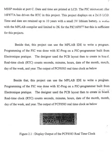
Beside that, this project can use the MPLAB IDE to write a program.
Programming of the PIC was
.
done with IC-Prog on a PIC-prograrnmer built from• J, •••• , .... Electronique pratique. The designer used the PCB layout then to create in board.
Real-time clock (RTC) counts seconds, minutes, hours, date of the month, month,
[image:21.557.52.501.33.662.2]day of the week, and year. The output of PCF8583 real time clock as below
Figure 2.1 : Display Output of the PCF8583 Real Time Clock
)
I)
switches and a potentiometer. This sub-section was designed to support a BCD ciock project envisioned. The ECPE-5 PIC Project Board is a self-contained computer that
includes a power supply, dot-matrix displays, discreet LED's, push-button switch input, digital to analog converter (DAC), digital thermometer, and a potentiometer
for analog control.
The project board is based on the Microchip I 6F877 RISC microprocessor. The processor includes on-chip VO ports, 1 Obit, ADC, timers, UART, and oscillator. The CPU section consists of the Microchip PIC l 6F877 PIC microproct::;sor, oscillator, reset circuit, and reverse voltage protection. The dot matrix display section of the project board can be configured with one large, or two small 5x7 dot matri~
LED displays.
The PIC Project Board includes some simple VO devices for testing and experimental use. These include discrete LEDs, switches, and a potentiometer. The ECPE-5 PIC Project Board includes a simple +5v power supply composed of a full wave rectifier and a fixed voltage linear regulator. The power supply components can be omitted. PICI 6F877 is a dual output digital to analog converter (DAC) with 8-bit
resolution. The interface to the DAC is a synchronous serial interface which can be
driven by the SPI interface built into the PICI6F877.
The temperature sensor is also a serial VO device. It uses a I-wire interface rather than an SPI interface. The I-Wire interface uses a single wire driven by open-collector devices as a bi-directional bus. The PIC l 6F877 has a very limited number of open-collector (or more correctly, open-drain) signals.
9
2.2.3 ZX81 Real Time Clock Project
Real Time Clock (RTC) project recently built and tested on a ZX8 l but
should be compatible with the Spectrum and other Z80 machines. Cost and
simplicity are the main reasons for choosing the DALLAS DS1287. These RTC
modules were used on some 286 AT motherboards which can often be had for free
and contain other useful parts for ZX8 l projects.
The DS1287 is functionally equivalent to the more common MC146818 but
integrates all external components including crystal and battery in a single 24 pin
DIP module. Check the date code on the unit to determine the remaining life of the
internal lithium battery, which is normally good for l 0 years or more. An internal
flag can also be used to verify a good battery.
The DS1287 is designed to work with multiplexed address/data bus MPU's
like the 6805 or the 8088. The data book shows an example of a 68000 application
but there are no Z80 application examples given. This may be the reason it is seldom
used in Z80 designs although the interface is straight forward. Rather than
multiplexing the data and address are used two separate IO addresses: one for the
address port and one for the data port.
TI·...: DS 1287 /Z?. ~ '.nterface programmer model is a block of 80 bytes, each
9
2.2.3 ZX81 Real Time Clock Project
Real Time Clock (RTC) project recently built and tested on a ZX81 but
should be compatible with the Spectrum and other Z80 machines. Cost and
simplicity are the main reasons for choosing the DALLAS DS1287. These RTC
modules were used on some 286 AT motherboards which can often be had for free
and contain other useful parts for ZX81 projects.
The DS1287 is functionally equivalent to the more common MC146818 but
integrates all external components including crystal and battery in a single 24 pin
DIP module. Check the date code on the unit to determine the remaining life of the
internal lithium battery, which is normally good for 10 years or more. An internal
flag can also be used to verify a good battery.
The DS 1287 is designed to work with multiplexed address/data bus MPU's
like the 6805 or the 8088. The data book shows an example of a 68000 application
but there are no Z80 application examples given. This may be the reason it is seldom
used in Z80 designs although the interface is straight forward. Rather than
multiplexing the data and address are used two separate IO addresses: one for the
address port and one for the data port.
Tr·c DS1287/Z~~ '.nterface programmer model is a block of 80 bytes, each
of which can be selected by writing a byte address (0 to 79 decimal) to the address
port and reading or writing data for that byte through the data port. The 74HC138
decodes IO addresses 1 F,