White Rose Research Online URL for this paper:
http://eprints.whiterose.ac.uk/9868/
Article:
Yu, M., Zha, X. and Ye, J. (2010) The influence of joints and composite floor slabs on
effective tying of steel structures in preventing progressive collapse. Journal of
Constructional Steel Research, 66 (3). 442-451 . ISSN 0143-974X
https://doi.org/10.1016/j.jcsr.2009.10.008
[email protected] https://eprints.whiterose.ac.uk/
Reuse See Attached
Takedown
If you consider content in White Rose Research Online to be in breach of UK law, please notify us by
1
The influence of joints and composite floor slabs on effective tying of steel
structures in preventing progressive collapse
Min YU1, 2, Xiaoxiong ZHA1,*, Jianqiao YE2,*
1. Shenzhen Graduate School, Harbin Institute of Technology, Shenzhen 518055, China; 2. School of Civil Engineering, the University of Leeds, Leeds, LS2 9JT, UK
Abstract: The event of the terrorist attack at 11th September 2001 in the USA has attracted increasing
attention of researchers and engineers on progressive collapse of structures. It has gradually become a
general practice for engineers to consider progressive collapse resistance in their design. In this paper, progressive collapse of steel frames with composite floor slabs is simulated by the finite element method.
The numerical results are compared with test results. The influence of the joints and the concrete slabs on the effective tying of steel beams is investigated through parametric studies. From the analysis, methods of preventing progressive collapse that can be considered in design and when retrofitting existing structures
are proposed. The results show that retrofitting a structure with pre-stressed steel cables and an increase of crack resistance in the concrete near joints can effectively improve effective tying of a structure, which
results in an enhanced structural capacity in preventing progressive collapse.
Keywords: progressive collapse; composite floor slab; joint; effective tying
1 Introduction
Progressive collapse occurs when an initial local failure spreads from element to element, eventually resulting in collapse of a disproportionately large or entire part of a structure [1]. Most of progressive
collapse events were initiated by impact and explosion that consequently caused personnel casualties [2-3]. In order to prevent progressive collapse or minimize the damages caused by progressive collapse of a
structure, extensive research has been carried out in America, the UK and Japan. Published design guidelines and codes are now available to design engineers. These include the ACI 318[4], GSA 2003[5], DOD 2005[6], BS 8100[7], Guidelines for progressive collapse control design[8] and the Eurocode[19].
The design methods adopted in the USA depend on the complexity and the importance of structures. They recognized the importance of linear and nonlinear time history analysis. In the UK, all building
designs must be checked according to risk coefficients comforting code requirement. The safety of a structure is checked by removing columns and slabs one by one, in this way to indicate that action mechanism and hanging force can prevent progressive collapse [10]. The Guidelines in Japan require more
than one load transfer path by increasing the number of redundant elements. The Eurocode aims at mainly controlling local failure caused by accident, which is a local resistance method. Provision of Progressive
collapse resistance has been adopted in the UK code for more than 30 years. In 1974, the provision of structural ties entered British Standard. Since then, a few large-scale explosions happened and the damages were confined in local scales. These events show that the effective tying behaviors produced by hanging
force have taken effect on preventing collapse [11].
In 2003, Tan and Astaneh-Asl studied effective tying of steel structures subject to failure of key
members. They also proposed a method to prevent progress collapse by using steel cables [12]. In 2005, Yu and Liew [19] studied detailed behaviour of end restrained beams in fire, including the integrity of end
2
methods to estimate load bearing mechanism and failure of beams. In 2006, Wang [20] presented a
simplified analysis to calculate effective tying of steel beams in fire. In 2008, Izzuddin etc [13-14] investigated progressive collapse of multi-storey buildings, where a three dimensional frame was analyzed
by a two-dimensional model. In the same year, Liew [21] presented a mix-element model for analyzing three-dimensional steel frame structures subject to localized damages caused by blast load and subsequently investigated their survivability under fire attack. Their study included a 3D steel frame with
solid floor slabs. The mix-element model is capable of capturing detailed behaviour of member and frame instability associated with the effects of high-strain rate and fire temperature.
In this paper, a finite element method is used to simulate progressive collapse tests of steel frames with composite floor slabs. The influences of both pin and rigid joints on effective tying developed in the steel beams are investigated. The strength of the concrete floors and their interaction with the steel beams are
also included in the numerical calculation. Finally, retrofitting a structure with steel cables to prevent progressive collapse is studied to show how the technique can improve the performance of the structure in
resisting progressive failure.
2. Experiment on progressive collapse of steel frame
2.1 Validation of the experiment
A series of tests were carried out by Tan and Astaneh-Asl [12] at UC Berkeleyl to study progressive collapse of structures made of steel-concrete composite members. One of the tests (NSF1) is used here to
validate the finite element model developed in this paper. A brief description of the test is given below and further details of it can be found in reference [12]. The specimen was a single-story steel frame with
composite concrete floor slabs. The floor was 6.1 m wide and 18.3 m long. The floor slabs were made of concrete over metal deck that was supported by longitudinal and transverse beams, as shown in Figure 1. Along frame line 2, the center column was designed as a drop column. The drop column terminated 0.915m
[image:3.595.110.479.523.702.2]above the laboratory floor. The bottom of the drop column was supported on a removable stub column. The drop column represented a column in a building that suffered severe damage by a hypothetical bomb blast.
Figure 1 Structural Framing Plan [12]
Structural steel used for the beams and columns were ASTM A36. The longitudinal and the transverse
3
with 20 gages Verco Structural Steel Decking and Type W3 Formlok. The maximum thickness of the concrete slab was 0.165m. The concrete strength was 27.6 MPa.
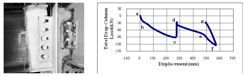
Figure 2 shows the deformation of a joint. The total load acting on the drop column is shown
in Fig.3 against the column’s displacement.
[12]. [image:4.595.102.505.129.255.2]
Figure 2 one joint after Test Figure 3 Total Drop Column Load v Displacement
2.2 Finite element modeling
It is difficult to carry out a full scale test of progressive collapse of a building, while FE analysis provides a relatively inexpensive and time efficient alternative.. If a FE model is properly validated, it is
possible to investigate dynamic behavior of a building against a wide range of parameters with the FE model. In general, for a complex problem the predictions of a FE analysis significantly depend on the
models developed by individual researchers or engineers, including specifications of material properties, failure modes and solution procedures inherited from computer software.
It has been recognized that LS-DYNA is one of the best computer software for modeling dynamic
behavior of structures. This work aims at exploring its capability of modeling progressive collapse and identifying critical parameters, constitutive and damage models that can generate comparable results with
laboratory tests.
1) Material modeling
Steel: Steel is an isotropic material which has good ductility and strength. It generates significant deformation prior to failure. In this paper, the kinematic hardening model is used in the FEM analysis.
[image:4.595.179.413.561.752.2]Fig. 4
describes the parameters used in LS-DYNA to define the stress-strain relation of steel (*MAT_PLASTIC_KINEMATIC in LS-DYNA). Table 1 presents the values of the material parameters [16].4
Table 1 Material Properties of Steel (units: MM, TON, SEC, N)
(Density)
E
(Young’s modulus) (Poisson’s ratio)
fy
(Yield stress)
Et
(Tangent modulus)
7.85E-09 210000.0 0.30 250.0 1000.0
Concrete: In order to describe the non-linear damage and the fracture characteristics of the concrete, HJC constitutive equation and the damage model are adopted. According to the test results, the axial compressive strength of the concrete is 27.6MPa. Other values of the parameters are based on Holmquist
TJ [15].
Fig. 5
shows the material parameters used in LS-DYNA to define the concrete constitutive model (*MAT_JOHNSON_ HOLMQUIST_CONCRETE in LS-DYNA). Table 2 presents the values of the parameters. The details about the HJC model can be found in reference [15].a) The constitutive relation of HJC concrete
[image:5.595.95.497.292.706.2]
b) The damage for fracture c) The relation of pressure and volumetric strain
Figure 5
description of HJC model [15]5 RO (Density) G (Shear modulus) A (Normalized cohesive strength) B (Normalized pressure hardening) C (Strain rate coefficient)
2.44E-09 14860.0 0.79 1.6 0.0070
N (Pressure hardening exponent) FC (Quasi-static uniaxial compressive strength) T (Maximum tensile hydrostatic pressure) EPS0 (Reference strain rate) EFMIN
(Amount of plastic strain before fracture)
0.61 27.6 4.0 1.0 0.010
SFMAX (Normalized maximum strength) PC (Crushing pressure) UC (Crushing volumetric strain) PL (Locking pressure) UL (Locking volumetric strain)
7.0 16.0 0.0010 800.0 0.10
D1 (Damage constant) D2 (Damage constant) K1 (Pressure constant) K2 (Pressure constant) K3 (Pressure constant)
0.0400 1.0 85000.0 -171000.0 208000.0
2) Criterion of concrete failure
The maximum primary tensile stress criterion is used to predict cracking of concrete. When the tensile stress in a concrete element is larger than the maximum primary tensile stress, the element is failed and is
removed from the model. The key words *MAT_ADD_EROSION is adopted in LS-DYNA using parameter “PFAIL” to set maximum primary tensile stress at failure. In most part of the analyses, the
tensile strength of concrete is set to 1/30 of its compressive strength, namely 1.38MPa. Parametric study is also carried out to investigate the effects of concrete tensile strength on the effective tying behavior.
3) Element types
The Hughes-Liu Beam [17] elements are employed to model all the beams and columns. The metal
deck and concrete slab are modeled by the Belytschko-Tsay shell [17] and the constant stress 8 nodes solid [17] elements, respectively. Fig. 6 shows an isometric view of the FE model.
4) Connection modeling
In the analysis, the slip between the metal deck and the concrete is ignored. To assess the effect of joints on the performance of the structure, three types of joints are considered. They are pin joints,
semi-rigid joints and hinged joints. The hinged joints are classified as joints with or without added tensile deformation. The latter is used to accommodate the notable tensile deformation of a joint due to yielding of the end plates (Figure 2). Without detailed modeling of the joint, the additional tensile deformation is
achieved by assuming a degradation of the elastic and tangent modulus of the elements in the vicinity of the joint.
5) Applied loads and Boundary conditions
In the test, the bracing under the drop column was removed first. When the structure was stabilized under the gravity, the load was applied on the column cap. In the FE analysis, in order to reduce the dynamic effect, the gravity is increased linearly and reaches its actual value in 0.5 seconds. The structure is
then kept in this stable position for another 0.5 seconds. This is followed immediately by imposing a point load at the mid-span of the front frame. The force follows the load path shown in Figure 3 up to point c.
6
Figure 6 FE model decomposition graph
2.3 Comparisons between the simulation and the experiment
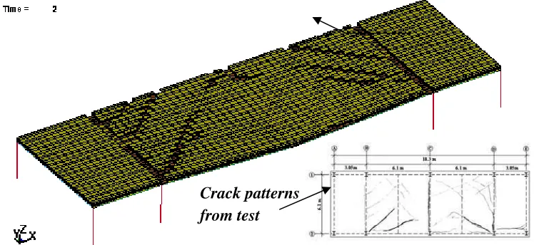
By using the above mentioned FE model and the specified parameters, the deformation of the structure and the distribution of cracks in the concrete are shown in Fig. 7. The crack pattern shown in the FE model
is taken at t=2 sec that is at the final point of the load path, i.e., at ‘c’.
Figure 7 Deformation and crack pattern of the structure
Beams and Columns
Concrete slab
Metal Deck
Exploded View
Combined model
Load position
[image:7.595.118.492.466.638.2]7
0.00 0.25 0.50 0.75 1.00 1.25 1.50 1.75 2.00 -350
-300 -250 -200 -150 -100 -50 0 50
Disp
lacement (mm)
Time (secs)
0 50 100 150 200 250
-100 -80 -60 -40 -20 0
Simulation Test
T
o
ta
l Dr
o
p
Co
lu
mn L
o
a
d
(K
N)
[image:8.595.78.521.68.209.2]Displacement (mm)
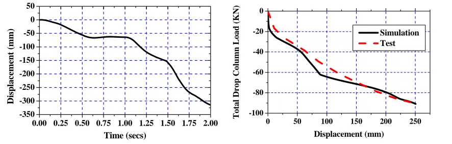
Figure 8 Displacement-time history Figure 9 Load-displacement relation
Figure 8 illustrates the time dependent displacement of the point at the location of the drop column. It is shown that the structure is stable under the gravity action at t=1s. The displacement increases then as the load exerted on the column cap increases. Figure 9 compares the load-displacement curves of the test and the FE simulation. It can be seen that the FEA results agree well with the test ones. The predictions to the crack patterns and propagation are also comparable with the observations from the test, as shown in Fig. 7. From the comparisons, it can be concluded that the FEM model can be used to simulate progressive collapse of the composite steel-concrete structure.
After the successful comparisons, the finite element model is used in the parametric studies presented in the following Sections.
3 Effect of joints on preventing progressive collapse
3.1 Effects of joints with rotational stiffness on effective tying
In structural analysis, a joint is normally classified as a rigid joint, a semi-rigid joint or a hinged joint. Under service load conditions, joints mainly bear shears. For rigid and semi-rigid connections, the joints
also need to bear moments. In a progressive collapse analysis, however, the effective tying behavior of joints needs to be included. The tying effect makes a joint bear tensile forces and produce stretching strains
as shown in Fig. 2. Thus, under such a circumstance, the force conditions at a joint are significantly different. The main aim of this analysis is to show how the joints affect the effective tying, and hence, the progressive failure path of the structure.
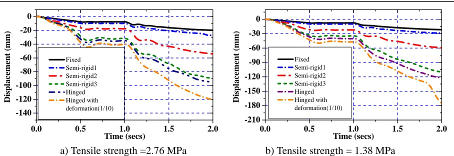
Figure 10 shows the displacements of the three types of joints: i.e., rigid joints, semi-rigid joints, and hinged joints with or without tensile deformation. The rotational stiffness k of them takes as follows: (a)
k=infinity for a rigid joint; (b) k=0 for a hinged joint and (c) k=1e+5 KN*m/rad,1e+4 KN*m/rad and 1e+3 KN*m/rad for semi-rigid 1, semi-rigid 2 and semi-rigid 3 joint.s, respectively. The additional tensile deformation was achieved by reducing the elastic and shear modulus of the beams near the joints to 1/10 of
their initial values. In Figs 10a and 10b, the displacements are shown against different concrete tensile strength. From Fig.10, the rigid connection performances the best showing the highest level of effective
tying, while the hinged joint with tensile deformation experiences significant increase of displacement in comparison with the hinged joint without the tensile deformation. This suggests that the stiffness of the joints has significant effect on the effective tying and has an important role to play in preventing
8
0.0 0.5 1.0 1.5 2.0
-140 -120 -100 -80 -60 -40 -20 0 Fixed Semi-rigid1 Semi-rigid2 Semi-rigid3 Hinged Hinged with deformation(1/10) Di sp la cemen t ( m m)
Time (secs) 0.0 0.5 1.0 1.5 2.0
-210 -180 -150 -120 -90 -60 -30 0 Fixed Semi-rigid1 Semi-rigid2 Semi-rigid3 Hinged Hinged with deformation(1/10) Di sp la cemen t ( m m) Time (secs)
[image:9.595.70.524.65.221.2]a) Tensile strength =2.76 MPa b) Tensile strength = 1.38 MPa
Figure 10 Displacement viz time for frames with different joint stiffness and concrete tensile strength
3.2 Effects of joints with tensile deformation on effective tying
When progressive collapse occurs, the force conditions at a joint are different from those of the joint when the structure is subjected to service loads. As the tensile deformation shown in Fig. 2 increases, a reduction of the effective tying and an increase of displacement are expected. Fig. 11 shows how an
increase of tensile deformation, which is achieved by a reduction of Es to E’s near the hinged joints, affects the deflection of the drop column.
0.0 0.5 1.0 1.5 2.0
-200 -150 -100 -50 0
E's/Es
1/1 1/10 1/72 1/100 Displacemen t (mm)
Time (secs) 0.0 0.5 1.0 1.5 2.0
-400 -350 -300 -250 -200 -150 -100 -50 0 50
E's/Es
1/1 1/10 1/72 1/100 Di spla cement (mm) Time (secs)
a) Failure strength =2.76 MPa b) Failure strength = 1.38 MPa
Figure 11 Displacement at the column cap for hinged joints with different tensile capacities
4 Effect of composite slabs on preventing progressive collapse
4.1 Effects of concrete tensile strength on effective tying
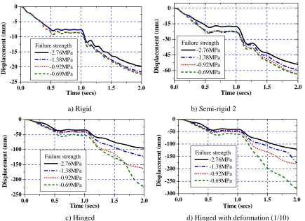
To prevent progressive collapse, composite floor slabs play a very important role in providing effective tying. This research shows that tensile strength of the composite slabs has significant effect on the
effective tying of a structure since it delays the process of cracking on the top surface of the concrete floor. This has already been shown by the two figures in Fig. 10. As shown in Figure 12, the tensile strength of the concrete has smaller effect on the deformation when the joints are rigid than when they are hinged. The
main reason for this is that the rigid joints have provided sufficient effective tying that prevents large deformation in the floors. Consequently, any increase of the tensile strength in the concrete has only
[image:9.595.79.517.374.516.2]9
prevent large deformation of the concrete floors, any increase of the tensile strength of the concrete will have notable contribute to the overall effective tying. Practically speaking, the joints, beams and concrete
slabs work together as a unit to provide effective tying in resisting progressive collapse. As the deformation progresses, the effects of the composite slabs are increasingly more significant.
0.0 0.5 1.0 1.5 2.0
-25 -20 -15 -10 -5 0 Failure strength -2.76MPa -1.38MPa -0.92MPa -0.69MPa Displacem ent ( mm)
Time (secs) 0.0 0.5 1.0 1.5 2.0
-60 -45 -30 -15 0 Failure strength -2.76MPa -1.38MPa -0.92MPa -0.69MPa Displacement (mm) Time (secs)
a) Rigid b) Semi-rigid 2
0.0 0.5 1.0 1.5 2.0
-250 -200 -150 -100 -50 0 Failure strength -2.76MPa -1.38MPa -0.92MPa -0.69MPa Displacement (mm) Time (secs)
0.0 0.5 1.0 1.5 2.0
-300 -250 -200 -150 -100 -50 0 Failure strength -2.76MPa -1.38MPa -0.92MPa -0.69MPa Displacem ent (mm ) Time (secs)
[image:10.595.81.516.146.462.2]c) Hinged d) Hinged with deformation (1/10)
Figure 12 The effect of concrete tensile strength on effective tying
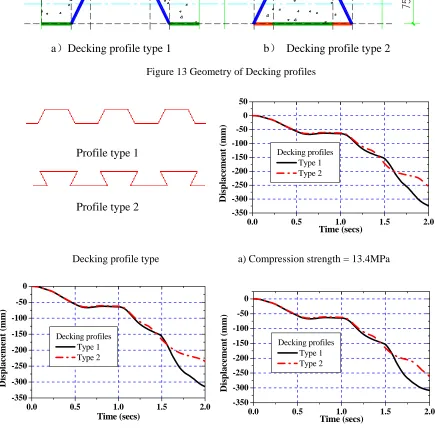
4.2 Effects of decking profiles on effective tying
In order to evaluate the influence of steel decking on the effective tying, two types of decking profile, as shown in Fig.13, are considered. In Fig.14, the time dependent displacement is also calculated against
different concrete compression strength. From the results, it can be seen that the type of decking profile has only negligible effect on the effective tying when the displacement is smaller than 0.2m. This is because
that the effective tying is provided dominantly by the joints and support beams at the early stage of collapse. It is obvious that the type two profile is more effective than the type one profile when the displacement in larger than 0.2m. This shows that towards late stage of collapse, the composite floors contribute more in
10
a
Decking profile type 1 b
Decking profile type 2
Figure 13 Geometry of Decking profiles
0.0 0.5 1.0 1.5 2.0
-350 -300 -250 -200 -150 -100 -50 0 50
Decking profiles Type 1 Type 2
Displacement (mm)
Time (secs)
Decking profile type a) Compression strength = 13.4MPa
0.0 0.5 1.0 1.5 2.0
-350 -300 -250 -200 -150 -100 -50 0
Decking profiles Type 1 Type 2
Displacement (mm)
Time (secs) 0.0 0.5 1.0 1.5 2.0
-350 -300 -250 -200 -150 -100 -50 0
Decking profiles Type 1 Type 2
Displacement (mm)
Time (secs)
b) Compression strength = 27.6MPa c) Compression strength =50.2MPa
Figure 14 The effect of different decking profiles on effective tying
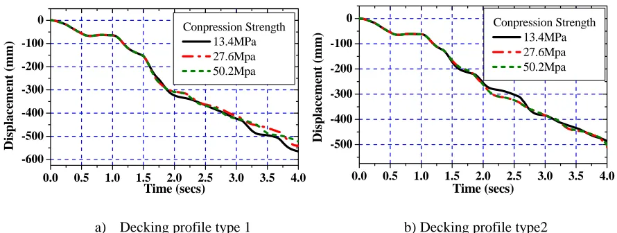
4.3 Effect of concrete compressive strength on effective tying
Compressive strength is one of the most influential parameters that govern overall performance of concrete. However, it is noticed from Fig. 14 that for each of the decking profiles, the time dependent
displacements are virtually identical for all compressive strengths considered. To investigate this further, the displacement path after T=2 second is calculated to see whether or not the compressive strength will be
more influential when the displacement is bigger. The comparisons between the slabs with different
Profile type 1
[image:11.595.77.512.183.613.2]11
compressive strength are shown in Fig. 15. It shows again that there are no substantial differences between the displacements. Close study of the numerical results reveals that the compressive stress in most part of
the concrete does not exceed its compressive strength. The failure mode shown in Fig. 7 exhibits a clear pattern of crack propagation due to the tensile stress in the concrete, which releases a significant amount of
strain energy and reduces compression in other part of the concrete as the cracks propagate.
0.0 0.5 1.0 1.5 2.0 2.5 3.0 3.5 4.0 -600
-500 -400 -300 -200 -100 0
Conpression Strength 13.4MPa 27.6Mpa 50.2Mpa
Displacement
(mm)
Time (secs)
0.0 0.5 1.0 1.5 2.0 2.5 3.0 3.5 4.0 -500
-400 -300 -200 -100
0 Conpression Strength
13.4MPa 27.6Mpa 50.2Mpa
D
isplacement (mm)
Time (secs)
[image:12.595.75.520.161.329.2]a) Decking profile type 1 b) Decking profile type2
Figure 15 The effect of compressive strength on effective tying
Figure 16 illustrates how concrete slabs affect the effective tying. Without the slabs, point g1 deflects from the original position to point g under the action of load P. While with the bending resistance of the slabs, the moments along line ‘gc’ reduces the deflection from point ‘g’ to point G. Compared with the
effect of the joints, where joint stiffness improves the effective tying capability in one-dimensional, the effect of the slabs on the structure is two-dimensional. Along line ‘gc’, the top side of the slab is in
compression and the bottom side is in tension. The effective tying can be improved if the bottom side of the concrete are reinforced or retrofitted against tension. Along the diagonals ac and ec, and in the zones outside triangle ace, tension occurs on the top surface of the slabs. Sufficient tension reinforcement is
[image:12.595.150.445.509.674.2]essential to increase progressive collapse resistance of the system.
Figure 16 The effect of slabs on effective tying
5 Measures to prevent progressive collapse
5.1 Measures in retrofitting
a
b
c
de
g P
M M
12
slabs provides effective tying that enhances the capability of a structure in preventing progressive collapse.
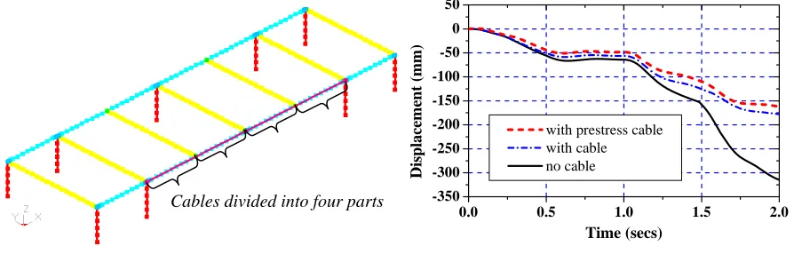
The effective tying can also be improved by improving tensile capacity of the support beams. When retrofitting an existing structure, exerting steel cables under a beam is a way to improve the tensile capacity
of the beam and hence the effective tying capability [12]. In the following analysis, a steel cable is attached to the two joints, between which the drop column is located (Fig. 17a). In the FE modeling, the element type of the steel cable is the discrete cable element. The Young’s modulus of cable is 195GPa. The cross
sectional area of the cable is 2700 mm2. The cable can be pre-stressed (LS-DYNA keywords: *MAT_CABLE_DISCRETE_BEAM). In Fig. 17 (b), for the pre-stressed cable, a force of 263.25 KN is
applied to the cable before retrofitting. The results show that with pre-stress, the deflection of the drop column is reduced significantly when the displacement is large as more tension is transferred to the cable.
0.0 0.5 1.0 1.5 2.0
-350 -300 -250 -200 -150 -100 -50 0 50
with prestress cable with cable no cable
D
isp
la
cem
en
t (m
m)
Time (secs)
[image:13.595.71.518.600.743.2]a) Cable attachment b) Displacement of the drop column
Figure 17 The effect of steel cables on effective tying
In order to study alternative ways of using cables in retrofitting, Apart from attaching the cable to the joints at the two support column as shown in Fig,17, the cables are also attached to the beams at some
intermediate locations between them. In Fig.18, the cable is attached to all the joints of the longitudinal and transverse beams between the two support columns. InFig. 19, the cable is attached to the beam at the
mid-span between the beam joints. By comparing Figs 18 and 19 with 17, it is found that by increase the number of attachment to the beam, the displacement can be reduced further. The two different attachment schemes shown in Figs 18 and 19 do not have distinctive effect on the effective tying. It is also interesting
to see that adding additional attachment has lesser impact on beams retrofitted with pre-stressed cables..
0.0 0.5 1.0 1.5 2.0
-350 -300 -250 -200 -150 -100 -50 0 50
with prestress cable with cable no cable
Disp
la
cem
en
t (mm)
Time (secs)
a) Cable attachment b) Displacement of the drop column Cables divided into two parts
13
Figure 18 The effect of steel cables on effective tying
0.0 0.5 1.0 1.5 2.0
-350 -300 -250 -200 -150 -100 -50 0 50
with prestress cable with cable no cable
Disp
la
cem
en
t (mm)
Time (secs)
a) Cable attachment b) Displacement of the drop column
Figure 19 The effect of steel cables on effective tying
5.2 Measures in designing
When designing a structure to prevent progressive collapse, using a more rigid connection is a very
effective measure. A joint that can reduce tensile deformation is also important. Reinforcing a structure properly in design is more reliable and effective than retrofitting it afterwards using, e.g., steel cables. In GSA [5], Section 4 provides guidelines for progressive collapse design of reinforced concrete buildings. For
example, effective tying can be improved by increasing tensile reinforcements of slab in the region abound a column. Fig. (20b) compares the deflections of the structure shown in Fig. (20a) with and without tensile
reinforcement in the local area around the drop column. For the reinforced slab, the local area of 3.05m×3.05m is reinforced with steel. The tension failure strength of concrete is taken as 1/5 of the compression strength (27.6×1.16= 32.016MPa) and a 16% increase in tensile strength is assumed due to the
reinforcement [18]. From the results, it is obvious that the reinforcement improves the effective tying and is more effective in comparison with using steel cables.
0.0 0.5 1.0 1.5 2.0
-350 -300 -250 -200 -150 -100 -50 0 50
reinforced not reinforced
Dis
p
la
cement (mm)
Time (secs)
[image:14.595.78.514.519.660.2]a) Locally reinforced concrete b) Displacement at the drop column
Figure 20 The effect of tensile reinforcement on effective tying
6 Concluding Remarks
14
A finite element model has been established in this paper to analyses progressive collapse of steel concrete
composite structures. The model was validated against test results and then applied to study progressive collapse of structures with respect to joint properties, interactions with floor slabs and retrofitting steel
cables. From the above analysis, there are following observations and conclusions:
1. The effective tying of joints can be improved by using a more rigid connection. Consequently, it can
improve the structural capacity to prevent progressive collapse.
2. The tensile capacity of concrete in composite slabs, especially those close to joints, contributes
significantly to the effective tying. A higher tensile strength can prevent early cracking of the concrete along the transverse support beams and in the zones close to the supports.
3. Compressive strength of concrete has much less influence on progressive failure since the dominating
failure mode is cracking. Cracking and crack propagation starting from the top surface of slabs are likely to occur before the compressive strength of concrete is reached in the compression zone
4. The numerical results show that retrofitting a steel beam with a steel cable is effective. The effective tying can be further enhanced by attaching the cable to the beam at intermediate locations. It appears that an intermediate location is not necessarily to be an existing joint.
5. A decking profile with higher moment resistance can improving effective tying and has a higher progressive failure resistance, especially when the deformation is large.
6. When progressive collapse occurs, joints are subjected to significant tension, which is different from their behavior in normal load condition. Tensile Reinforcement in the vicinity of a joint is more effective than retrofitting with steel cable and can reduce the risk of progressive failure.
In summary, the current analysis represents an initial stage of FE modeling of progressive collapse. It helps
with a qualitative understanding of this very important structural failure and identifying some critical design parameters. It should be mentioned that a more accurate approach to deal with joints and failure criterions of concrete is far more complicated; demanding more experimental and theoretical studies
urgently in the future research.
Acknowledgement
The authors are grateful for the financial support from the Royal Society under the International Joint
Research Project Program and the constructive comments from the two reviewers.
References
[1]. ASCE7-05. Minimum design for buildings and other structures. American Society of Civil Engineers.2006.
[2]. NCTC.A Chronology of Significant International Terrorism for 2004.USA: National Counterterrorism Center 2005; 83 [3]. Kong L X, Jin F N and Jiang M R. Analysis of the Way and Scale of Terroristic Raid. Blasting 2007;24(3):88-29 (in
Chinese).
15 Concrete Institute. 2002.
[5]. GSA (General Service Administration). Progressive collapse analysis and design guidelines for new federal office buildings and major modernization project. 2003.
[6]. DOD (Department of Defense). Unified facilities criteria, Design of building to resist progressive collapse.2005. [7]. Eurocode 1-Actions on structures. Part 1.7: General Actions - Accidental actions. BS EN 1991-1-7:2006. Brussels:
European Committee for Standardization.
[8]. Japanese society of steel construction council on tall building and urban habitat. Guidelines for progressive collapse control design. 2005.
[9]. Structural use of concrete: Part 1: Code of practice for design and construction. British Standard Institute. 1997. [10]. Hu Q C, Sun J C, Zhen Q. Anti-seismic, Seismic Damping Control and Progressive Collapse Control of Architectural
Structure. China Building Industry Press. 2007 (in Chinese).
[11]. Liang Y, Lu X Z, Miao Z W, Ye L P. Progressive Collapse of Structures: Introduction and Comparison of Standards. Luo Yang, 2007, 195-200 (in Chinese).
[12]. Samuel Tan, Albolhassan Astaneh-Asl. Cable-based retrofit of steel building floors to prevent progressive collapse. University of California, Berkeley. 2003.
[13]. Izzuddin B A, et al. Progressive collapse of multi-storey buildings due to sudden column loss — Part I: Simplified assessment framework. Engineering Structures, Engineering Structures 2008; 30:1308–1318.
[14]. Izzuddin B A, et al. Progressive collapse of multi-storey buildings due to sudden column loss — Part II: Simplified assessment framework. Engineering Structures, Engineering Structures 2008; 30:1424–1438.
[15]. Holmquist T J, Johnson G R and Cook W H, A computational constitutive model for concrete subjected to large strains, high strain rates, and high pressures. Proceedings of 14th International Symposium on Ballistics 1993; 591-600 [16]. LS-DYNA. Keyword User’s Manual for Version 970. Livermore Software Technology Corporation. 2003. [17]. LS-DYNA. Keyword Theoretical Manual. Livermore Software Technology Corporation. 1998.
[18]. Reiterman R. Point of view: Why Steel Reinforcement is needed in Concrete Slabs. Concrete International 1996; 75-76. [19]. Yu H X, Liew J Y R. Considering Catenary Action in Designing End-restrained Steel Beams in Fire.Advances in
Structural Engineering 2005, 8(3):309-324.
[20]. Wang Y C, Yin Y Z. A simplified analysis of catenary action in steel beams in fire and implications on fire resistant design. Steel and Composite Structures 2006; 6(5):367-386.
![Figure 1 Structural Framing Plan [12]](https://thumb-us.123doks.com/thumbv2/123dok_us/8005646.210188/3.595.110.479.523.702/figure-structural-framing-plan.webp)
![Figure 5 description of HJC model [15]](https://thumb-us.123doks.com/thumbv2/123dok_us/8005646.210188/5.595.95.497.292.706/figure-description-of-hjc-model.webp)