Application of Non-superconducting Fault Current
Limiter to Improve Transient Stability
Mehrdad Tarafdar Hagh1
, Member, IEEE, Seyed Behzad Naderi2
and Mehdi Jafari2
, Student Member, IEEE
1Mechatronic Center of Excellence, University of Tabriz, Tabriz, IRAN
2
Faculty of Electric & Electronic Engineering, University of Tabriz, Tabriz, IRAN Emails: [email protected], [email protected], [email protected]
Abstract —In this paper, enhancement of transient stability of Single Machine Infinite Bus (SMIB) system with a double circuit transmission line using a Non-superconducting Fault Current Limiter (NSFCL) is proposed. Stability analysis for such system is discussed in detail. It is shown that, the stability depends on the resistance of NSFCL in fault condition. To effective improvement of stability, the optimum value of NSFCL resistance is calculated. Simulation results by PSCAD/EMTDC software are presented to confirm the analytic analysis accuracy.
Keywords-fault current limiter; transient stability; non-superconducting coil; optimum resistor
I. INTRODUCTION
Power systems have become more expanded due to the increasing electric power demand. To increase the reliability for power supply, the electric power systems are interconnected each other to give and take the electric power [1]. Therefore, the available fault currents level may exceed the maximum short-circuit ratings of the switchgear. Traditionally, to moderate the cost of switchgear and bus replacements, the most common ways to limit high-level fault currents are: splitting the power grid and introducing higher voltage connections, using current-limiting fuses or series reactors or high-impedance transformers, and using complex strategies like sequential network tripping [2, 3].
A better idea to limit the fault currents and prevent high costs is usage of FCLs. FCLs in electric power systems are also utilized to variety of performances such as the power system transient stability enhancement, power quality improvement, reliability improvement, increasing transfer capacity of system equipment, and inrush current limitation in transformers [3]-[6].
Some studies are done on system applications of FCLs recently. For transient stability studies, they are focused on superconductor type FCLs generally, and on Resistive type SFCLs (RSFCL) specially. Because the RSFCLs can consume the accelerating power of generators in fault condition and therefore, enhance the stability of the power system [6]-[11].
To the best knowledge of authors, [10] and [11] are discussed on the optimum value of resistor of superconductor. They try to make a RSFCL that has optimal resistor value in fault condition. But there are two problems. Firstly, because of
high technology and cost of superconductors, these devices are not commercially available. Especially in third world countries, design, manufacture and operation costs providing is impossible approximately. Secondly, resistance that RSFCL shows in fault condition is not constant during the fault due to its quenching characteristics [11]. So, it is not possible to equate RSFCL’s resistance to the calculated optimal value.
The optimum value for resistor of FCL that is installed at the beginning of the parallel lines is calculated infinite at [10]. In this state, faulted line will be isolated. But we will show that the optimal value for FCL resistor should have finite value and rotor speed swings in this case will be reduced to lower values.
In this paper, a structure of NSFCL is introduced. Transient stability analysis for SMIB system with a double circuit transmission line is studied and the optimum value for resistor of NSFCL is computed. The optimal value is finite and synchronous generator will has better stability than the optimal value computed at [10]. Finally, EMTDC/PSCAD software is used to show the effectiveness of optimum resistor value for enhancement of transient stability.
II. POWER CIRCUIT TOPOLOGY OF NSFCL AND ITS
OPERATION
The three phase topology of proposed NSFCL is shown in Fig. 1. This circuit is composed of following main parts: Three sets of single phase transformers, utilized as power isolation transformer, are connected to a three phase diode rectifier bridge; A non-superconductor (copper coil) magnet that is modeled by a resistor (rd) and an inductor (Ldc); A parallel
connection of a resistor (R ) and a semiconductor switch
(IGBT) that are connected in series with the dc reactor; A dc
voltage source (Vdc) used to compensate the voltage drop that
take place in both dc reactor resistance and semiconductor devices. So, it equals to [12]:
2
dc DF IGBT d dc
V = V +V +r I (1)
Where VIGBT stands for the voltage drop across IGBT and
the forward voltage drop across rectifier diodes is defined as
DF
Figure 1. Power circuit topology of proposed NSFCL
In normal operation of power system, IGBT switch is ON. So, the resistor is bypassed. By compensating the voltage drop
on diodes, IGBT and rd, total voltage drop on FCL becomes
almost zero. Therefore, FCL does not affect normal operation of power system.
As fault occurs, dc current starts to increase. When control
circuit detects fault conditions, IGBT turns off. So, R enters to
the current path and limits the fault current. By removal of fault, IGBT turns on again and power system returns to the normal state.
It is important to note that, if the value of the resistance that NSFCL shows in fault condition at ac side of rectifier bridge,
,
FCL ac
R , be optimum from the stability point of view, it will
lead to the best improvement of power system transient
stability. On the other hand, the value of RFCL ac, is proportional
to the value of R. So, it is possible to achieve to the best
enhancement of stability by selecting a proper value for R.
Note that the value of Ldc does not affect the impedance of
NSFCL.
III. TRANSIENT STABILITY ANALYSIS USING NSFCL
Fig. 2 shows single line diagram of power system with NSFCL at the beginning of one of the parallel lines. We
assume that reactance of parallel lines (XL) are equal. At
pre-fault condition, transfer power can be expressed by:
(
)
sin 0P= EV X δ (2)
where:
E: RMS line to line synchronous generator voltage
V: RMS line to line infinite bus voltage
X: Total reactance (Xt=Xd+Xt+XL 2)
d
X : Unsaturated reactance of generator
t
X : Transformer reactance
L
X : Line reactance
0
δ : Load angle
When fault occurs at point F, without using NSFCL, because of reducing transfer power, synchronous generator will be unstable, probably (depends on fault type and mechanical
power of generator (pm)). Using NSFCL at the beginning of
the parallel lines can ensure stability of generator. Fig. 3 shows the equivalent circuit at fault state with NSFCL after applying star to delta transformation in Fig. 2.
To compute output power of generator, firstly, we calculate
output current of generator (Ig) in Fig. 3. So we have:
(
2)
(
(
0)
1)
g b a
I = E∠δ Z ∠α + E∠ − ∠δ V Z ∠α (3)
(
)
(
)
(
)
(
)
2
( 2 )
( 2 )
( 2 )
a
b
F L L
L L
L L
d t
Z b c bc a
Z a c ac b
a Z jRX R j X
b X R j X
c jX jRX R j X
X X X
= + +
= + +
= + +
= − +
= ′+ +
′ = ′+
(4)
Where ZF and Xd′are fault impedance and unsaturated
transient reactance, respectively. In the worst condition that
three phase fault occurs, ZF is equal to zero, approximately.
In fault condition, output power of generator can be expressed by:
(
)
(
)
(
)
2 2
1 2
1
( ) cos cos
sin( 2)
f g a b
a
P real I E E Z E Z
EV Z
δ α α
δ α π
∗
= ∠ = +
+ + −
[image:2.612.310.549.401.645.2](5)
Figure 2. Single line diagram of power system with NSFCL
It is clear that (5) depends on RFCL ac, and it is sum of the
consumed power of NSFCL resistance and the transfer power. To achieve the minimum rotor speed swing of synchronous
generator after fault, the optimal value of RFCL ac, must be
chosen. It is obvious that minimum rotor speed swing results in maximum critical load angle. To obtain the optimal value of
,
FCL ac
R , output power of generator in fault condition and
pre-fault condition should be equated. In this state, consumed
power of RFCL ac, be equated faulted line transfer power before
fault. In addition, because of same characteristics of parallel lines, transfer powers of each line are equal. So we have:
(
2)
(
)
, 2 sin 0
FL PCC FCL ac
P = V R = EV X δ (6)
(
2)
(
)
, 2 sin 0
FCL ac PCC
R = V X EV δ (7)
Where VPCC and PFL are point of common coupling
voltage and faulted line transfer power in fault duration,
respectively. In addition, VPCC can be expressed by:
PCC g
V =E∠δ −jX I′ (8)
where Ig is computed from (3).
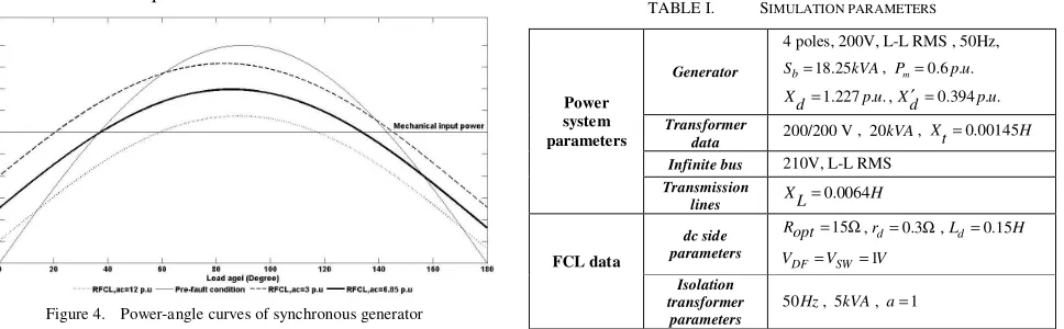
Fig. 4 shows the power-angle curves of synchronous generator. For optimal value of RFCL ac, , power-angle curve in
fault duration is passes work point of generator before fault.
It should be noticed that RFCL ac, is not equal to numerical
value of resistor at dc side of diode rectifier bridge (RFCL dc, ).
Therefore, value of RFCL dc, must be calculated according to
the optimum RFCL ac, value.
To obtain the relation between RFCL ac, and RFCL dc, , ac and
dc sides active powers (PFCL ac, and PFCL dc, , respectively)
[image:3.612.72.556.516.666.2]must be considered equal. So:
Figure 4. Power-angle curves of synchronous generator
, ,
FCL ac FCL dc
P =P (9)
2 2
, ,
6 sin( )
3 2
3
m
m
FCL ac FCL dc
V V
R R
π π
= (10)
Where, Vm is the peak of isolation transformer secondary
voltage.
As a result:
, 2 ,
18
FCL dc FCL ac
R R
π =
(11)
IV. SIMULATION RESULTS
Simulations are performed on a power system such as Fig. 2. Parameters of simulation are as Table I.
Fault occurs at 20 (sec) and lasts 0.16 (sec) (8 cycles of power system frequency).
Fig. 5 shows the phase A voltage of generator terminal without NSFCL in the system. It is observed that voltage distortions take place and system becomes unstable. But by installing the NSFCL at the beginning of faulted line, voltage of generator is restored and instability is prevented. Fig. 6 shows the phase A voltage of generator terminal with NSFCL and proves this fact.
Generator current with and without NSFCL is shown in Fig. 7 and 8. Fig. 7 shows that without using NSFCL, fault current is not limited and therefore, generator can not hold its stability. By using NSFCL, as shown in Fig. 8, the fault current is limited properly and generator became stable.
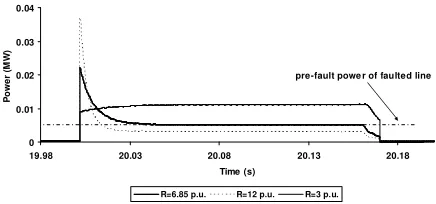
Fig. 9 shows the consumed power of NSFCL during the
fault for three values of R as follows: 3 (p.u.), 6.85 (p.u.) (the
optimum value) and 12 (p.u.). Considering Fig. 9, it is clear that the consumed power by NSFCL during the fault for
optimum value of R is closer to the pre-fault value of the
TABLE I. SIMULATION PARAMETERS
Generator
4 poles, 200V, L-L RMS , 50Hz,
18.25 b
S = kVA, Pm=0.6 . .p u
1.227 . .
Xd= p u,Xd′ =0.394 . .p u
Transformer
data 200/200 V , 20kVA, Xt=0.00145H Infinite bus 210V, L-L RMS
Power system parameters
Transmission
lines XL=0.0064H dc side
parameters
15
Ropt= Ω,rd=0.3Ω,Ld=0.15H
1
= =
DF SW
V V V
FCL data
Isolation transformer
parameters
transmitted power from the faulted line. So, it leads to decrease the accelerating area and consequently, minimize the oscillations of generator rotor speed. Fig. 10 shows the rotor
speed oscillations of generator for different values of R after
the fault. It is important to note that the best response is observed for the case that NSFCL had the optimum value of
R. In this case, rotor speed oscillation is lower than the cases
that NSFCL has other values of R.
-0.3 -0.15 0 0.15 0.3
19.9 20.1 20.3 20.5 20.7 20.9
Time (s) G e n e ra to r te rm in a l v o lt a g e ( k V
[image:4.612.321.539.55.157.2]) Fault duration
Figure 5. Phase A voltage of generator terminal without NSFCL
-0.3 -0.15 0 0.15 0.3
19.9 20.1 20.3 20.5 20.7 20.9
Time (s) G e n e ra to r te rm in a l v o lt a g e ( k V ) Fault duration
Figure 6. Phase A voltage of generator terminal with NSFCL
-0.2 0 0.2 0.4
19.9 20.1 20.3 20.5 20.7 20.9
Time (s) C u rr e n t (k A ) Fault duration
Figure 7. Generator current without NSFCL
-0.06 -0.03 0 0.03 0.06
19.9 20.1 20.3 20.5 20.7 20.9
Time (s) C u rr e n t (k A ) Fault duration
Figure 8. Generator current with NSFCL
0 0.01 0.02 0.03 0.04
19.98 20.03 20.08 20.13 20.18
Time (s)
P o w e r (M W )
R=6.85 p.u. R=12 p.u. R=3 p.u.
pre-fault powe r of faulted line
Figure 9. Consumed power of NSFCL during the fault for three values of R
1490 1495 1500 1505 1510
19.5 20.5 21.5 22.5 23.5
Time (s) R o to r s p e e d ( rp m )
without NSFCL for R=6.85 p.u. for R=12 p.u. for R=3 p.u.
Figure 10. Rotor speed oscillations of generator
V. CONCLUSION
In this paper transient stability improvement of power system with double circuit transmission line using NSFCL is presented. Proposed structure can enter an optimum value of resistor to the utility without needing to isolate faulted line. Optimum resistor leads to proper enhancement of transient stability. Analytical analyses are performed for pre-fault and fault conditions. Simulation results by EMTDC/PSCAD are involved for different values of resistor to validate the effectiveness of optimum resistor value. In general, proposed structure with low cost and available technology has good capability to improve the transient stability.
REFERENCES
[1] Y. Shirai, , K. Furushiba, Y. Shouno, M. Shiotsu, and T. Nitta,
“Improvement of Power System Stability by Use of Superconducting
Fault Current Limiter With ZnO Device and Resistor in Parallel,” IEEE
Trans. Appl. Supercond., vol. 18, no. 2, pp. 680-683, June 2008.
[2] Lin Ye, LiangZhen Lin, and Klaus-Peter Juengst, “Application Studies
of Superconducting Fault Current Limiters in Electric Power Systems,”
IEEE Trans. Appl. Supercond., vol. 12, no. 1, pp. 900-903, March 2002.
[3] Mehrdad Tarafdar Hagh, Mehdi Abapour, “Nonsuperconducting Fault
Current Limiter With Controlling the Magnitudes of Fault Currents,”
IEEE Trans. Power Elc., vol. 24, no. 3, pp. 613-619, March 2009.
[4] M. M. R. Ahmed, G. A. putrus, L. Ran, “Power Quality Improvement
Using Solid State Fault Current limiter,” IEEE, Transmission and
Distribution Conference, Asia Pacific, vol. 2, pp. 1059-1064, Oct. 2002.
[5] M. Tarafdar Hagh and M. Abapour, “DC reactor type transformer inrush
current limiter,” IET Electr. Power, vol. 1, no. 5, pp. 808–814, Appl.,
2007.
[6] M. Tsuda, Y. Wlitani, K. Tsuji, K. Kakihana, “Application of Resistor
Based Superconducting Fault Current Limiter to Enhancement of Power
System Transient Stability,” IEEE Trans. Appl. Supercond., vol. 11,
[image:4.612.73.286.147.238.2] [image:4.612.323.538.194.294.2][7] K. Furushiba, T. Yoshii, Y. Shirai, K. Fushiki, J. Baba and T. Nitta,
“Power System Characteristics of the SCFCL in Parallel With a Resistor
in Series With a ZnO Device,” IEEE Trans. Appl. Supercond., vol. 17,
no. 2, pp. 1915-1918, June 2007.
[8] H. Hooshyar, M. Savaghebi, “RSFCL Optimum Shunt Resistance
Determination to Enhance Power System Transient Stability,”
Universities Power Engineering Conference, UPEC, 43rd International, pp. 1-5, September 2008.
[9] Hiroyuki Hatta, Shinichi Muroya, Tanzo Nitta, Yasuyuki Shirai, and
Masaumi Taguchi, “Experimental Study on Limiting Operation of Superconducting Fault Current Limiter in Double Circuit Transmission
Line Model System,” IEEE Trans. Appl. Supercond., vol. 12, no. 1, pp.
812-815, March 2002.
[10] Y. Ye, L. Xiao, H. Wang, and Z. Zhang, ‘‘Research on resistor type
superconducting fault current limiter in power system,” in Proc.
IEEE/PES Transmiss. Distrib. Conf. Exhib., Asia Pacific, 2005.
[11] Byung Chul Sung,, Dong Keun Park, Jung-Wook Park, and Tae Kuk
Ko, “Study on a Series Resistive SFCL to Improve Power System
Transient Stability: Modeling, Simulation, and Experimental
Verification,” IEEE Trans. Ind. Elec., vol. 56, no. 7, pp. 2412-2419, July
2009.
[12] M. Tarafdar Hagh and M. Abapour, “Non-superconducting fault current
limiters,” Euro. Trans. Electr. Power, vol. 19, no. 5, pp. 669-682, 27