This is a repository copy of
Predicting the Effect of Vibro Stone Column Installation on
Performance of Reinforced Foundations
.
White Rose Research Online URL for this paper:
http://eprints.whiterose.ac.uk/92826/
Version: Accepted Version
Proceedings Paper:
Al Ammari, K and Clarke, BG (2016) Predicting the Effect of Vibro Stone Column
Installation on Performance of Reinforced Foundations. In: International Journal of Civil,
Environmental, Structural, Construction and Architectural Engineering. ICSMGE 2016:
18th International Conference on Soil Mechanics and Geotechnical Engineering, 01-02
Feb 2016, Rio de Janeiro, Brazil. World Academy of Science, Engineering and Technology
, pp. 111-117.
[email protected] https://eprints.whiterose.ac.uk/
Reuse
Unless indicated otherwise, fulltext items are protected by copyright with all rights reserved. The copyright exception in section 29 of the Copyright, Designs and Patents Act 1988 allows the making of a single copy solely for the purpose of non-commercial research or private study within the limits of fair dealing. The publisher or other rights-holder may allow further reproduction and re-use of this version - refer to the White Rose Research Online record for this item. Where records identify the publisher as the copyright holder, users can verify any specific terms of use on the publisher’s website.
Takedown
If you consider content in White Rose Research Online to be in breach of UK law, please notify us by
Abstract—Soil improvement using vibro stone column techniques consists of two main parts: (1) the installed load bearing columns of well-compacted, coarse-grained material and (2) the improvements to the surrounding soil due to vibro compaction. Extensive research work has been carried out over the last 20 years to understand the improvement in the composite foundation performance due to the second part mentioned above. Nevertheless, few of these studies have tried to quantify some of the key design parameters, namely the changes in the stiffness and stress state of the treated soil, or have consider these parameters in the design and calculation process. Consequently, empirical and conservative design methods are still being used by ground improvement companies with a significant variety of results in engineering practice. Two-dimensional finite element study to develop an axisymmetric model of a single stone column reinforced foundation was performed using PLAXIS 2D AE to quantify the effect of the vibro installation of this column in soft saturated clay. Settlement and bearing performance were studied as an essential part of the design and calculation of the stone column foundation. Particular attention was paid to the large deformation in the soft clay around the installed column caused by the lateral expansion. So updated mesh advanced option was taken in the analysis. In this analysis, different degrees of stone column lateral expansions were simulated and numerically analyzed, and then the changes in the stress state, stiffness, settlement performance and bearing capacity were quantified. It was found that application of radial expansion will produce a horizontal stress in the soft clay mass that gradually decrease as the distance from the stone column axis increases. The excess pore pressure due to the undrained conditions starts to dissipate immediately after finishing the column installation, allowing the horizontal stress to relax. Changes in the coefficient of the lateral earth pressure K , which is very important in representing the stress state, and the new stiffness distribution in the reinforced clay mass, were estimated. More encouraging results showed that increasing the expansion during column installation has a noticeable effect on improving the bearing capacity and reducing the settlement of reinforced ground, So, a design method should include this significant effect of the applied lateral displacement during the stone
column instillation in simulation and numerical analysis design.
Keywords— Bearing capacity, Design, Installation, Numerical
analysis, Settlement, Stone Column.
I. INTRODUCTION
any methods of stone columns installation have been developed over the last four decades to achieve well-compacted and efficient stone columns that work with
K. AL ammari is with the University of Leeds, Civil Engineering, Woodhouse Lane, LS2 9JT, Leeds, UK. Email: [email protected].
B. G. Clarcke is with the University of Leeds, Civil Engineering, Woodhouse Lane, LS2 9JT, Leeds, UK.
[image:2.612.315.567.352.483.2]the surrounding clay as one system. In reality all installation methods of stone columns involve in partial to full radial displacement to the cylindrical hole in the soft clay. So the effect of this degree of lateral expansion on the response of the surrounding clay should be taken into consideration in the design process of the reinforced ground, [19]. In this study, the adopted approach for the modelling process was chosen to simulate the dry bottom-feeding system in stone column construction, which is the most commonly, used method for vibro stone column installation. This system allows the feeding of granular material from the bottom of the borehole by supplying these materials through the nose cone of the vibrator after reaching the required depth and without the need to use a water jet, Fig. 1.
Fig. 1 Vibro displacement by dry bottom-feeding method, [16].
Two major effects can be distinguished due to the installation of stone columns: the displacement of the ground due to the creation of the stone columns and changes within the soil due to movements of the vibration probe, [11] and [18]. This variation increases the lateral stress within the clay which provides additional confinement for the stone. An equilibrium state is eventually reached, resulting in an increased stiffness of the surrounding soil and an increase in the pore water pressure. Afterwards, stone columns will accelerate the rate of consolidation of soft clays, providing a drainage path and relieving excess pore water pressures, [4], [9] [
19
]and
[23
]. Elshazly [7] carried out a numerical analysis to prove the importance of taking into consideration the changes of the stress state and stiffness of the treated clay in the reinforced foundation design. This change starts after vibro-replacement stone column installation and continues during clay consolidation. They re-studied the field loading tests carried out on a single column within an extended group in the Santa Barbara waste water treatment plant, using non-linear finite element code. They applied the axisymmetricPredicting the Effect of Vibro Stone Column
Installation on Performance of Reinforced
Foundations
K. Al ammari , B. G. Clarke
homogenization method and adopted the same soil profile and geometric idealizations used by [22]. They found that installing the vibro-replacement stone columns significantly alters the soil stress state, which can be represented by the lateral earth pressure ratio K. They calibrated this parameter utilizing the back-analysis method and found that the horizontal to vertical soil stress ratio K of the clay surrounding the stone columns increases from the original value of untreated clay to the range [1.1 to 2.5] according to the layer. This study is considered to have been the first step to quantify the change in the in situ soil after vibro stone column installation and consolidation, which leads to improvement in the design of the foundation. In the second numerical analysis, Elshazly [8] searched for the relationship between the inter-column spacing and the corresponding alteration of soil stress state of the clay around the stone columns. This relationship affects the settlement performance of this system and illustrates the importance of the in situ clay between the columns and its role in increasing the capacity and reducing the settlement after the increasing of its stiffness. So any realistic and sufficient design needs to consider the effect of the properties of the in situ soil and its stiffness response to the column installation and consolidation process.
The scope of this study is to quantify the effect of the vibro installation of stone column on the performance of the treated ground as an essential part of the design and calculation of the stone column foundation.
II.MODEL DEVELOPMENT AND SPECIFICATIONS
In the last few years there were few attempts to take into account the stone column installation effect in improving the settlement performance using numerical analysis methods. They can be summarized in two main simulations methods; the first one is increasing the coefficient of lateral earth pressure (K0) in the soil around the stone column [7] and [8].
While the second based on applying cylindrical cavity expansion to stone column in modelling using extendable dummy material (with with very low stiffness stiffness). Then convert properties to stone backfill after expansion [6] and [12].
In this study the two simulation methods were combined together by Apply cavity expansion to stone columns using Guetif [12] method to take into account the changes in the soil stress state then the enhanced zone was estimated based on soil properties. After that stiffness of this enhanced zone was increase to cover its role in improving the settlement performance after consolidation.
The studied case of a single stone column that supports a circular footing is not an applicable case in the field, but it can be utilized from its results to be a framework for a real typical field cases foundation supported by a group of stone columns that . Never the less, the soft clay soil and stone column material parameters and geometry of stone column and footing were taken to be as realistic as possible.
In order to build a realistic model for a single stone column that supports a circular foundation on soft clay soil, the modelling process should involve into a series of challenges,
including the appropriate approach for simulation, selection of parameters used in the analysis, the right choices for the constitutive model that represents the studied soil and some assumptions related to the construction process of the stone column installation.
A.Soil profile
For development and validation purposes, the selected soft clay soil used in this study was Bothkennar Carse clay. It is real clay which has been extensively characterized. Bothkennar test site is a soft clay test bed site located in Scotland, on the south side of the River Forth, near Grangemouth, United Kingdom. It was chosen and purchased by the Science and Engineering Research Council (SERC) in 1987 for purpose of study and research the construction on soft clay. the stratigraphy of the site relatively consists of uniformly soft clay deposits as a result of the post-glacial sediment of the Forth River [24]. Post to purchasing, an intensive programme of field and laboratory investigations and researches were carried out to establish a full geotechnical profile for the site, including full characterisation, Permeability and hydraulic features, yielding and mechanical properties and disturbance and destructuration prior to laboratory testing, [1],[14] and [21].
Bothkennar site sediments forming the Bothkennar clay mainly consists of a crust of about 1.5m of stiff dark brown silty clay, underlined by 12-22m of general consistent of soft silty clay layer commonly called as Carse clay, over a deep layer of Bothkennar gravel. The soil is classified as clayey silt according to BS5930 with low content of sand less than 10%, and clay of average (35-50) %. The silt particles noted to be very angular giving higher friction angle for Bothkennar clay. The soil classified to be high plasticity As a result of the significant organic content in the main clay layer (3-5) % [14].
The lateral earth coefficient has been calculated as a ratio between vertical and horizontal effective stress and has been plotted by [24]. K0 for the crust clayey layer has a high values
compared with the underneath Carse clay, where K0 become
[image:3.612.346.526.537.676.2]less than 1, then it decreases slowly with the depth.
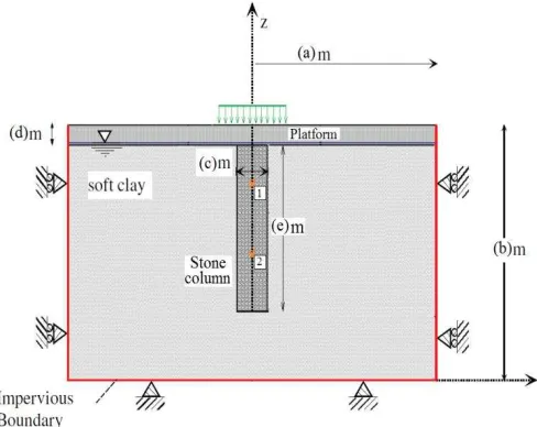
Fig. 2 Axisymmetric problem, [25].
B.Units and model type
geometry dimensions, forces, stresses and time in this model were taken as the default units in Plaxis 2D V9 (m, N, day). Consequently, all output data and curves will be showed using the same units. Simulation of the single stone column was carried out using axisymmetric analysis and without any geometric modelling, fig 2.
C.Boundary conditions
The studied model is controlled with a group of boundary conditions that can be applied differently for each calculation phase to reach an equilibrium state with the internal stresses and strains.
All boundary conditions of the model are listed below and illustrated in fig 3
1. The default general fixities were automatically applied to the boundaries of the studied model, where all nodes of the model vertical sides are fixed in X-direction (Ux =0) and free in Y- X-direction, to represent the infinite extension of the soil body mass in x-direction, while the bottom boundary which represent the deep mother soil is fully constrained in both directions (Ux = Uy = 0). The ground surface has no fixities in all direction
2. Self-soil weight was taken into account by applying the gravity effect, assuming the default gravity acceleration, g, is 9.810 m/s2, and the direction is with the negative y-axis. Default unit weight of the water is 10 kg/m3.
3. The ground water level was selected to be at the surface of the soft clay. The water is allowed to flow from the clay to the stone column drain during the consolidation, while a closed ground water flow boundary was assigned on right and bottom sides of the model considering the continuity with mother soil mass.
4. The studied soft clay was
the lower layer of
Bothkennar Carse clay
considered as normally consolidated, saturated and extends to a large depth.D.Sensitivity analysis
In order to have accurate results for the analysis using finite element technique and make these results dependent only on soil properties and geotechnical problem conditions, a group of important analysis for the features and conditions like the mesh density and the distance of the boundaries were investigated to avoid any reaction on the model results.
External boundaries are an artificial representative of real forces, extensions and conditions that define the situation of a finite element model. It is not possible to include real natural extension of a mass of soil or some events applied on it, so finite element code (Plaxis 2D AE) enable the user to substitute the reaction of these extensions and events as a restraints, displacements and forces. Consequently, user can quantify these effects and assign them to the studied model with minimum effect on the accuracy of this model. Positions of boundary restraints can significantly affect finite element
simulation results. Since the generated reaction forces and displacement in these boundaries can influence the impact of the applied forces on main interested zones. A sensitivity analysis was carried out on the studied model for both side and bottom boundaries to ensure their neutrality of any influence in analysis. It was found that there is no influence of the bottom boundary in the settlement under the footing when it is 10m or more. Therefore, it was chosen at 11m depth under the footing to have 3 m far from the base of the floating column. While the side boundary starts to affect the footing settlement results when it comes closer than 12.5m from footing centre line. So, it has been conservatively chosen at 15m distance, where the effect of the model loading is diminished.
[image:4.612.316.560.351.545.2]15-node triangular elements were selected for all the clusters in the current studied model. Mesh density sensitivity analysis was carried out and the global coarseness was taken to be medium which is sufficiently fine to achieve accurate numerical results. One preferable feature in Plaxis 2D AE is an automatic fine mesh at the interfaces and inter-element boundaries, but it is still important to check any discontinuities that may occur in these regions due to the fast changes of strains and stresses. In this model, the platform under the edge of the footing should be checked after applying the working load and refine the mesh at this area at any discontinuity case.
Fig. 3 Boundary conditions in studied model.
After finishing the sensitivity analysis, the model was simulated to be a (30 x 10) m cylindrical of solid soft clay, overlaid with 1m thickness of gravel platform. The installed vibro stone column diameter was ranged between (50-100) cm and the applied footing was 2m diameter of 50 (kPa) distributed load on both stone column and surrounded compacted clay. The model geometry is symmetric so one half of it is enough for simulation. The final model dimensions are illustrated in fig 3.
E.Models and parameters
values of were assumed for the reinforced concrete footing material in modelling; as shown in table 1, [5]. The footing thickness was assumed to be 0.5m, which is rigid enough to approximately consider some applied settlement for both stone column and surrounded soft clay. Liner elastic model was used to simulate the footing material.
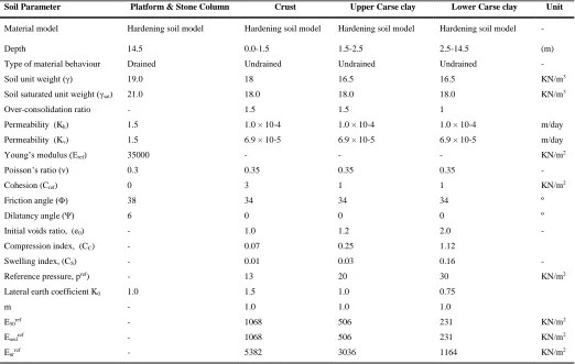
[image:5.612.43.565.184.515.2]Hardening soil model was used to represent both soft clay and stone column materials. These two choices were decided after investigating the right representative constitutive model that able to capture the changes in both of them. Adopted soil parameters for the Hardening soil model are shown in table 1.
TABLE 1
Soil parameters adopted for finite element analysis.
Soil Parameter Platform & Stone Column Crust Upper Carse clay Lower Carse clay Unit
Material model Hardening soil model Hardening soil model Hardening soil model Hardening soil model -
Depth 14.5 0.0-1.5 1.5-2.5 2.5-14.5 (m)
Type of material behaviour Drained Undrained Undrained Undrained -
Soil unit weight ( ) 19.0 18 16.5 16.5 KN/m3
Soil saturated unit weight ( sat) 21.0 18.0 18.0 18.0 KN/m3
Over-consolidation ratio - 1.5 1.5 1
Permeability (Kh) 1.5 1.0 × 10⁻⁴ 1.0 × 10⁻⁴ 1.0 × 10⁻⁴ m/day
Permeability (Kv) 1.5 6.9 × 10⁻⁵ 6.9 × 10⁻⁵ 6.9 × 10⁻⁵ m/day
Young’s modulus (Eref) 35000 - - - KN/m2
Poisson’s ratio ( ) 0.3 0.35 0.35 0.35 -
Cohesion (Cref) 0 3 1 1 KN/m2
Friction angle ( ) 38 34 34 34 º
Dilatancy angle ( ) 6 0 0 0 º
Initial voids ratio, (e0) - 1.0 1.2 2.0 -
Compression index, (CC) - 0.07 0.25 1.12
Swelling index, (CS) - 0.01 0.03 0.16 -
Reference pressure, pref) - 13 20 30 KN/m2
Lateral earth coefficient K0 1.0 1.5 1.0 0.75
m - 1.0 1.0 1.0
E50ref - 1068 506 231 KN/m2
Eoedref - 1068 506 231 KN/m2
Eurref - 5382 3036 1164 KN/m2
F.Validation
It is very important to validate the use of Plaxis 2D AE and its adopted model before studying the case of stone column installation effect. For this purpose, Plaxis 2D AE with Hardening Soil Model parameters selected for Bothkennar profile in Table 1 were used to investigate the load-displacement behavior of Bothkennar soil and then compare the results with a well-documented field load test on rigid pad footing carried out by [15]. The comparison result is shown in fig 4.
the use of Plaxis 2D AE and the choice of selected Hardening Soil Model parameters to be Adequate for the next step.
Fig 4 Comparison of Plaxis 2D AE modeling results with real load- displacement behaviour for a field footing done by [15].
III. COLUMN INSTALLATION MODELLING
[image:6.612.52.296.87.235.2]Stone column installation in this case is modelled as an undrained expansion of a cylindrical cavity. In order to perform this installation process in the finite element simulation, a procedure called (Dummy material) was adopted to avoid any discontinuity in simulating the radial expansion process. It considers the cylindrical hole made by the vibrated probe after installation and before start the radial displacement, as a fictitious purely elastic material with a very weak young modulus (First phase). This weak Dummy material can stretched when it is subjected to the radial displacement (vibro compaction of stone column material) until the radial expansion reaches the stone column radius [12]. Then the dummy material replaced by stone column material (second phase). Fig 5 illustrates the principle of installation process.
Fig. 5 Principle of stone column expansion using the dummy material.
In small deformation of the engineering structure, it is accurate enough to consider the finite element mesh in equilibrium conditions, which means that the stiffness matrix in this case is approximately constant, while in large deformation theory this stiffness matrix should be updated in each step of calculation [3]. Vibro lateral expansion of the stone column caused large displacement on the surrounded soft clay up to 45 cm in this model. So the “updated mesh”
advanced option has been considered in analysis the effect of column installation. Since stone columns are usually installed in a short period of time, the applied radial expansion to the surrounding clay was modelled as a prescribed displacement considering undrained conditions.
A.Column–soil interface
Interface elements are designed to model the interaction between the soil and structural elements surfaces (smooth and rough) including any gap or slip displacement it might happen. For the case of stone column analysis, the researchers had two different opinions; [13] and [17] considered the smear zone created between the stone column and the soft clay after installation as a low permeability thickness. This zone affects the drainage capacity of stone columns and reduces the rate of consolidation. So they use column-soil interface in their models. Many other researches like, [10], [12] and [19] believe that Due to vibro compacted installation of the stone column, the interface between the soft clay and column material is assumed to be full adhesive and the stone column becomes tightly interlocked with the surrounding soil. However, in this model no column–soil interface was considered, because of the following reasons;
1. Both of the soft clay and stone column material have a soil nature with different geotechnical properties and no possibility for any slipping or gaps after installation.
2. The focus of the current model mainly to study the changes in both the stress state and the material properties of the treated soil mass adjust to the column (including the smear zone) due to the installation and consolidation. So any prejudged assigned properties for this zone will affect the results.
3. The low permeability smear zone mentioned above has no effect on the long term performance of the stone column system.
The numerical analysis was conducted considering infinite permeability between the clay and the stone column, and allowing enough time consolidation after column installation until the minimum pore water pressure within the soil is 10% of the maximum value caused by column installation. Then Applying foundation load considering a rigid foundation (same displacement for both stone columns and clay). After that, allowing consolidation again to minimum pore water pressure within the soil is 10% of the maximum value caused by applying foundation load.
Groups of Nodes & Stress Points under the footing and at mid depth of the stone column were selected on the finite element mesh, in order to generate results for the studied model.
IV. RESULTS
Application of radial expansion will produce a horizontal stress in the soft clay mass; part of this horizontal stress is the excess pore pressure due to the undrained conditions of the saturated clay. These stresses gradually decrease as the
0 300 600 900 1200 1500
0 40 80 120 160 200 240
A
p
p
lied
p
ress
u
re
(k
P
a)
Settlement (mm)
Field Data
[image:6.612.50.286.493.610.2]distance from the stone column axis (R) increases. Immediately after finishing the column installation, the excess pore pressure starts to dissipate, allowing the horizontal stress to relax. Fig 6 and fig 7 illustrate the relationships of radial displacements, and the generated excess pore pressure before consolidation with distance from the column axis for the case of 0.2m displacement.
Fig. 6 Variation of lateral displacement within the clay with distance from the column axis (displacement degree = 0.2 m).
[image:7.612.321.559.165.339.2]Fig 6 shows that the applied lateral expansion is directly exerted by the surrounding clay, causing a displacement within the clay, which usually vanishes close to and not more than six times the value of the applied expansion.
Fig. 7 Variation of excess pore pressure within the clay with distance from the column axis (displacement degree = 0.2 m).
A.Evaluating the new stress state and the stiffness changes due to stone column installation
By taking the normalized radial stress to vertical stress, it is possible to estimate the changes in the coefficient of the lateral earth pressure K , which is very important in representing the stress state and evaluating its new distribution in the reinforced clay mass. Fig 8 shows the coefficient of the lateral earth pressure and its changes after column installation compared with its original value at rest. It is clear that the stress state rises up to about 1.6 times the initial value adjunct
to the stone column and decrease gradually with the distance to get close to its original value after about five times the column diameter (dc). Similar dramatic increase in the soil
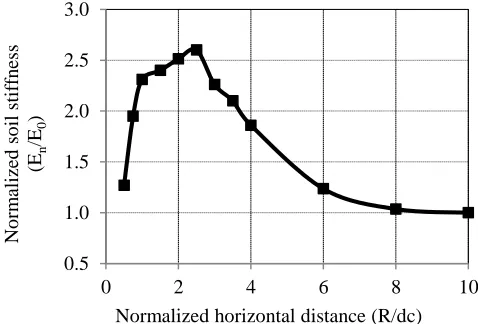
[image:7.612.52.287.408.573.2]stiffness after consolidation can be noticed in fig 9. This effect extends up to 6 times the column diameter and reaches a peak of 2.6 times the initial soil stiffness. It can be also noted in fig 9 that due to the applied dynamic vibration, a drop in the stiffness in the soil very close to column is expected as reason for a potential liquefaction in this area.
Fig. 8 Variation of stress within the clay with distance from the column axis (displacement degree = 0.2 m).
The last aforementioned two effects of the stone column installation are believed to have significant influence in the stone column foundation system performance. They have been neglected in many of the design methods nowadays. For the purpose of studying these influences, a programme of numerical analysis to quantify their impact, as a function of the expansion degree applied during stone column installation, has been carried out.
Fig. 9 Variation of stiffness of clay with distance from the column axis (displacement degree = 0.2 m).
0 0.05 0.1 0.15 0.2
0 2 4 6 8 10
L
ater
al
Dis
p
lace
m
en
t
(m
)
Normalized horizontal distance (R/dc)
0.0 2.0 4.0 6.0 8.0 10.0 12.0
0 1 2 3 4 5
U
/ U
0
Normalized horizontal distance (R/dc)
0.8 1.0 1.2 1.4 1.6 1.8
0 2 4 6 8 10
No
rm
alize
d
later
al
p
ress
u
re
co
ficien
t
(K
n
/K
0
)
Normalized horizontal distance (R/dc)
0.5 1.0 1.5 2.0 2.5 3.0
0 2 4 6 8 10
No
rm
alize
d
s
o
il st
if
fn
ess
(E
n
/E
0
)
[image:7.612.320.559.509.671.2]B.Effect of expansion degree on bearing capacity settlement performance
In aforementioned numerical programme, the improvement in bearing capacity and settlement performance of the soft soil around the stone column due to displacement installation of the column were evaluated. Eight different column expansion
degree cases ( d= 0.10, 0.15, 0.2, 0.25, 0.30, 0.35, 0.4 and
0.45 m) were simulated and numerically analysed. The results showed that increasing the expansion during column installation has a very important effect on improving the bearing capacity and reducing the settlement of reinforced ground.
Fig. 10 Effect of expansion degree of the installed stone column on bearing capacity of reinforced footing.
[image:8.612.53.292.204.372.2]Looking at fig 10, it is clear that the development of the bearing capacity performance can be increased up to 35% for the full displacement stone column compared with the full replacement one. This increase is a direct resultant of stiffness and K* development around the column due to the installation. Settlement criteria are usually govern the design of the foundation on soft soils rather than the bearing capacity So, more important results are illustrated in fig 11. The settlement improvement factor can be up to 55% increase at full displacement construction for the stone column.
Fig. 11 Effect of expansion degree of the installed stone column on settlement of reinforced footing.
V.CONCLUSIONS
A series of axisymmetric numerical analysis has been carried out to study the installation effect of a single stone column in natural well documented Bothkennar Clay by adopting unit cell concept. Two main effects were found;
Increase the coefficient of lateral earth pressure as a result of applying the cavity expansion during installation.
Significant increase the stiffness of the enhanced soft soil around the column after installation and consolidation.
Different degrees of stone column lateral expansions were studied, and then the changes in the stress state and settlement performance were quantified. The results demonstrate a significant improvement in the performance of this composite foundation when the applied lateral displacement of the installed column increases. Confirming the fact that; neglecting the role of the soft soil in stone column reinforcement system design will end with about 50% under estimation of the settlement performance for these foundations.
REFERENCES
[1] Allman, M. A. and Atkinson, J. H. (1992). Mechanical properties of reconstituted Bothkennar soil. Géotechnique, Vol. 42, No. 2, 289–301
[2] Ambily, A., Gandhi, S. (2007). Behaviour of Stone Columns Based on Experimental and FEM Analysis. Journal of Geotechnical and Governmental Engineering , ASCE, 133: 405-415.
[3] Brinkgreve, R. B. J and Broere, W. (2011). PLAXIS 3D Foundation Manual Version 2. PLAXIS BV
[4] Castro, J. (2007). Pore pressures during stone column installation. Proc. 18th European Young Geotechnical Engineers' Conference, Ancona
[5] Castro, J. and Sagaseta, C. (2009). Consolidation around stone columns. Influence of column deformation. Int. Journal for Numerical and Analytical Methods in Geomechanics, Vol. 33, Issue 7, 851–877
[6] Debats, J. M., Guetif, Z. and Bouassida, M. (2003). Soft soil improvement due to vibro-compacted columns installation. Proc. Int. Workshop on Geotechnics of Soft Soils - Theory and Practice, Noordwijkerhout, Netherlands, 551–556
[7] Elshazly, H. A., Hafez, D. and Mosaad, M. (2006). Back calculating vibro-installation stresses in stone columns reinforced ground. Proc. of the ICE - Ground Improvement, Vol. 26, Issue 2, 47– 53
[8] Elshazly, H., Elkasabgy, M. and Elleboudy, A. (2008b). Effect of inter-column spacing on soil stresses due to vibro-installed stone columns: Interesting findings. Journal of Geotechnical and Geological Engineering, Vol. 26, No. 2, 225–236
[9] Gäb, M., Schweiger, H. F., Thurner, R. and Adam, D. (2007). Field trial to investigate the performance of 0.8
1.0 1.2 1.4
0 0.1 0.2 0.3 0.4 0.5
B
ea
rin
g
P
ress
u
re
im
p
ro
v
em
en
t
fac
to
r
(m
)
Normalized expansion Degree ( d/dc)
1.00 1.10 1.20 1.30 1.40 1.50 1.60
0 0.1 0.2 0.3 0.4 0.5
Settlem
en
t
Im
p
ro
v
em
en
t
Facto
r
(n
)
[image:8.612.53.293.550.706.2]floating stone columns. Proc. 14th European Conf. on Soil Mechanics and Geotechnical Engineering, Madrid, 1311–1316
[10]Gäb, M., Schweiger, H. F., Kamrat-Pietraszewska, D. and Karstunen, M. (2008). Numerical analysis of a floating stone column foundation using different constitutive models. Proc. 2nd Int. Workshop on Geotechnics of Soft Soils, Glasgow, 137–142 References 226
[11]Gill, D.R. and Lehane, B.M. (2001). An optical technique for investigating soil displacement patterns. Geotechnical Testing Journal, Vol. 24, 324–329
[12]Guetif, Z,. Bouassida, M,. Debats, JM. (2007). Improved soft clay characteristics due to stone column installation. Comput Geotech 34: 104-111.
[13]Han, J. and Ye, S. L. (2001). Simplified method for consolidation rate of stone column reinforced
foundations. Journal of Geotechnical and
Geoenvironmental Engineering, ASCE, Vol. 127, No. 7, 597–603
[14]Hight, D. W., Bond, A. J., and Legge, J. D. (1992). Characterization of the Bothkennar clay: an overview. Géotechnique, Vol. 42, No. 2, 303–347
[15]Jardine, R. J., Lehane, B. M., Smith, P. R. and Gildea, P. A. (1995). Vertical loading experiments on rigid pad foundations at Bothkennar. Géotechnique, Vol. 45, No. 4, 573–597
[16]Keller Foundations Group – Stone Column Installation <http://kellerfoundations.co.uk/technique/vibro-stone-columns> (Accessed 25 June 2011).
[17]Killeen, M.M., 2012, Numerical modelling of small groups of stone columns (Ph.D. thesis). National University of Ireland, Galway.
[18]Kirsch, F. (2004) vibro stone column installation and its effect on ground improvement. Vortrage der Bavgrundtagung, Leipzin. 149-156 Essen VGE.
[19]Kirsch, F. (2006). Vibro stone column installation and its effect on the ground improvement. Int. Conf. on Numerical Simulation of Construction Processes in Geotechnical Engineering for Urban Environment, Bochum, 115–124
[20]Kirsch, F. (2008). Evaluation of ground improvement by groups of vibro stone columns using field measurements and numerical analysis. Proc. of the 2nd Int. Workshop on the Geotechnics of Soft Soils, Glasgow, 241–248
[21]Leroueil, S., Lerat, P., Hight, D. W. and Powell, J. J. M. (1992). Hydraulic conductivity of a recent estuarine silty clay at Bothkennar. Géotechnique, Vol. 42, No. 2, 275– 288
[22]Mitchell, J.K. and Huber, T. R. (1985). Performance of a stone column foundation. Journal Geotechnical Engineering, ASCE, Vol. 11, No. 2, 205–223
[23]Munfakh, G. A., Sarkar, S. K. and Castelli, R. J. (1984). Performance of a test embankment founded on stone columns. Proc. Int. Conf. on Advances in Piling and Ground Testing, London, 259–265
[24]Nash, D. F. T., Sills, G. C. and Davison, L. R. (1992b). One-dimensional consolidation testing of the soft clay from Bothkennar. Géotechnique, Vol. 42, No. 2, 241–256
![Fig. 1 Vibro displacement by dry bottom-feeding method, [16].](https://thumb-us.123doks.com/thumbv2/123dok_us/7805511.171116/2.612.315.567.352.483/fig-vibro-displacement-dry-feeding-method.webp)
![Fig. 2 Axisymmetric problem, [25].](https://thumb-us.123doks.com/thumbv2/123dok_us/7805511.171116/3.612.346.526.537.676/fig-axisymmetric-problem.webp)
![Fig 4 Comparison of Plaxis 2D AE modeling results with real load- displacement behaviour for a field footing done by [15]](https://thumb-us.123doks.com/thumbv2/123dok_us/7805511.171116/6.612.50.286.493.610/comparison-plaxis-modeling-results-displacement-behaviour-field-footing.webp)