i
IMPROVING THE ACCURACY OF OPEN SOURCE 3D SCANNING MACHINE
NADIA ILYSA BINTI RASIMAN
IMPROVING THE ACCURACY OF OPEN SOURCE 3D SCANNING MACHINE
NADIA ILYSA BINTI RASIMAN
A report submitted
in fulfillment of the requirements for the degree of Bachelor of Mechanical Engineering (Design and Innovation)
Faculty of Mechanical Engineering
UNIVERSITI TEKNIKAL MALAYSIA MELAKA
i DECLARATION
I declare that this project entitled “Improving the Accuracy of Open Source 3D Scanning Machine” is the result of my own work except as cited in the references.
Signature : ………
Name : NADIA ILYSA BINTI RASIMAN
ii APPROVAL
I hereby declare that I have read this project report and in my opinion this report is sufficient in terms of scope and quality for the award of the degree of Bachelor of Mechanical in Engineering (Design and Innovation).
Signature : ………..
Name of Supervisor : ……….
iii ABSTRACT
iv ABSTRAK
Didalam projek ini, Microsoft Kinect merupakan medium yang digunakan sebagai satu
peranti pengimbas 3D yang murah dengan mengunakan Kinect Xbox 360 sebagai alat pengukur
untuk mengimbas objek. Tujuan utama projek ini ialah untuk merekabentuk satu konsep baru
yang berkaitan kepada peranti pengimbas 3D yang murah dan mengkaji struktur konsep
tersebut mengunakan analisis unsur terhingga dan seterusnya menghasilkan satu lukisan
lengkap mengunakkan perisisan permodelan perpejal. Kaedah yang digunakan dalam projek
ini menjurus kepada kaedah lukisan kejuruteaan dimana proses ini bermula daripada
menyenaraikan semua idea yag berkaitan dengan projek. Seterusnya, konsep carta morfologi
telah diketengahkan untuk menghasilkan beberapa konsep baru dan melalui beberapa konsep
baru ini, satu analisis yang dipanggil carta pugh telah dibuat untuk menganalisis konsep yang
paling sesuai untuk digunakan dalam projek ini. Setelah itu, konsep baru ini akan digunakan
untuk meletakkan Kinect Xbox 360 ini untuk mengimbas bebrapa objek yang statik pada 360
darjah pusingan. Skanect merupakan medium yang digunakan untuk memproses objek ini
didalam bentuk maya dalam 3 dimensi.Skanect merupakan satu perisian yang bersifat terbuka
dimana perisian ini akan digunakan untuk mengubah fungsi Microsoft Kinect kepada peranti
pengimbas 3D yang murah untuk mengimbas keseluruhan data objek termasuk warna asal
objek tersebut. Daripada hasil kajian, kasut sukan mempunyai nilai perbezaan yang tinggi
antara ukuran asal dan ukuran daripada peranti pengimbas iaitu 8.6% ikuti oleh kerusi dengan
nilai 6.25% dan nilai yang terendah merupakan kotak dengan nilai dapatan sebanyak 1.6%.
Secara konklusinya, dengan mengunakkan konsep mengerakkan peranti pengimbas dengan
mengerakkan secara 360 darjah mengelilingi objek dapat mengurangkan kadar perbezaan
v
ACKNOWLEDGEMENT
In the name of Allah, the most Gracious and most Merciful, I am grateful as I am managed to finish my final year project which is known as Projek Sarjana Muda II (PSM II) for this semester. I am grateful and would like to express my gratitude my supervisor Dr Faiz Redza bin Ramli for all his advices and supports. All the advices and supports were really helping me a lot in order to complete my project. Not forget to mention, I would like to thank to all lectures and technician who has taught and guided me during my period of studying in engineering field.
vi
TABLE OF CONTENTS
DECLARATION i
APPROVAL ii
ABSTRACT iii
ABSTRAK iv
TABLE OF FIGURE viii
LIST OF TABLE x
INTRODUCTION 1
1.1 BACKGROUND 1
1.2 PROBLEM STATEMENT 2
1.3 OBJECTIVE 3
1.4 SCOPE OF PROJECT 3
1.5 GENERAL METHODOLOGY 4
2.1 INTRODUCTION 5
2.2 REVERSE ENGINEERING 6
2.3 3D SCANNING SYSTEM 8
2.4 MICROSOFT KINECT 12
2.5 POINT CLOUD 15
2.6 IMAGE PROCESSING 18
METHODOLOGY 19
vii
3.2 PROCESS FLOW CHART 20
3.3 CONCEPTUAL DESIGN 22
3.4 MORPHOLOGICAL CHART 23
3.5 DETAIL DESIGN 27
3.6 MANUFACTURING PROCESS 29
RESULT AND DISCUSSION 30
4.1 DESIGN PROTOTYPE 30
4.2 CENTRIFUGAL FORCE 31
4.3 BEARING DESIGN 32
4.4 EXPERIMENT SET UP 34
4.5 RESULT 35
4.6 DESIGN OF EXPERIMENT (DOE). 39
4.7 DISCUSSION 42
CONCLUSION 44
viii TABLE OF FIGURE
Figure 1.1 Flowchart of Methodology of 3D Scanning Process 4 Figure 2.1 Experiment Set-up of Scanning Process 6 Figure 2.2 Classification of 3D Measuring Optical Method 9 Figure 2.3 3D Reconstruct Face Data From Different View of Angle 11 Figure 2.4 Face Scanning Process by Using Multi-image Process 11
Figure 2.5 Resulting 3D Point Cloud 12
Figure 2.6 Microsoft Kinect for Xbox 360 13
Figure 2.7 Triangulation Process of Kinect Sensor 14 Figure 2.8 (a) Infrared image of speckles pattern 14
Figure 2.8 (b) Depth image result 14
Figure 2.9 Flowchart of Methodology of 3D Scanning Process 16 Figure 2.10 Meshes created by using Mesh3D triangulation algorithm 17 Figure 2.11 Flow Chart Process of Data Reduction Process 18 Figure 3.1 Process Flow chart for Development Product 22 Figure 3.2 Morphological Chart of the rotating platform 23
Figure 3.3 Design 1 of combining each component sub alternatives component 24 Figure 3.4 Design 2 of combining each component sub alternatives component 25 Figure 3.5 Design 3 of combining each component sub alternatives component 25
Figure 3.6 (a) Rotating Platform 27
Figure 3.6 (b) FEA of Rotating Platform 27
Figure 3.7 (a) Rotating Platform connected with bearing 28
Figure 3.7 (b) FEA analysis result 28
Figure 3.8 Kossel 3D Printer 29
ix
Figure 4.3 Bearing Schematic 33
Figure 4.4 Experimental Setup 34
Figure 4.5 (a) Real chair 35
Figure 4.5 (b) Virtual 3D scanned chair 35
Figure 4.5 (c) Real box 35
Figure 4.5 (d) Virtual 3D scanned box 35
Figure 4.6 (a) Real shoes box 36
Figure 4.6 (b) Virtual 3D scanned chair 36
Figure 4.6 (c) Real cup 37
Figure 4.6 (d) 3D cup in CAD file 37
Figure 4.7 Process to measure the dimension of 3D virtual shoes box 37 Figure 4.8 Graph of percentage difference of each data. 39 Figure 4.9 Main effect plot for response 40 Figure 4.10 Interaction plot
x LIST OF TABLE
Table 2.1 Descriptions of the Object’s Measurement 8 Table 3.1 Product design specification 22
Table 3.2 Pugh concept selection process 26 Table 4.1 List component of rotating platform with fixed center 31
Table 4.2 Formula 33 Table 4.3 Data of Object 38 Table 4.4 Percentage Error of Object (Horizontal Length in cm) 38 Table 4.5 Factorial design factor of two-interaction 40 Table 4.6 Indicator of factor 40
1 CHAPTER 1
INTRODUCTION
1.1 BACKGROUND
Three dimension scanners (3D scanner) is a device that analysis object or environmental data. The data will be interpreted to produce three dimensional models. The first 3D scanning technology was created in the 1960s whereby early scanners used cameras, projectors and lights (Ebrahim, 2014). Due limitations to scan the object accurately, this scanners were replaced by using white light, shadowing and lasers to captured an object’s surfaces after 1985. First application of this 3D scanning is used in capturing human for animation industry by using Head Scanner. However, during this time, even the 3D scanner were developing in high detail scanners, still the degree and accuracy were still hard to achieve.
2
This Kinect sensor consists of color VGA video camera, depth sensor and multi-array-microphone. It works by inferring body position in two-stage process. This process is by direct compute a depth map and by inferring body position. This data can be stored and generate the 3D model in digital form by manipulating using computer programs.
1.2 PROBLEM STATEMENT
3D scanning technologies nowadays are way too advanced. It comes with high resolutions colors and even exists in portable shapes. However, these high technologies come with high price. This will be the problems for a small company to develop products. They tend to spend a lot of money to buy this kind of technologies. Considering for educational purpose, it is a waste to spend too much money for an expensive 3D scanner machine since in educational purposes, this machine only used to exposed students to know how this machine works and its real applications. Seeing that fact, having a low cost 3D scanner is enough for an educational purpose.
Besides, software is needed to deliver raw scan data. This software is crucial for enabling user to process the data obtained from the 3d scanner. A good software will exposed the user to minimize the spent data processing which makes it more efficient. However, the present software is costly and difficult to use. Mostly the software is designed for engineering or surveyors. Thus, it is not user friendly for the non-engineering sectors. Hence, a remodeling new model to more users friendly needs to be considered.
3 1.3 OBJECTIVE
The objectives of this project are:
●To generate new design concept of a low cost active 3D scanner.
●To analyze the structure of the low cost 3D scanner using finite element analysis. ● To produce detail design of 3D scanner using solid modeling software.
1.4 SCOPE OF PROJECT
The scopes of this project are:
1. Microsoft Kinect will be used to capture and detect the object’s surface.
4
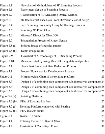
[image:16.612.213.406.122.434.2]1.5 GENERAL METHODOLOGY
Figure1. Flowchart of Methodology of 3D Scanning Process. Real Object
3D Scanner
Catia Aided Design (CAD) Point Cloud Data
5
LITERATURE REVIEW
2.1 INTRODUCTION
Nowadays, 3D scanners have become more popular and widely used tools. One of its widely field applications are in manufacturing industry, and in reverse engineering. In reverse engineering, these 3D scanners were used to create automotive parts. Basically these devices work to capture a two-dimensional object as an input and will produce a virtual three-dimension object as an output. The data captures were in points which known as point cloud. In detail, these devices will capture the depth of the object and produce a large number of points on the surface of the object. Later, the Standard Tessellation Language (STL) format will be produced by this point cloud whereby, this STL file only describes the surface geometry of the three-dimensional object without considering the colors and textures. Apparently, these devices were capable of representing virtual object with high good accuracy (Reyes et al, 2013). However, the price was extremely expensive making students or academic staffs less affordable to buy and use these devices either in academic or researcher purposed. Thus, a low cost 3D scanner will be proposed and design by using Microsoft Kinect as the 3D sensing device. In this design, some modification is made to make this Microsoft Kinect sensors act as an active 3D scanner. All the information is studied on how to improve the accuracy of this low-cost 3D scanner.
6 2.2 REVERSE ENGINEERING
Reverse engineering can be referred as consideration of the part objects on how it works in order to enhance or duplicate the objects. However, in 3D scanning, this reverse engineering refers to a process obtaining geometric shape from discrete sample. This discrete sample will be used to create mathematical models the CAD model does not exists. During this process, the product part is produce by extracting surfaces or sketches from the scanned object by using mesh or point cloud. Simply put, this reverse engineering in 3D scanning can produce three- dimensional model even without existing CAD files. The accuracy of the output can achieve up to 100 %. The output files can be transfer to any CAD and this output files can be function as inspection, tool path making, inspection or 3D printing and additive manufacturing.
Basically, the three-dimensional geometry for reverse engineering studies is focuses on distances or images (Herraez et al, 2016). S.M. Emam et al. (2014), have proposed a dithering technique (DT) to improve the accuracy of the laser scanning for three dimensional model reconstruction. This technique used an approach of distance through small movement of either the sensing array or the object and rescanning, and normally applied in signal and image processing application to reduce the amount of the error in the reference image. This DT method reduced the round off error by adding an external noise during the point cloud process. S.M.Emam et al. (2014), proposed this technique on the laser triangulation scanner by shifting the sensing array during capturing the scene. An experiment was carried out by using Sony XC-555P of 7681 (H) and 576(V) pixel with 8.33um pixel size. The output of depth reconstruction was studied by moving the camera sensor into two different positions. Results from the constructed depth were calculated to obtain the experimental depth value. Later, this value was compared with the actual value by using Coordinate Measuring Machine (CMM) with 0.001 mm accuracy. The results show that the accuracy of construction is improved by 50% relative a normal style acquisition.
7
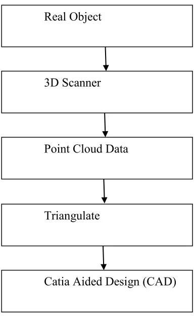
scanner is focuses on its development and implementation through a several testing and experiment. This study shows a relation between hardware of the milling machine (Mach3) and the scanning software of David-LaserScan using an active sensor which is CMOS sensor. Through this experiment, the 3D scanning system can make full 360° rotation scan of the objects. An algorithms code is produce by using Processing software which this algorithm will send a command to David and Mach3 software to control the movements of the CNC machine. From several experimental methods, the accuracy of measurement can be improved by increasing the triangulation base (B1 const) (Figure 2.1) or by using larger sensor.
[image:19.612.184.465.259.462.2]
Figure 2.1 Experiment Set-up of Scanning Process.
8
the measurement of distance between the selected triangle pair using triangulation process is acceptable.
2.3 3D SCANNING SYSTEM
9
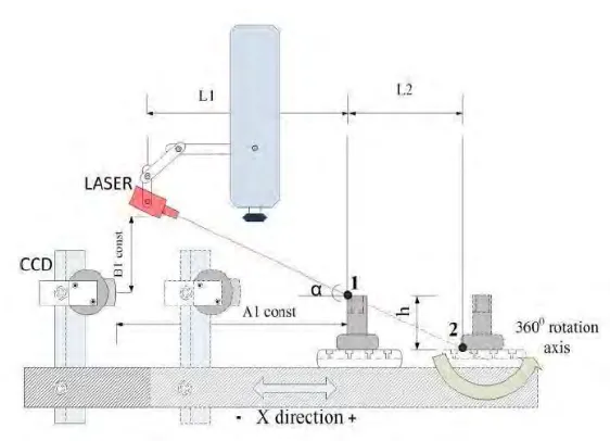
Figure 2.2 Classification of 3D Measuring Optical Method.
2.3.1 ACTIVE METHOD
Active 3D measurement method is a process which employs structure illuminations. This method is categorized as non-contact active optical 3D scanner. Bianco et al. (2013) have conducted an experiment to compare of 3D reconstruction data between active and passive method for underwater conditions. This comparison was conducted under the condition of poor visibility in a laboratory in turbid water by using structured light technique. As for active method, an active stereo technique was used by using hardware which is spatial, time, spectrum discrimination and polarization. From the result, the point cloud obtained from the active stereo technique gives more stables results in turbidity compared to passive stereo technique. In active 3D measurement method, it is require additional measurement to obtain the projected image data and controlled illumination process can be applied to overcome some overlapping image data. This illumination process is referred as structured light illumination (SLI) process. This SLI process is classified as non-contact active 3D triangulation based techniques whereby this process is has similar concept with stereo vision and is used to reduce the computational complexity of similar pixels across the camera view. This complexity is reduced by changing the positions of camera component with a projector that produces a series of
10
stripped patterns. The derivation data between the camera and projector pixel can be analyze by changing of the pattern at certain point. Basically, this 3D triangulation based technique is known for its low cost and high accuracy result.
2.3.2 PASSIVE METHOD
Passive method is also classified into non-contact optical 3D scanner. This non-contact offers a faster way in scanning object by collecting thousands of point cloud of an object at one time. In contrast with active method, this passive method is based on stereo vision which is more convenient and more applicable due to its less apparatus setup (Muquit, Shibahara, & Aoki, 2006). This passive measurement method only acquire one move or still camera to measure the image data. However, in this 3D measurement of using stereo vision, it is found that it is hard to find accurate corresponding image which makes it become poor to reconstruct the quality of projected image. Abdul et al. (2006) experiment on the 3D reconstruction by using passive 3D measurement method shows a successful result. During the 3D reconstruction, the projection matrices obtained from the camera and about 4000-5000 of corresponding points were used to reconstruct the real object. In this case, the reconstruction accuracy of a passive method system is observed and was compared to the light structured light projection. From the comparison with the structured light projection, the passive method data achieve 0.5mm accuracy in 3D measurement even with the narrow baseline stereo camera head.
11
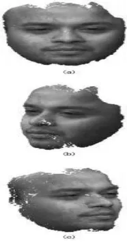
Figure 2.3 3D Reconstruct Face Data From Different View of Angle.
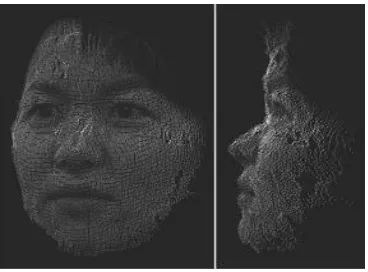
Multi-image photogrammetry is one of the passive methods which commonly used for human body measurement. This method utilizes multiple images acquired from multiple directions of the set up camera. The resulting point cloud of each different image is compute by the matching algorithms. In order to compute the 3D coordinates of human body measurement, a ray intersection is made to produce a dense 3D point cloud (Figure2.5). Figure 2.4 shows the result from the passive method of the intersection ray.
[image:23.612.233.442.462.640.2]
12
Figure 2.5 Resulting 3D Point Cloud.
2.4 MICROSOFT KINECT
Kinect is a line motion sensor devices introduced by Microsoft company. Initially, this invention is to use with video games for X-box, video game consoles and windows PC’s. The introduction of the Kinect camera has open a new impulse for 3D scanners whereby the first distribution of Kinect as 3D whole body scanners was in 2011 and the result shows the system works properly (Daanen & Ter Haar, 2013). In 3D scanning system, this device can be categories as a structural light scanner even though it uses a pattern of near infrared. In early introduction, this device using closed source system software compared to today which the open sources are now available (Daanen & Ter Haar, 2013).
[image:24.612.159.488.548.679.2]