Irrigation Control using Wireless Underground
Sensor Networks
Vinod Parameswaran
Computational Engineering and Science Research Centre (CESRC)Department of Mathematics and Computing
University of Southern Queensland
Hong Zhou
Computational Engineering and Science Research Centre (CESRC)
Faculty of Engineering and Surveying
University of Southern Queensland
Zhongwei Zhang
Computational Engineering and Science Research Centre (CESRC)Department of Mathematics and Computing
University of Southern Queensland
Abstract—Wireless Underground Sensor Networks (WUSN) using Electro-Magnetic (EM) wave communication has to address the challenges posed by the underground environment. An alternative to EM wave communication for WUSN is Magnetic Induction (MI). This research aims to study the possibility of using MI communication for WUSN designed for irrigation control in horticulture. As a case study, a typical Pecan farm in Australia has been considered. The case study would focus on the application of accurate soil moisture reporting and regulation for the farm, under all climatic conditions. This application addresses the issue of water-shortage confronting irrigation in Australia.
Keywords- Wireless Undeground Sensor Networks (WUSN); Surface Sinks and Relays; Underground-to-Aboveground Communication (UG2AG); Aboveground-to-Underground Communication (AG2UG); Underground-to-Underground Communication (UG2UG); Soil Moisture; Magnetic Induction (MI); Horticulture
I. INTRODCUTION
Irrigation control is one of the major application areas of Wireless Sensor Networks (WSN) in agriculture [14]. One of the requirements of irrigation control is to monitor soil conditions such as water and mineral content. Previous research has used both aboveground Wireless Sensor Networks (WSN) with underground sensors [5], [6] and Wireless Underground Sensor Networks (WUSN) [7] for similar purpose. This research project is a study of the applicability of MI communication for WUSN, designed for irrigation management in horticulture. As part of this study, a sample application scenario of a typical Pecan farm in Australia has been considered. The application of WUSN studied is accurate monitoring and reliable reporting of soil moisture under all climatic conditions. This information is assumed to be of critical use in precisely regulating the watering of the farm. This study is highly topical also because of the current water-shortage confronting irrigation in Australia.
This paper is the first part of a series based on the work accomplished as part of this project. The project is currently in network planning and design study phase, and the key aspects of this phase have been described in this paper under three distinct sections. The deployment considerations for the case study have been outlined under Section 2. Section 3 details the
sensor network architecture considerations, and explains the resultant sensor network topology model. The section also covers design decisions influenced by the model and the issues for further study. Section 4 presents a simulation output based on the underground deployment strategy. Section 5 concludes this paper with an overview of the planned future work.
II. DEPLOYMENT CONSIDERATIONS
The deployment considerations for the case study have been outlined below:
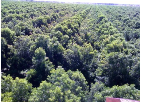
The WUSN is considered to be deployed in a large Pecan farm, similar to that shown in Figure 1. The farm area under consideration is around several hundred hectares, with a total tree population ranging in several tens of thousands. Assuming uniform planting, one tree is planted every k square units of distance. For the planning phase of the case study, a unit distance is represented by α. The tree distribution pattern has to be in accordance with the typical requirements of Pecan tree spacing for maximum yield, in addition to a minimum depth of 5 feet for optimum root penetration, and adequate but not excessive soil moisture [8]. Ensuring exact soil moisture is also significant in view of the water crisis confronting Australia in recent years.
The farm is subject to average to intense aboveground seasonal activity, including movement of harvesting machines transporting crops from the trees. This makes WUSN more suitable for sensing soil moisture conditions in the farm. The underground sensors would be relied upon to accurately sense and report soil moisture data for clusters of planted trees across different layers of the soil (light, medium and heavy), under all climatic conditions. We define a cluster as a group of closely planted trees. The soil moisture data for each cluster needs to be reported to a remote data and control center bordering the farm. This data would be used to correctly regulate the watering of the Pecan trees, so as to maximize the yield for each tree.
Apart from accuracy and reliability of data, cost-effectiveness and longevity of the network are also of utmost importance. Especially, the WUSN has to work without any mediation for at least five years under all climatic conditions, after deployment. Ideally, the WUSN should be self-sufficient, and
should be able to replenish itself before exhausting battery power. It should also be able to maneuver through the difficulties posed by the environment under different climatic conditions.
[image:2.595.55.285.124.290.2]There is no mobility expected of the nodes in the network.
Figure 1: Altitudinal view of the typical Pecan farm
III. SENSORNETWORKARCHITECTURE
A. Advantages of WUSN with MI
Wireless Underground Sensor Networks (WUSN) presents an edge over WSN with underground sensors in terms of
Concealment, Ease of deployment, Timeliness of data,
Reliability and Coverage Density [1]. Underground wireless communication through soil has been studied in [2]. This highly relevant study reveals that EM wave communication underground through soil is influenced by a host of factors such as burial depth of the sensors, the operating frequency, the modulation scheme and the Volumetric Water Content (VWC) of the soil. Magnetic Induction (MI) and seismic waves have been proposed as alternatives for WUSN communication [1]. MI has some inherent advantages for underground communication, such as uniform attenuation irrespective of medium, non-susceptibility to multi-path fading, simple and innate acknowledgement mechanism, and relatively simple transmission and reception techniques as opposed to complex antenna design in the case of EM waves [1] [3]. The transmission range of MI underground is also greater than that of EM waves [4].
B. Sensor Network Plan
The sensor network has been planned in terms of independent yet identical network units covering specific sections of the farm. The basic unit of classification is a cell, which covers the area of x adjacent trees (i.e., multiple clusters). The area covered by a cell is assumed to be multiple tens of squares of α. A sector is formed of z adjacent cells. The area covered by a sector is assumed to be multiple hundreds of squares of α. The entire farm area has been classified in terms of p sectors. The following calculations summarize the plan logic:
Area of a single tree (T) = mα2
Area of n number of trees/total farm area (A) = nmα2
Both of the above can be substituted with constants based on actual field values.
Area of x adjacent trees (cell) (C) = xmα2
Area of z adjacent cells (sector) (S) = zxmα2
It is assumed that the total number of sectors should cover the entire farm area, and hence should be equal to the entire farm area (A). Using the area of a single tree (T) and the entire farm area (A), a close approximation can be arrived at for the values of area of a cell (C) and area of a sector (S), by dividing the total farm area into identical units enclosed by the minimum number of trees, economized for optimum coverage.
Since much of the aboveground is subject to activity, the placement of the aboveground sink nodes has to be confined to specific regions of the farm. The area covered under a single aboveground sink node could exceed multiple thousands of squares of α, ranging across multiple sectors. For maximum coverage at minimum cost using this plan, an underground sensor node has to be deployed per sector. To optimally synchronize the underground and aboveground networks, an underground sink node would be considered for the number of sectors covered by an aboveground sink node. Underground-to-Aboveground (UG2AG) and Underground-to-Aboveground-to-Underground (AG2UG) bi-directional communication has to be accomplished using EM waves. For Underground-to-Underground (UG2UG) bi-directional communication, MI would be explored.
The whole network plan would be envisaged as a replication of the above unit plan. During the initial phase of the case study, all simulations, prototyping and deployments would be focused on the unit plan.
C. Underground to Aboveground Communication
Underground to Aboveground (UG2AG) and Aboveground to Underground (AG2UG) bi-directional communication has to be accomplished using EM waves. A prototype for UG2AG-AG2UG bi-directional communication has been presented in [9]. This prototype has been based on a Full-Wave antenna combined with Single Ended Elliptical Antenna (FW/SEA) scheme. The proposed FW/SEA scheme uses a commercial magnetic 433MHz, full wave (FW), 3dBi-gain antenna aboveground, and a customized ultra wideband single ended elliptical antenna (SEA) for 3.1−10.6 GHz [10] underground. Using this antenna scheme, it has been shown that the communication range could be increased by over 350% compared to the original antenna scheme of the 433MHz Mica2 motes. The experiments have been conducted at different burial depths and under different soil moisture conditions.
underground sink nodes. The burial depth of the underground sink nodes should be less than that of the underground sensor nodes. The horizontal distance between the underground and aboveground sink nodes would be determined by the placement of the aboveground sink nodes, taking the aboveground activity zones into consideration. In [9], a symmetric region has been identified for UG2AG-AG2UG bi-directional communication based on experiments with varying burial depth and horizontal distance between the aboveground and underground nodes. It has been pointed out that in this symmetric region, the difference between the PER of the UG2AG and AG2UG communication is not greater than 10%. This case study would focus on identifying a similar PER region for optimal burial depth and horizontal distance between the aboveground and underground sink nodes.
D. Underground to Underground Communication
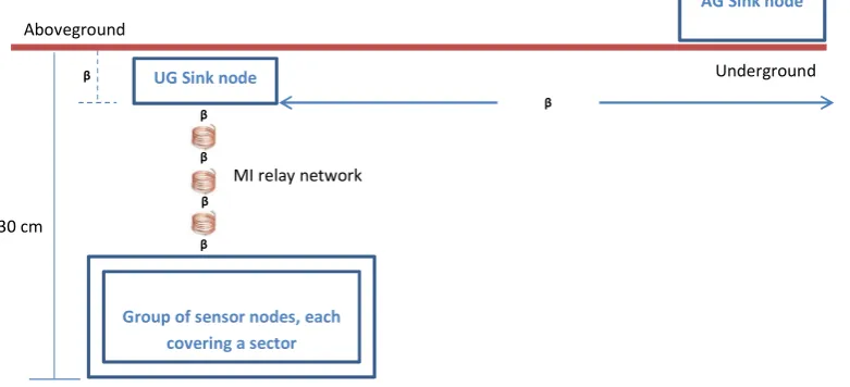
The roots of a mature Pecan tree may be more than 10 feet deep, but most of the feeder roots will be located in the upper 12 inches of the soil [8]. Hence each sensor node has to be deployed at a depth of 30 cm.
In terms of Underground to Underground (UG2UG) communication, a sensor node can be assumed to be at a minimum horizontal distance of kα from the sink node and a maximum distance of jα. Thus the UG2UG communication has to happen at a maximum horizontal distance of jα and depth of 0.3 m through soil conditions dependent on the season. The farm is characterized by black soil rich in clay content. Previous study [2] has shown that for such soil types, the average maximum internode distance for high quality communication (a target BER of 10-3) at a depth of 0.3 m is 2 m, for transmission in the 300-900 MHz band suitable for motes. This range is assumed to be way below the actual distance between an underground sensor node and the underground sink node.
The reported transmission range of MI underground is around 10 m [4], which also should fall much short of the maximum possible distance between an underground sensor node and the underground sink node.
E. MI Waveguide System Model
A MI waveguide system model for underground communication has been presented in [4], wherein the transmitter and the receiver have been modeled as the primary and secondary coils of a transformer, and equidistant relay coils have been placed between the transmitter and the receiver to increase the transmission range, where each relay coil has been loaded with a capacitor. According to this study, the relay coils offer both cost advantage as well as energy savings over the relay points used in EM wave transmission, in addition to achieving greater relay distance. The model has been subject to the following assumptions:
1. The soil should be free of the presence of magnetite. 2. The soil permeability has been considered to be the same
as that of air, which is 4πx10-7H/m. This is due to the reason that path loss in MI communication is not affected by the medium.
3. The average noise level of the soil should be -103 dBm to achieve the target BER of 10-3.
4. In order to maximize the received power, the capacitor value for each coil should be so defined that the coil is resonant and the impedance of the coil is only determined by its resistance. This has been captured in the following equation:
Z = R + jωL + 1/jωC (1)
Where Z is the load impedance of the coil; R is the coil resistance; L is the coil self-inductance; C is the capacitor loaded in the coil; and ω is the angle frequency of the transmitting signal, ω = 2πf where f denotes the system operating frequency.
In order for the impedance of the coil to be determined by its resistance alone, jωL + 1/jωC should be 0 in (1). Based on this condition, the capacitor for each coil has been defined using the following equation:
C = 2/ω2N2μπa (2)
Where N is the number of turns of the coil; a is the radius of the coil; and μ is the permeability of the soil.
5. The relay coils are assumed to be uniformly distributed between the transceivers, and placed at accurate positions with respect to one another. The mutual induction between two coils is assumed to be uniform throughout the distribution, so that the entire transmission range can be specified in terms of equal relay intervals.
In addition, the following parameters have been considered for the model:
1. The radius of each coil has been set to 0.15 m. 2. The number of turns for each coil has been set to 5. 3. The material of each coil has been set to copper wire and
the corresponding diameter to 1.45 mm. The resultant wire resistance as per the American Wire Gauge (AWG) [11] specifications measures as 0.01 Ω/m.
4. The operating frequency has been set to 10 MHz. 5. The transmission power has been set to 10 dBm. 6. The modulation scheme has been set to 2PSK.
7. The distance between two relay coils has been set to 5 m. Using the above parameters with the assumptions, a communication range of 250 m at a bandwidth of 1 KHz and a BER of 10-3 has been predicted by the model. Using the same settings but reducing the distance between the coils to 4 m, a higher bandwidth of 2 KHz and a greater communication range of 400 m have been projected.
F. Model vs Plan
1. Assumption 5 in the model needs to be evaluated depending on the actual deployment conditions underground. As per the model, standard deviation of path loss and bandwidth consumed increases with deployment deviation, and any deviation from ideal deployment by a factor greater than 10% could dramatically increase the standard deviation of path loss and bandwidth.
2. Parameter 7 of the model can be a constraint considering the relatively large required relay distance.
3. Parameter 4 and Parameter 5 considered for the model might not suit the actual deployment conditions.
In view of the above and other probable unidentified differences, the case study would consider the basic model proposed in [4] for achieving 1 KHz bandwidth at 250 m transmission range, as the baseline MI waveguide system design. Modifications necessitated by the deployment environment would be implemented on top of this design.
[image:4.595.123.514.474.652.2]G. Sensor Network topology model
Figure 2 shows the topology model considered for the unit plan. As mentioned under section III B, the unit plan is based on the total coverage area for a single aboveground sink node. The following are the variables that need to be determined based on the deployment conditions:
1. The maximum feasible horizontal distance between the aboveground sink node and the underground sink node has to be determined.
2. The maximum feasible horizontal distance between the underground sink node and an underground sensor node across multiple sectors has to be determined.
3. The maximum feasible relay distance has to be determined.
4. The burial depth of the underground sink nodes has to be determined.
Figure 2: Sensor network topology model for unit plan
In the figure, all of the above variables have been denoted using β.
H. Cost Advantage
The hardware for the underground senor nodes should be very simple and highly cost-effective, in the absence of complex antenna design. Each sensor node would be equipped with a MI transmitter, implemented using a small ferromagnetic coil or an embedded RFID-type coil as an antenna [3]. These nodes could also function as MI receivers to extract data from an induced voltage [3], and as additional relays. The underground sink nodes would also be MI transmission and reception capable, so as to enable bi-directional communication. The relay coils are also simple in design, and highly cost-effective and energy-efficient as explained in [4].
Further cost-advantage would depend on maximizing the coverage area for a single underground sink node, sensor node and relay node. This has to be achieved by a combination of hardware improvements to meet field conditions, and optimization of the unit plan. A primary concern is not to trade reliability and efficiency for cost-advantage.
I. Power Conservation
The issue of power conservation for the underground nodes is currently under study. The aim is to use a power-scavenging mechanism as the constant source of power to the nodes, so as to eliminate the need for a battery. Of the different options for power-scavenging [12], the most congenial option seems to be piezoelectric conversion since electro-magnetic conversion can generate only 180 mv as shown by previous research output [13]. Besides, it should be possible to design relatively miniscule systems of the order of 1cm3 for generating an output of 3-10 V using piezoelectric conversion, in the vicinity of a particular vibration threshold [12]. Since the burial depth under consideration is less than 1 m and because of the constant aboveground activity, it is assumed that the corresponding
Group of sensor nodes,
Group of sensor nodes, each covering a sector
30 cm
Underground Aboveground
MI relay network
UG Sink node
β
AG Sink node
β
β β
β
ambient vibration should be above this threshold. Additionally, piezoelectric methods to generate power from underground noise would be investigated.
Another key factor in power conservation is the effective synchronization of the sleep/wake-up cycle of the underground sensor nodes monitored by a sink node. Depending on the sensing interval, the sensor nodes could lay dormant after a reading and wake-up just in time to transmit the reading to the sink node.
J. Other Design Aspects and Issues
Identification of each node is supposed to be based on its relative position within the unit plan, which should guarantee uniqueness. Further study is required about the underground MAC protocol, but one preliminary consideration is to use a simple polling mechanism, also because it should facilitate synchronization of the sleep/wake-up cycle of the underground sensor nodes reporting to a sink node. This requires further feasibility study keeping in view the number of underground sensor nodes to be polled. Study also needs to be conducted about the data aggregation mechanism at the underground sink node. It could be either collation by means of a simple array-like data structure or consolidation into a single value if this is found unwieldy, in keeping with the number of data instances. The software architecture should also address the polling interval and a general synchronization mechanism underground, both during initialization and operation. The MAC control between the aboveground and underground sink nodes should be a simple bi-directional communication between the two sink nodes. The requirement of sensing and reporting moisture across different layers of the soil would also be taken up at a later stage of the case study. The focus has been placed for the initial phase of the study on the soil region between 10 and 40 cm depth, where most of the moisture activity is typically observed in the case of Pecan trees.
IV. PRELIMINARY SIMULATIONS AND RESULTS Preliminary simulations were done to study the impact of the recommendations in [15] on the deployment strategy. The deployment conditions of this case-study resemble the random topology identified in [15], since the underground sensors need to monitor only specific positions and the suitability of parts of the underground for deployment needs to be determined. The end-objectives of the deployment strategy would be to optimize the reliable coverage for a particular transmission power at minimal cost. Consequently, the number of relay coils and the algorithm used for their relative deployment are significant.
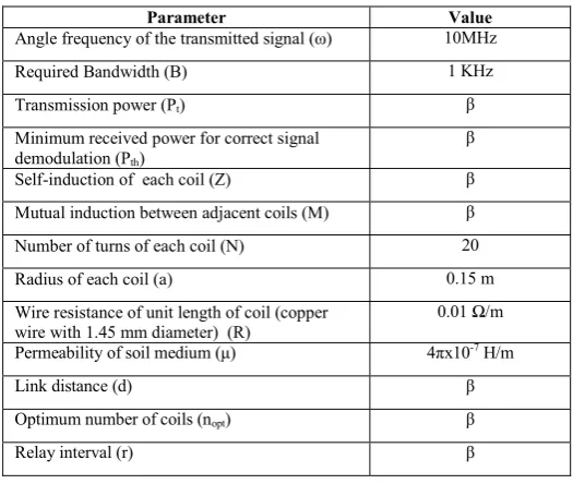
For a simulation based closely on ground conditions, the corresponding parameter values in [4] and [15] have been taken into consideration. In Table 1, the relevant parameters for the simulation have been presented. The parameters which would take on variable values in the simulation have been indicated using β. Of the variables, the three main parameters are the Link distance (d), the Transmission power (Pt) and the Minimum power of the received signal (Pth). The remaining variables take on values determined by the values of the three main variables. The values for the rest of the parameters have
been listed as constant values. The assumption in [4] has been adopted for the simulation, which is that all the coils have the same parameters (resistance, self and mutual induction). In Table 2, the relevant equations [4] [15] used in the simulation have been listed.
TABLE 1:PARAMETERS FOR BASLINE DEPLOYMENT OPTION
Parameter Value
Angle frequency of the transmitted signal (ω) 10MHz
Required Bandwidth (B) 1 KHz
Transmission power (Pt) β
Minimum received power for correct signal demodulation (Pth)
β
Self-induction of each coil (Z) β
Mutual induction between adjacent coils (M) β
Number of turns of each coil (N) 20
Radius of each coil (a) 0.15 m
Wire resistance of unit length of coil (copper wire with 1.45 mm diameter) (R)
0.01 Ω/m
Permeability of soil medium (μ) 4πx10-7H/m
Link distance (d) β
Optimum number of coils (nopt) β
Relay interval (r) β
TABLE 2:EQUATIONS USED IN SIMULATION [4][15]
Equation Description
LMI(d, n, ω) = 6.02 + 20 lgζ(R/ωM, n)
R/ωM = 4R/ωNμπ . (r/a)3
The path loss of the MI waveguide system (LMI) as a monotonically increasing function of R/ωM. Note that R = Z, when ω = ω0.
M ≈μπN2a4/4(d/n)3 Approximation for the mutual induction between adjacent coils.
nopt(d,B) = argminn{Pt – LMI(d, n, ω0 + 0.5B) ≥ Pth}
Optimum number of relay coils for covering a link distance d, to ensure a minimum received power. In the equation, the transmission signal frequency ω is assumed to deviate from the central signal frequency ω0 by 50% of the required bandwidth B.
Based on ground deployment conditions, a range of values was assigned to the three main variables d, Pt and Pth as part of the simulation. These values have been listed in Table 3.
TABLE 3:RANGE OF PARAMETER VALUES FOR SIMULATION
Parameter Range
Link distance (d) 100 – 125 meters
Transmission Power (Pt) 9 – 10 dBm
Minimum power of the received signal (Pth)
[image:5.595.300.563.135.357.2] [image:5.595.300.562.617.680.2]A standard configuration was also considered for the simulation, wherein fixed values were assigned to Pt and Pth and only the value of d was varied. The value of Pt was fixed as 10 dBm and that of Pth as -80 dBm.
[image:6.595.38.286.151.335.2]Figure 3 shows the values for the optimum number of coils (nopt) for the standard configuration, with varied values for d as listed in Table 3.
Figure 3: Simulation results for standard configuration
It can be seen from figure 3 that a minimum number of 33-43 relay coils is required to optimally cover the link distance ranging from 100-125 meters, at a Pt value of 10 dBm and a Pth value of -80 dBm.
[image:6.595.306.525.228.350.2]Figure 4 shows the simulation results with varied values for d and Pt as listed in Table 3. The value of Pth was fixed at the value of -80dBm for this simulation.
Figure 4: Simulation results with variable Pt
As seen in figure 4, the required number of minimum coils is more or less within the same range as in the case of the standard configuration shown in figure 3. This is explicable as the range of values considered for Pt in the case of figure 4 is not drastically different from the fixed value of 10 dBm considered in figure 3.
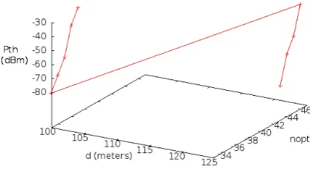
Figure 5 shows the simulation results with varied values for d and Pth as listed in Table 3. In this case, the value of Pt was fixed at 10 dBm.
Figure 5: Simulation results with variable Pth
The results in the case of figure 5 show a marked increase in the number of coils, as the range now has changed to 33-46 coils. When a large deployment area as in the case of the farm is considered, this could mean a substantial increase in the deployment cost. The results clearly indicate a steady increase in the minimum required number of coils with increasing received power. This is significant in view of the underground deployment conditions, where the random topology could necessitate a higher reception power for correct decoding of the signal at specific locations.
[image:6.595.37.260.536.651.2]V. CONCLUSION AND FUTURE WORK
Magnetic Induction (MI) presents a viable alternative to Electro-Magnetic (EM) wave communication for Wireless Underground Sensor Networks (WUSN). This paper outlined the specifics of the network planning and design study phase of a case study. The study forms part of a research to explore MI communication for WUSN, designed for irrigation control in horticulture. The application of WUSN considered for the case study is monitoring, reporting and eventually regulating soil moisture conditions for a typical Pecan farm.
This case study is expected to provide valuable insights into the use of MI communication for WUSN in general, and irrigation control in horticulture in particular. As part of the preliminary study, a series of simulations were conducted to arrive at a rough estimate of the optimal number of relay coils required for covering the entire farm area under consideration. Future work would extend this study by means of further detailed simulation and prototyping of the sensor network unit plan and its components, before actual deployment and field experiments. The initial deployment and tests would be approached as a proof-of-concept, with minimal cost to the industry. The end-objective would be to build a commercial version of the solution which would integrate the sensor network with a mechanism to regulate adequate water flow to the trees, so as to ensure maximum yield and water conservation.
VI. REFERENCES
[1] Ian F. Akyildiz, Erich P. Stuntebeck, Wireless underground sensor networks: Research challenges, Ad Hoc Networks, Volume 4, Issue 6, November 2006, Pages 669-686, ISSN 1570-8705, 10.1016/j.adhoc.2006.04.003.
[2] Mehmet C. Vuran, Ian F. Akyildiz, Channel model and analysis for wireless underground sensor networks in soil medium, Physical Communication, Volume 3, Issue 4, December 2010, Pages 245-254, ISSN 1874-4907, 10.1016/j.phycom.2010.07.001.
[3] Jack, Nathan; Shenai, Krishna; , "Magnetic Induction IC for Wireless Communication in RF-Impenetrable Media," Microelectronics and Electron Devices, 2007. WMED 2007.
[4] Zhi Sun; Akyildiz, I.F.; , "Magnetic Induction Communications for Wireless Underground Sensor Networks," Antennas and Propagation, IEEE Transactions on , vol.58, no.7, pp.2426-2435, July 2010.
[5] John McCulloch, Paul McCarthy, Siddeswara Mayura Guru, Wei Peng, Daniel Hugo, and Andrew Terhorst. 2008. Wireless sensor network deployment for water use efficiency in irrigation. In Proceedings of the workshop on Real-world wireless sensor networks (REALWSN '08). ACM, New York, NY, USA, 46-50.
[6] Martinelli, M.; Ioriatti, L.; Viani, F.; Benedetti, M.; Massa, A.; , "A WSN-based solution for precision farm purposes," Geoscience and Remote Sensing Symposium,2009 IEEE International,IGARSS 2009 , vol.5, no., pp.V-469-V-472, 12-17 July 2009.
[7] Agnelo R. Silva and Mehmet C. Vuran. 2010. (CPS)^2: integration of center pivot systems with wireless underground sensor networks for autonomous precision agriculture. In Proceedings of the 1st ACM/IEEE International Conference on Cyber-Physical Systems (ICCPS '10). [8] P.C. Andersen and T. E. Crocker, 2009, The Pecan Tree, HS982, Florida
Cooperative Extension Service, Institute of Food and Agricultural Sciences, University of Florida.
[9] Silva, A.R.; Vuran, M.C.; , "Communication with Aboveground Devices in Wireless Underground Sensor Networks: An Empirical Study," Communications (ICC), 2010 IEEE International Conference on , vol., no., pp.1-6, 23-27 May 2010.
[10] Powell, J.; Chandrakasan, A.; , "Differential and single ended elliptical antennas for 3.1-10.6 GHz ultra wideband communication," Antennas and Propagation Society International Symposium, 2004. IEEE , vol.3, no., pp. 2935- 2938 Vol.3, 20-25 June 2004.
[11] Standard Specification for Standard Nominal Diameters and Cross-Sectional Areas of AWG Sizes of Solid Round Wires Used as Electrical Conductors, ASTM Standard B 258-02, ASTM International, 2002. [12] Shad Roundy, Paul K. Wright, Jan Rabaey, A study of low level
vibrations as a power source for wireless sensor nodes, Computer Communications, Volume 26, Issue 11, 1 July 2003, Pages 1131-1144. [13] Amirtharajah, R.; Chandrakasan, A.P.; , "Self-powered signal processing
using vibration-based power generation," Solid-State Circuits, IEEE Journal of , vol.33, no.5, pp.687-695, May 1998.
[14] H. Karl, A. Willig, Protocols and Architectures for Wireless Sensor Networks, John-Wiley, New York, 2005.